Download as PDF, PPTX
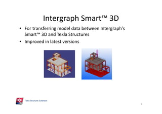
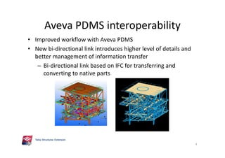
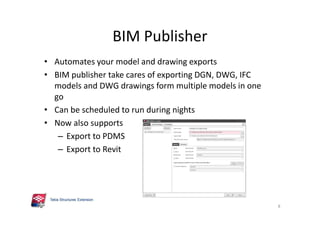
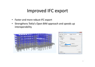
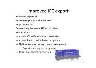
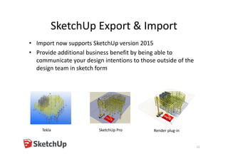


The document outlines the enhancements in Tekla Structures 21.0, focusing on interoperability and improved change management for IFC models. Key updates include automated exports through BIM Publisher, better IFC export capabilities, and enhanced workflow tools for integrating design teams. Additionally, new features for steel modeling, reinforced concrete, and improved drawing functionalities streamline the design process and facilitate collaboration with other software like Revit and Aveva PDMS.


![[제안서]Malaysia proton proposal](https://cdn.slidesharecdn.com/ss_thumbnails/malaysiaprotonproposal-100527111554-phpapp01-thumbnail.jpg?width=640&height=640&fit=bounds)


