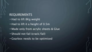
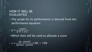
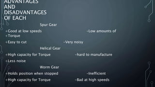
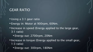
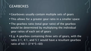
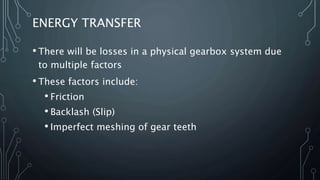
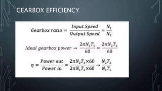
CREATIVE JOURNEY
PAUL RYAN, JONATHAN CHOW AND YALAINDRA SHUGUMAR
REQUIREMENTS
-Had to lift 8Kg weight
-Had to lift it a height of 0.5m
-Made only from acrylic sheets & Glue
-Should not fail (crack/fail)
-Gearbox needs to be optimised
HOW IT WILL BE
EVALUATED
-The grade for its performance is derived from the
performance equation
- 𝑝 =
(𝑚𝑔ℎ)2
( 𝑡2ܸ ‫ܫ‬ 𝐷3)
-Which then will be used to allocate a score
- 𝑠 =
(‫)݊݅݉݌−݌‬
(‫)݊݅݉݌−ݔܽ݉݌‬
10% + 10%
OUR APPROACH
-We first looked at the performance equation
-found which were constants
-determined the motors influence on the equation
-this led to whether we want it to be reliant on
efficiency or power
-This brought the variables t & D to discussion
-We will apply a factor of safety
-Over engineer by 20%
WHAT TYPE OF
GEAR IS MOST
SUITABLE
- Through calculations of the performance
we looked at the difference between
variables
-We then compared these to discover the
types of gears we wanted to use
-Originally we wanted helical
ADVANTAGES
AND
DISADVANTAGES
OF EACH
Spur Gear
+Good at low speeds -Low amounts of
+Torque
+Easy to cut -Very noisy
Helical Gear
+High capacity for Torque -hard to manufacture
+Less noise
Worm Gear
+Holds position when stopped -Inefficient
+High capacity for Torque -Bad at high speeds
GEARS
• Gears are used to increase speed, or to increase
torque
• Conservation of Energy law states that the total energy
in a closed system remains constant; energy cannot be
created or destroyed.
• Therefore any increase in speed would have to be
accompanied by a decrease in torque, and any
increase in torque, would result in a decrease in
speed.
GEARS
• In order to increase speed
• Energy applied to a large gear, which is connected
to a smaller gear
• In order to increase torque
• Energy applied to a small gear, which is connected
to a larger gear
GEAR RATIO
• A Gear Ratio is the ratio of the number of teeth between
two gears.
E.g. a 48 tooth spur gear to a 16 tooth pinion would have
a gear ratio of 48:16, which factors down to 3:1.
• For every revolution of the 48T spur gear, the 16T pinion
gear rotates three times.
• Using the gear ratio of a set of gears, we can calculate the
output speed/torque from the input speed/torque.
GEAR RATIO
• Using a 3:1 gear ratio
• Energy in: Motor at 900rpm, 60Nm.
• Increase in speed (Energy applied to the large gear,
3:1 ratio)
• Energy out: 2700rpm, 20Nm
• Increase in torque (Energy applied to the small gear,
1:3 ratio)
• Energy out: 300rpm, 180Nm
GEARBOXES
• Gearboxes usually contain multiple sets of gears
• This allows for a greater gear ratio in a smaller space
• The gearbox ratio (total gear ratio) of the gearbox
would be determined by multiplying the individual
gear ratios of each set of gears
• E.g. A gearbox containing three sets of gears, with the
ratio 3:1, 4:1, and 5:1 would have a resultant gearbox
ratio of 60:1 (3*4*5=60)
ENERGY TRANSFER
• There will be losses in a physical gearbox system due
to multiple factors
• These factors include:
• Friction
• Backlash (Slip)
• Imperfect meshing of gear teeth
GEARBOX EFFICIENCY
OPTIMIZING THE GEARBOX
• In order to optimize the gearbox, we would need to
calculate the torque required to lift the weight
• Once that’s done, we would need to increase our goal
torque by 20% as a factor of safety. This is so that we
don’t overwork the motor.
• Then, we would calculate the required gearbox ratio,
and thus the number of teeth in each set of gears
GEAR ARRANGEMENT:
- Our gear arrangement will be a Compound configuration
with a step reduction in each set.
- The number of gears that will be in the configuration is
still being assessed.
- The gear configuration needs to be strong to withstand the
forces of the weight.
Housing for the gears (Gearbox):
The housing for the gearbox will have some space on either
side of the step compound gears which may leave room for
movement of the gears, to prevent this we are considering
creating bushings to prevent any significant movement of the
gears. The shape of the gearbox may look something similar to
the shape of a bike chain configuration or we may decide on
choosing just a regular rectangle shaped box to avoid stress
fractures near the edges or near the output shaft.
Creative Journey Gearbox

Creative Journey Gearbox

  • 1.
    CREATIVE JOURNEY PAUL RYAN,JONATHAN CHOW AND YALAINDRA SHUGUMAR
  • 2.
    REQUIREMENTS -Had to lift8Kg weight -Had to lift it a height of 0.5m -Made only from acrylic sheets & Glue -Should not fail (crack/fail) -Gearbox needs to be optimised
  • 3.
    HOW IT WILLBE EVALUATED -The grade for its performance is derived from the performance equation - 𝑝 = (𝑚𝑔ℎ)2 ( 𝑡2ܸ ‫ܫ‬ 𝐷3) -Which then will be used to allocate a score - 𝑠 = (‫)݊݅݉݌−݌‬ (‫)݊݅݉݌−ݔܽ݉݌‬ 10% + 10%
  • 4.
    OUR APPROACH -We firstlooked at the performance equation -found which were constants -determined the motors influence on the equation -this led to whether we want it to be reliant on efficiency or power -This brought the variables t & D to discussion -We will apply a factor of safety -Over engineer by 20%
  • 5.
    WHAT TYPE OF GEARIS MOST SUITABLE - Through calculations of the performance we looked at the difference between variables -We then compared these to discover the types of gears we wanted to use -Originally we wanted helical
  • 6.
    ADVANTAGES AND DISADVANTAGES OF EACH Spur Gear +Goodat low speeds -Low amounts of +Torque +Easy to cut -Very noisy Helical Gear +High capacity for Torque -hard to manufacture +Less noise Worm Gear +Holds position when stopped -Inefficient +High capacity for Torque -Bad at high speeds
  • 7.
    GEARS • Gears areused to increase speed, or to increase torque • Conservation of Energy law states that the total energy in a closed system remains constant; energy cannot be created or destroyed. • Therefore any increase in speed would have to be accompanied by a decrease in torque, and any increase in torque, would result in a decrease in speed.
  • 8.
    GEARS • In orderto increase speed • Energy applied to a large gear, which is connected to a smaller gear • In order to increase torque • Energy applied to a small gear, which is connected to a larger gear
  • 9.
    GEAR RATIO • AGear Ratio is the ratio of the number of teeth between two gears. E.g. a 48 tooth spur gear to a 16 tooth pinion would have a gear ratio of 48:16, which factors down to 3:1. • For every revolution of the 48T spur gear, the 16T pinion gear rotates three times. • Using the gear ratio of a set of gears, we can calculate the output speed/torque from the input speed/torque.
  • 10.
    GEAR RATIO • Usinga 3:1 gear ratio • Energy in: Motor at 900rpm, 60Nm. • Increase in speed (Energy applied to the large gear, 3:1 ratio) • Energy out: 2700rpm, 20Nm • Increase in torque (Energy applied to the small gear, 1:3 ratio) • Energy out: 300rpm, 180Nm
  • 11.
    GEARBOXES • Gearboxes usuallycontain multiple sets of gears • This allows for a greater gear ratio in a smaller space • The gearbox ratio (total gear ratio) of the gearbox would be determined by multiplying the individual gear ratios of each set of gears • E.g. A gearbox containing three sets of gears, with the ratio 3:1, 4:1, and 5:1 would have a resultant gearbox ratio of 60:1 (3*4*5=60)
  • 12.
    ENERGY TRANSFER • Therewill be losses in a physical gearbox system due to multiple factors • These factors include: • Friction • Backlash (Slip) • Imperfect meshing of gear teeth
  • 13.
  • 14.
    OPTIMIZING THE GEARBOX •In order to optimize the gearbox, we would need to calculate the torque required to lift the weight • Once that’s done, we would need to increase our goal torque by 20% as a factor of safety. This is so that we don’t overwork the motor. • Then, we would calculate the required gearbox ratio, and thus the number of teeth in each set of gears
  • 15.
    GEAR ARRANGEMENT: - Ourgear arrangement will be a Compound configuration with a step reduction in each set. - The number of gears that will be in the configuration is still being assessed. - The gear configuration needs to be strong to withstand the forces of the weight.
  • 16.
    Housing for thegears (Gearbox): The housing for the gearbox will have some space on either side of the step compound gears which may leave room for movement of the gears, to prevent this we are considering creating bushings to prevent any significant movement of the gears. The shape of the gearbox may look something similar to the shape of a bike chain configuration or we may decide on choosing just a regular rectangle shaped box to avoid stress fractures near the edges or near the output shaft.