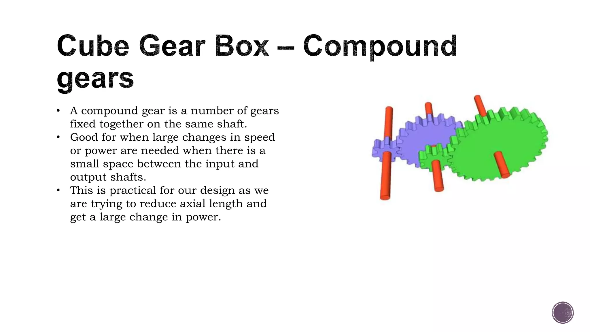
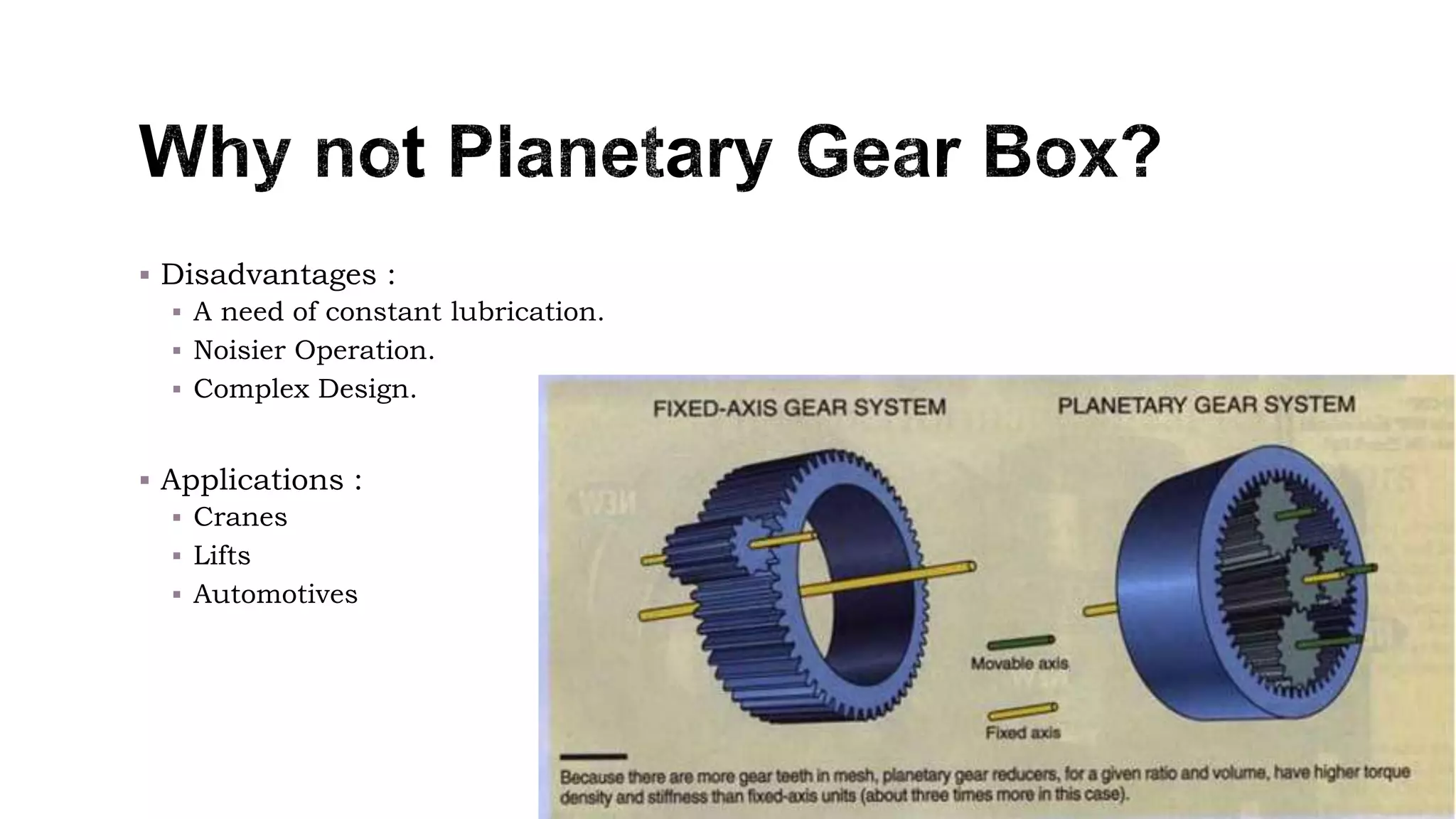
Gear Box Project
• Carl Wilson (Leader)
• Harry Oblak
• Georgia Albert
• Jason Teo
Planetary gears consist of three elements:
 Sun gear (gear in the middle)
 Planet gear (gears around the sun gear)
 The ring gear(gear on the outside).
 Each of these gears can be set as the input,
output or held stationary deciding which one is
determines the gear ratio.
 A benefit of a planetary gear box set up is it has
high efficiency.
• A compound gear is a number of gears
fixed together on the same shaft.
• Good for when large changes in speed
or power are needed when there is a
small space between the input and
output shafts.
• This is practical for our design as we
are trying to reduce axial length and
get a large change in power.
• m = mass, g = acceleration from gravity, h = height, t = time, D = maximum axial length
• V = Voltage, I = current
• Goals for this project are to reduce time and reduce the maximum axial length of the
gear box in order to maximise our teams performance value.
• With our cube gear box we can maintain the axial length.
• This will ensure that our score is as close to 20% as possible, through the equation
below
 Gear ratios can reduce or increase the torque of the transfer gear.
 The effects that has on power & speed.
 No limitations for combinations of gears, combine any gear ratio is possible.
 Compound Gear Reduction
= Reduction 1 x Reduction 2
= (60 / 12) x (60 / 12) = (5) x (5) = 25
 This means that the output shaft is 25 times slower than
the input shaft, with 25 times as much torque.
 Disadvantages :
 A need of constant lubrication.
 Noisier Operation.
 Complex Design.
 Applications :
 Cranes
 Lifts
 Automotives
 We will be using floating compound gears on two fixed
shafts to maximise the power ratio we can achieve
and these will be held in position by washers glued to
the shaft.
 These gears will be meshed to the motor gear on one
side and the driven gear which will turn the shaft to
lift the weight.
motorDriven
shaft
Floating
compound
gears
 The chosen arrangement of gears should be adequate to facilitate any gear
ratio that is required.
 It allows as many gears as required to be used without increasing the total
size of the gearbox.
 Friction may be a downside of this design as the faces of the gears on the
same shaft will be in contact.
 Another potential downside is that having many gears on the same axle will
likely result in deflection of the shaft.
 How to attach to the wall
 Glue? Washers?
 Fixed shafts?
 Solution:
 With the leftover acrylic, cut out washers, and a housing.
 The longest axial length of the gear box is directly related to the success of
the gear box. (As seen in the power equation).
 The longer the axial length, the less efficient the gear box will be
 Therefore a cube shape would be ideal
 That isn’t quite reasonable however, while a cube is ideal, we couldn’t fit
everything inside.
 Thus we are trying to get a shape as close to a cube as possible
 Everything is based off of certain equations, if a wrong variable is entered
then you’re whole project will be off. It is also assumed that the motor will
run at maximum efficiency.
 We over came this issue by checking our numbers against other groups
calculations
 Factor of safety to at least 2, if not more.
 http://auto.howstuffworks.com/automatic-transmission2.htm
 https://www.google.com.au/search?q=planetary+gearbox+design&rlz=1C1M
DNA_enAU652&espv=2&biw=956&bih=957&source=lnms&tbm=isch&sa=X&v
ed=0ahUKEwj2qIOKvMnLAhXIQhQKHTaEDHcQ_AUIBigB#imgrc=PX2eiGzFcq
u8mM%3A
 https://www.google.com.au/search?q=planetary+gearbox+design&rlz=1C1M
DNA_enAU652&espv=2&biw=956&bih=957&source=lnms&tbm=isch&sa=X&v
ed=0ahUKEwj2qIOKvMnLAhXIQhQKHTaEDHcQ_AUIBigB#tbm=isch&q=comp
ound+gears&imgrc=wCS2BzrMfGYxiM%3A
 http://mechanicalmania.blogspot.com.au/2011/07/simple-compound-gear-
train.html

Creative-Journey-final-1

  • 1.
    Gear Box Project •Carl Wilson (Leader) • Harry Oblak • Georgia Albert • Jason Teo
  • 2.
    Planetary gears consistof three elements:  Sun gear (gear in the middle)  Planet gear (gears around the sun gear)  The ring gear(gear on the outside).  Each of these gears can be set as the input, output or held stationary deciding which one is determines the gear ratio.  A benefit of a planetary gear box set up is it has high efficiency.
  • 3.
    • A compoundgear is a number of gears fixed together on the same shaft. • Good for when large changes in speed or power are needed when there is a small space between the input and output shafts. • This is practical for our design as we are trying to reduce axial length and get a large change in power.
  • 4.
    • m =mass, g = acceleration from gravity, h = height, t = time, D = maximum axial length • V = Voltage, I = current • Goals for this project are to reduce time and reduce the maximum axial length of the gear box in order to maximise our teams performance value. • With our cube gear box we can maintain the axial length. • This will ensure that our score is as close to 20% as possible, through the equation below
  • 5.
     Gear ratioscan reduce or increase the torque of the transfer gear.  The effects that has on power & speed.  No limitations for combinations of gears, combine any gear ratio is possible.  Compound Gear Reduction = Reduction 1 x Reduction 2 = (60 / 12) x (60 / 12) = (5) x (5) = 25  This means that the output shaft is 25 times slower than the input shaft, with 25 times as much torque.
  • 6.
     Disadvantages : A need of constant lubrication.  Noisier Operation.  Complex Design.  Applications :  Cranes  Lifts  Automotives
  • 7.
     We willbe using floating compound gears on two fixed shafts to maximise the power ratio we can achieve and these will be held in position by washers glued to the shaft.  These gears will be meshed to the motor gear on one side and the driven gear which will turn the shaft to lift the weight. motorDriven shaft Floating compound gears
  • 8.
     The chosenarrangement of gears should be adequate to facilitate any gear ratio that is required.  It allows as many gears as required to be used without increasing the total size of the gearbox.  Friction may be a downside of this design as the faces of the gears on the same shaft will be in contact.  Another potential downside is that having many gears on the same axle will likely result in deflection of the shaft.
  • 9.
     How toattach to the wall  Glue? Washers?  Fixed shafts?  Solution:  With the leftover acrylic, cut out washers, and a housing.
  • 10.
     The longestaxial length of the gear box is directly related to the success of the gear box. (As seen in the power equation).  The longer the axial length, the less efficient the gear box will be  Therefore a cube shape would be ideal  That isn’t quite reasonable however, while a cube is ideal, we couldn’t fit everything inside.  Thus we are trying to get a shape as close to a cube as possible
  • 11.
     Everything isbased off of certain equations, if a wrong variable is entered then you’re whole project will be off. It is also assumed that the motor will run at maximum efficiency.  We over came this issue by checking our numbers against other groups calculations  Factor of safety to at least 2, if not more.
  • 12.
     http://auto.howstuffworks.com/automatic-transmission2.htm  https://www.google.com.au/search?q=planetary+gearbox+design&rlz=1C1M DNA_enAU652&espv=2&biw=956&bih=957&source=lnms&tbm=isch&sa=X&v ed=0ahUKEwj2qIOKvMnLAhXIQhQKHTaEDHcQ_AUIBigB#imgrc=PX2eiGzFcq u8mM%3A https://www.google.com.au/search?q=planetary+gearbox+design&rlz=1C1M DNA_enAU652&espv=2&biw=956&bih=957&source=lnms&tbm=isch&sa=X&v ed=0ahUKEwj2qIOKvMnLAhXIQhQKHTaEDHcQ_AUIBigB#tbm=isch&q=comp ound+gears&imgrc=wCS2BzrMfGYxiM%3A  http://mechanicalmania.blogspot.com.au/2011/07/simple-compound-gear- train.html