Typical Cladding System
•Typically spans 3 meters.
• Formed from profile coated
steel.
• Incorporate insulations to
meet regulations of
buildings requirement.
8.
Secondary members are
neededwhich transfer the
loading to rafters and
columns, and they called:
• For the roofs, these members are
called purlins.
• For the walls, these members are
called wall rails.
11.
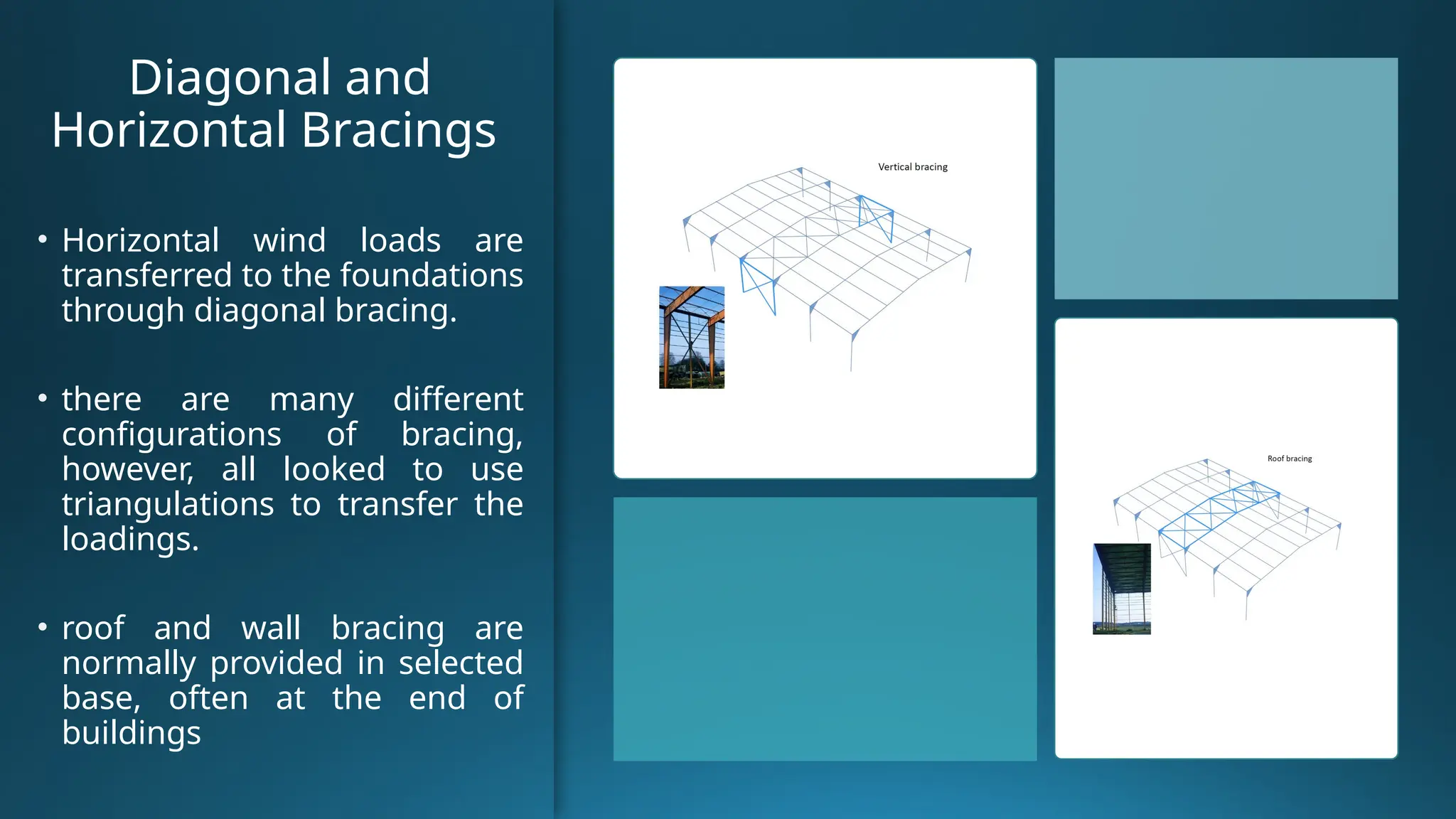
Diagonal and
Horizontal Bracings
•Horizontal wind loads are
transferred to the foundations
through diagonal bracing.
• there are many different
configurations of bracing,
however, all looked to use
triangulations to transfer the
loadings.
• roof and wall bracing are
normally provided in selected
base, often at the end of
buildings
12.
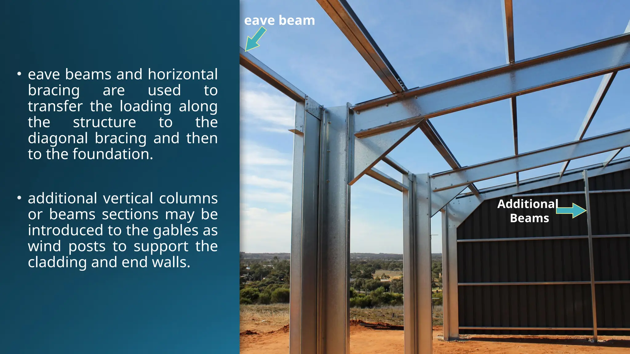
• eave beamsand horizontal
bracing are used to
transfer the loading along
the structure to the
diagonal bracing and then
to the foundation.
• additional vertical columns
or beams sections may be
introduced to the gables as
wind posts to support the
cladding and end walls.
eave beam
Additional
Beams
13.
Haunch Connections
• Apexconnections (rafter-to-rafter)
• Eaves connections (rafter-to-column)
• It cut from the rafter section and
extends for 10% of the span of the
eaves.
• Connection of the haunch rafter-to-
column is by an end plate.
Apex
Eave
14.
•The haunch isan
effective method of
locally increasing the
capacity of the rafter
at the points of
highest loading.
15.
For economy, connectionsshould be arranged to
minimize any requirement for additional
reinforcement.
This is generally achieved by:
• Making the haunch deeper (increasing the lever arms).
• Extending the eaves connection above the top flange of
the rafter.
• Adding bolt rows.
• Selecting a stronger column section.
16.
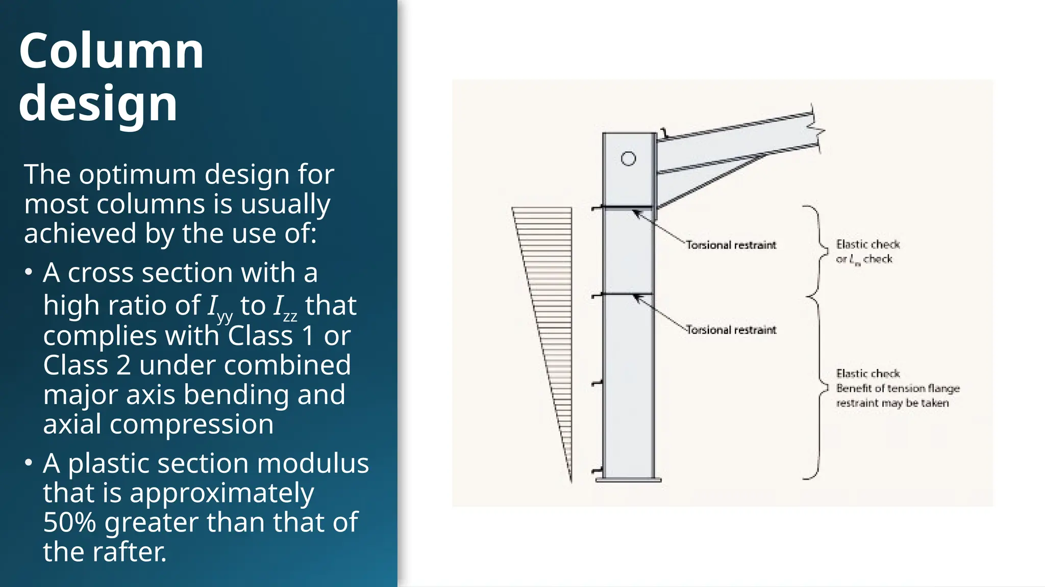
Column
design
The optimum designfor
most columns is usually
achieved by the use of:
• A cross section with a
high ratio of Iyy to Izz that
complies with Class 1 or
Class 2 under combined
major axis bending and
axial compression
• A plastic section modulus
that is approximately
50% greater than that of
the rafter.
17.
Column bases
• Inthe majority of cases,
a nominally pinned
base is provided,
because of the difficulty
and expense of
providing a rigid base.
• the foundation must
also resist the moment,
which increases costs
significantly compared
to a nominally pinned
base.
18.
Methods of structuralanalysis
• Elastic analysis
- Material is supposed to behave perfectly linear
elastic
• Plastic analysis
- Material non linearity is taken into account
- Redistribution of internal forces and moments
19.
Effects to betaken into account when significant
• Effects of deformed geometry (2nd order effects)
• Imperfections
• Stiffness of joints
• Ground-structure interaction
20.
First order andsecond order analysis
• First order analysis: performed on
the non deformed structure
• Second order analysis: performed
including effects of deformed
geometry
21.
Structural imperfections
• Dueto:
- lack of verticality
- lack of straightness
- eccentricities in joints
- residual stresses
- inhomogeneity of material
• Physical imperfection are replaced by equivalent geometric
imperfection.
Example of joints:
•The designer will probably choose the
assumption of rigid rafter-to-column
joints.
• The designer will probably choose the
assumption of either pinned or rigid
column bases.
25.
Conclusion
• Generally 2ndorder effects and imperfections have to be accounted
for in the design of portal frames.
• Depending on the value of αcr (factor by which the design loads would
have to be increased to cause elastic instability in a globalMode)
different calculation methods can be adopted.
• For portal frames it is convenient to account for global imperfection
and global 2nd order effects in the global analysis.
• Local 2nd order effects are generally included in the member
verification formulas of EN 1993-1-1 §6.3.
• Physical imperfections are replaced by either equivalent geometric
imperfections or equivalent loads.
• Bracing systems are subjected to external horizontal loads and loads
due to their function as stabilizing elements.
27.
The most commontypes of cranes
running on elevated runway
girders are:
• Top running bridge
cranes consisting of a
single or a double girder
spanning between the
end carriages.
• Underslung bridge
crane with special end
carriages where the
wheels are running on
the bottom flange of the
runway girders.
28.
Classification of thecranes is based on two factors:
• Frequency of use.
• State of loading (ratio of magnitude of actual or
assumed load to the safe working load).
29.
Crane Runway Girder
supportingtypes
• The maximum capacity
of cranes supported in
this manner is about
100kN as shown in (a).
• Above this capacity,
additional column may
required to increase
the depth of the
column below the
crane runway girder to
give adequate support
(b-d).
30.
The Crane
Runway Girder
andthe
Structure
• Seating for simply
supported crane girders
• Free rotation at the
supports of crane runway
girders is important in order
to prevent bending and
torsional moments in the
columns.
• Horizontal trussis
an effective restraint
to the crane
brackets to prevent
torsion in the
column.
33.
Various types of
railfastenings
• Providing a fastening to
restrain the rail in all
directions.
• The fastening of block
rails is always by welding.
• The fastening of specially
rolled rail sections is
normally obtained by a
fully rigid clamp or by
welding the rail to the
flange of the crane
runway girder.
Overhead
travelling cranes
actions
Vertical actions
•(1) The relevant vertical
wheel loads from a
crane on a runway
girder.
Note: The load to the
crane girder will be
maximum when trolley
wheels are closest to the
girder.
Overhead travelling cranesactions
Horizontal Forces
• (1) horizontal forces caused by acceleration
or deceleration of the crane in relation to its
movement along the runway beam.
• (2) Trolley in relation to its movement along
the crane bridge.
• (3) Horizontal forces caused by skewing of
the crane in relation to its m0vement along
the runway beam.
• (4) Buffer forces related to crane movement.
38.
Overhead travelling cranes
actions
Othertypes of actions
• Temperature actions.
• Loads on access walkways, stairs, platforms and guard rails
(vertically and horizontally).
• Accidental actions.
• Fatigue loads
39.
Design of thecrane runway girder
check
• (1) Major axis bending
• (2) Lateral torsional buckling
• (3) Horizontal moment capacity
• (4) Consider combined vertical and horizontal moments
• (5) Web shear at supports
• (6) Local compression under wheels
• (7) Web bearing and buckling under the wheel
• (8) Deflection
40.
Final Conclusion
1. Designthe crane runway girder for combined vertical and
lateral loads.
2. Determine the maximum crane load reactions on the (corbel
or the additional column) supporting the crane runway
beam and the coincident minimum crane load reactions on
the opposite portal column.
3. Determine the coincident lateral loads on the portal frame
due to oblique travel or lateral inertia.
41.
Final Conclusion
4. Addthe crane runway beam dead load to the main dead
load (above the main columns of the portal frame) , and
adding new load cases:
- Crane loads with maximum load at the left column.
- Crane loads with maximum load at right column.
- Lateral crane loads with maximum at left column and
acting
from left to right.
- Lateral crane loads with maximum at right column and
acting
from left to right.
42.
Final Conclusion
5. Determineload combinations.
6. Analyze the portal frame.
7. Check the deflections.
8. Check columns and rafter for strength