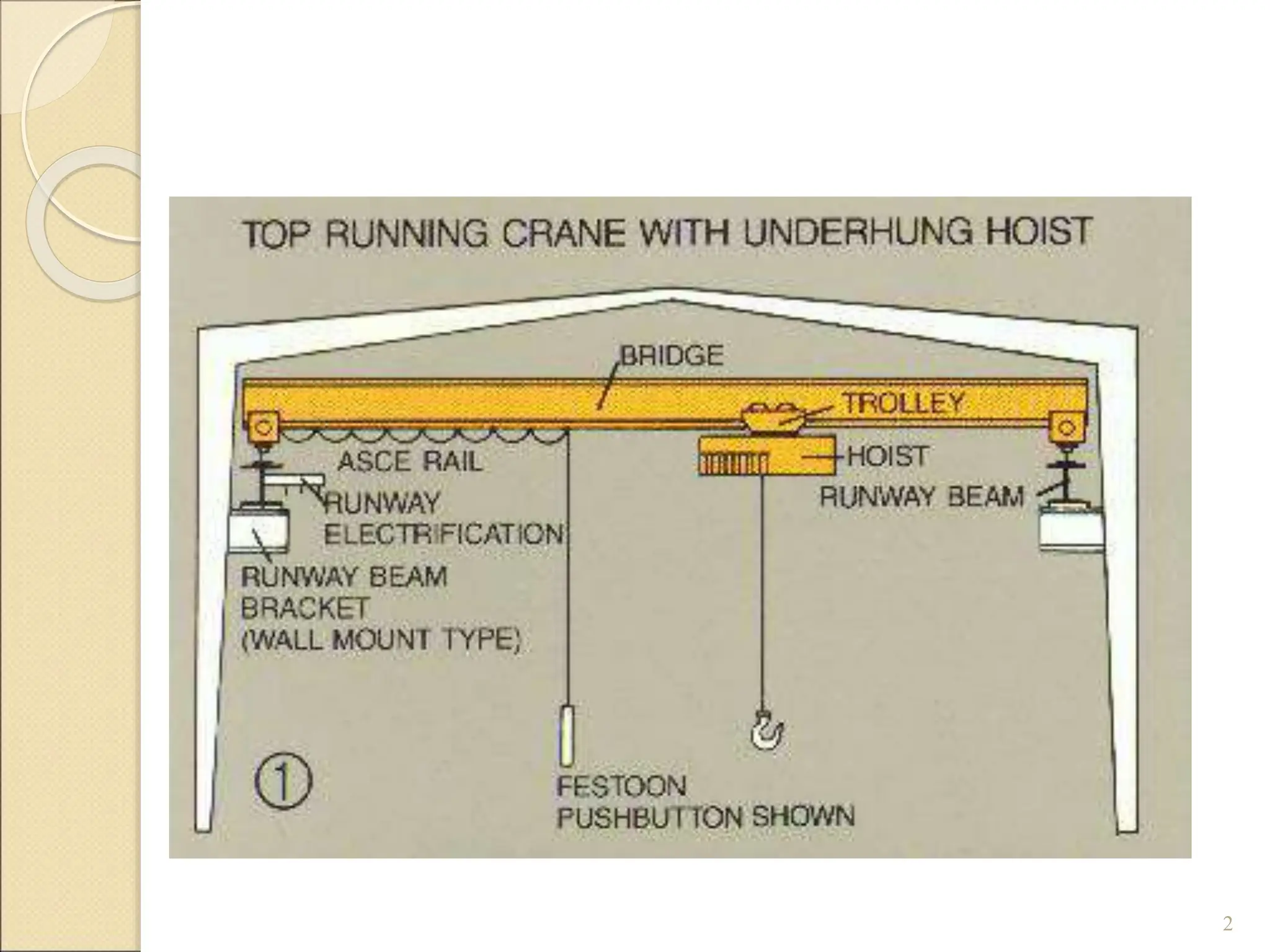
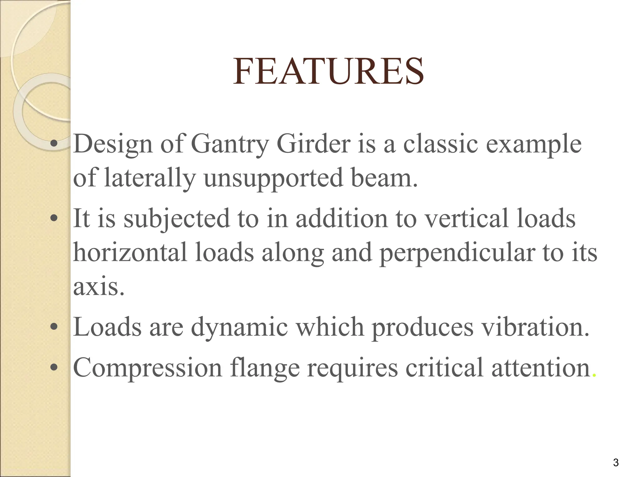
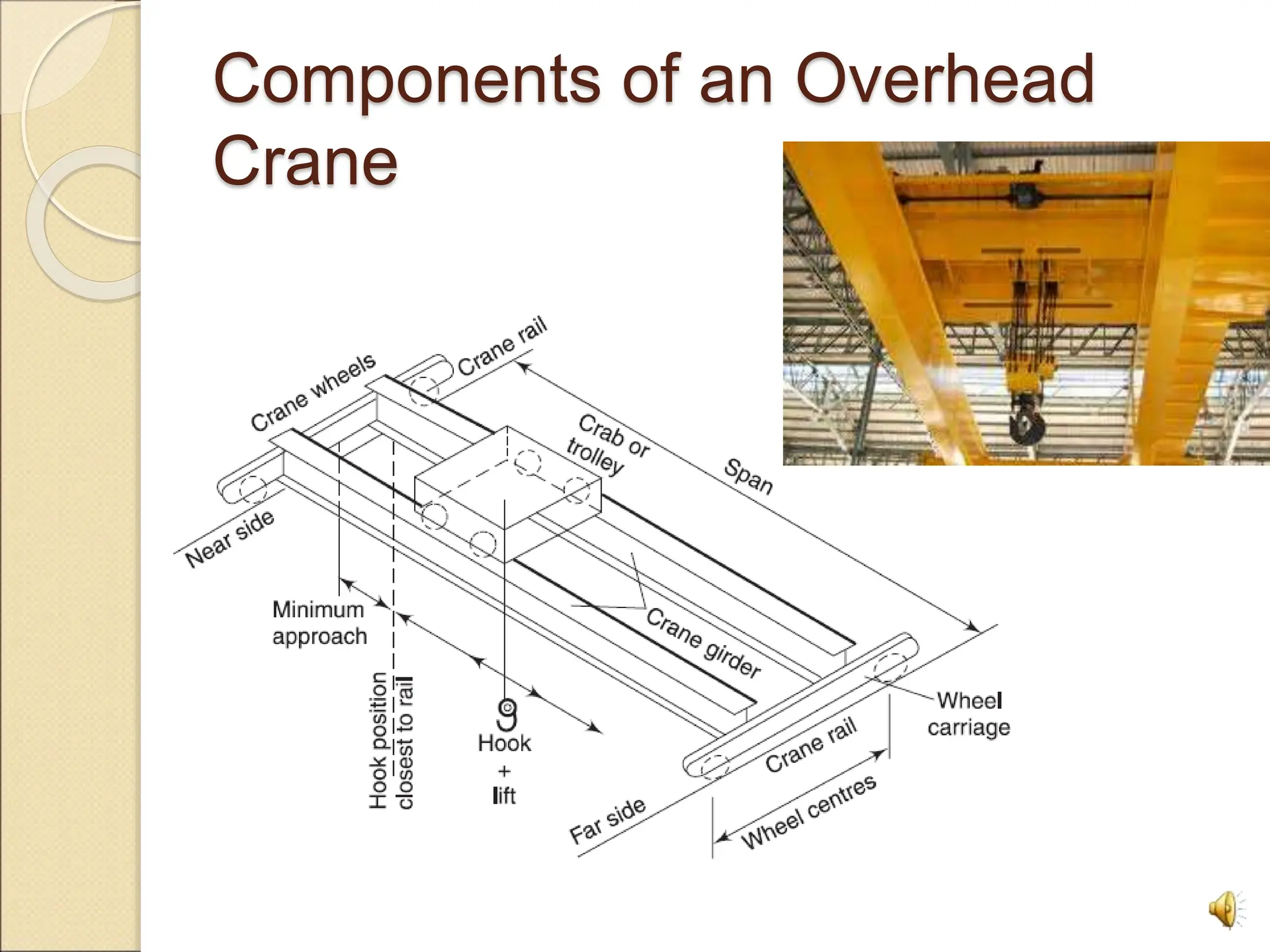
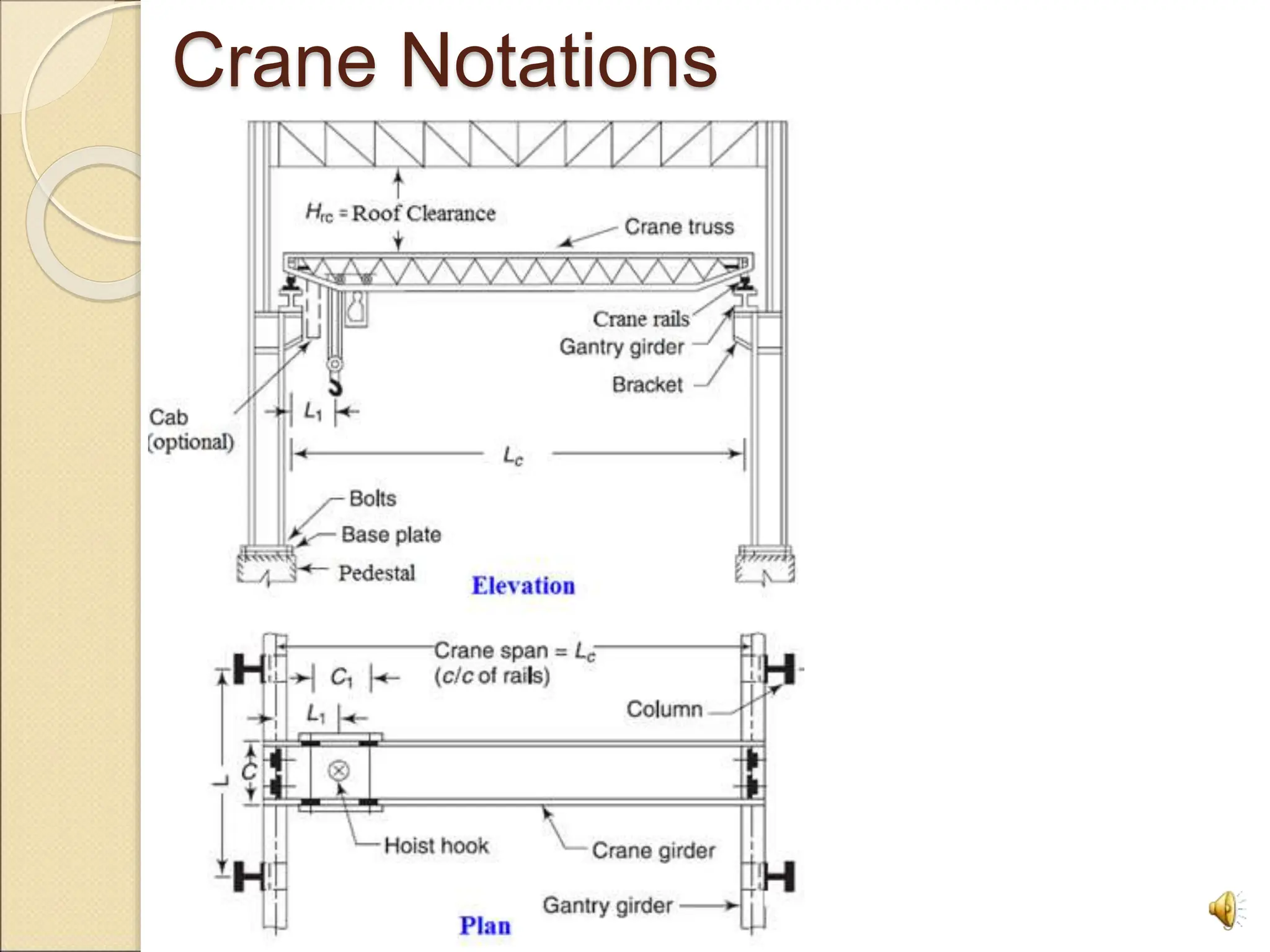
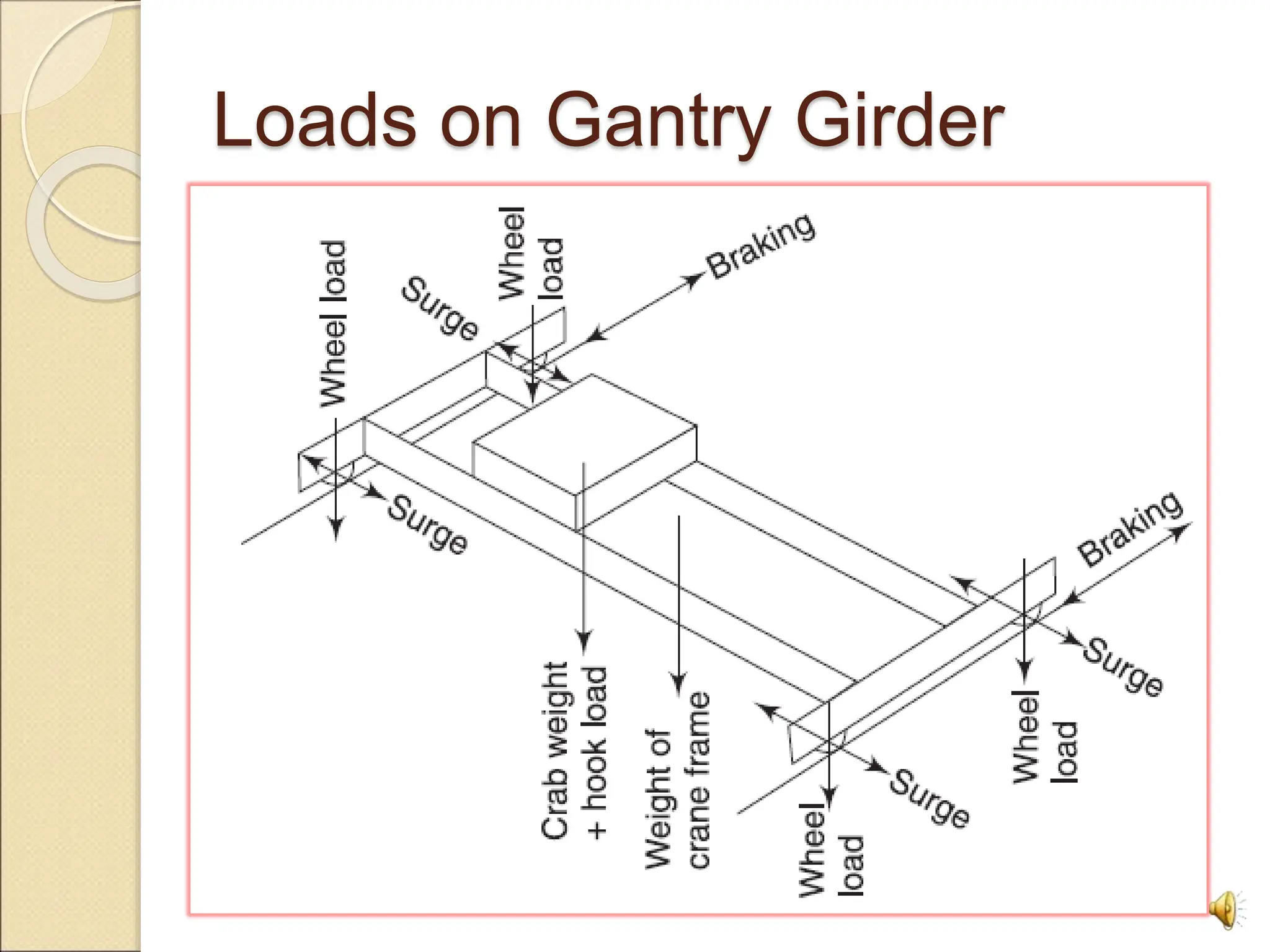
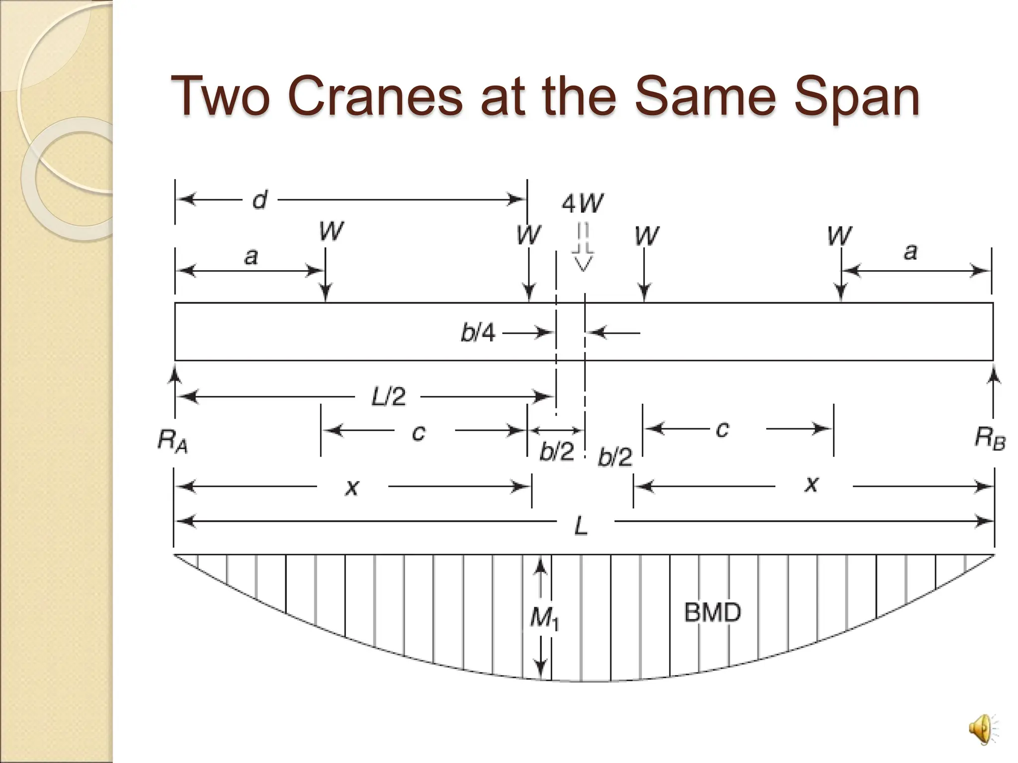
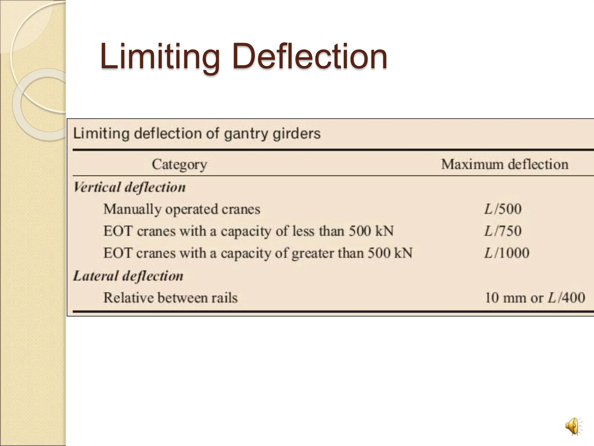
Design of Gantry Girders
1
2
3
FEATURES
• Design of Gantry Girder is a classic example
of laterally unsupported beam.
• It is subjected to in addition to vertical loads
horizontal loads along and perpendicular to its
axis.
• Loads are dynamic which produces vibration.
• Compression flange requires critical attention.
Components of an Overhead
Crane
4
Crane Notations
5
Loads on Gantry Girder
6
Maximum Load Effects
7
Max. S.F., B.M., and Deflection
8
Two Cranes at the Same Span
9
Max. BM for Two Cranes At the
Same Span
10
Limiting Deflection
11
Profiles Used for Gantry Girders
12
Steps for Design
 Assume that the lateral load is resisted entirely
by the top flange of the beam plus any
reinforcing plates, channels etc. and the
vertical load is resisted by the combined beam.
1. Find the maximum wheel load: This load is
maximum when the trolley is closest to the
gantry girder. Increase it for the impact
2. Calculate the maximum bending moment in
the gantry girder due to vertical loads.
3. To simplify the calculations, add the
maximum bending moment due to dead load
to the maximum wheel load moment
13
Steps for Design (cont.)
4. The maximum shear force is calculated. When the
gantry is not laterally supported, the following may
be used to select a trail section.
Zp = Mu / fy Zp (trial) = k Zp (k = 1.40-1.50)
Economic depth ≈ 1/12th of the span.
Width of flange ≈ 1/40 to 1/30th of the span
5. The plastic section modulus of the assumed
combined section
Mp = Zp fy
where Zp is called the plastic modulus
14
Steps for Design (cont.)
6. Check for moment capacity of the whole
section (as lateral support is provided at the
compression flange)
Mcz = βb Zp fy ≤ 1.2 Ze fy / γm0 <Mu
7. Check top flange for bending in both the axes
using the interaction equation
(My / Mndy)+ (M2/Mndz) ≤ 1.0
8. If the top (compression) flange is not
supported, Check for buckling resistance in the
same way as in step 6 but replacing fy with the
design bending compressive stress fbd.
15
Steps for Design (cont.)
9. Check web of the girder at points
of concentrated load for local
buckling or local crushing, and
provide load carrying/ bearing
stiffeners, if necessary.
10. Check for deflection under
working loads
16
17
 THANK YOU!

gantry girder.ppt

  • 1.
  • 2.
  • 3.
    3 FEATURES • Design ofGantry Girder is a classic example of laterally unsupported beam. • It is subjected to in addition to vertical loads horizontal loads along and perpendicular to its axis. • Loads are dynamic which produces vibration. • Compression flange requires critical attention.
  • 4.
    Components of anOverhead Crane 4
  • 5.
  • 6.
  • 7.
  • 8.
    Max. S.F., B.M.,and Deflection 8
  • 9.
    Two Cranes atthe Same Span 9
  • 10.
    Max. BM forTwo Cranes At the Same Span 10
  • 11.
  • 12.
    Profiles Used forGantry Girders 12
  • 13.
    Steps for Design Assume that the lateral load is resisted entirely by the top flange of the beam plus any reinforcing plates, channels etc. and the vertical load is resisted by the combined beam. 1. Find the maximum wheel load: This load is maximum when the trolley is closest to the gantry girder. Increase it for the impact 2. Calculate the maximum bending moment in the gantry girder due to vertical loads. 3. To simplify the calculations, add the maximum bending moment due to dead load to the maximum wheel load moment 13
  • 14.
    Steps for Design(cont.) 4. The maximum shear force is calculated. When the gantry is not laterally supported, the following may be used to select a trail section. Zp = Mu / fy Zp (trial) = k Zp (k = 1.40-1.50) Economic depth ≈ 1/12th of the span. Width of flange ≈ 1/40 to 1/30th of the span 5. The plastic section modulus of the assumed combined section Mp = Zp fy where Zp is called the plastic modulus 14
  • 15.
    Steps for Design(cont.) 6. Check for moment capacity of the whole section (as lateral support is provided at the compression flange) Mcz = βb Zp fy ≤ 1.2 Ze fy / γm0 <Mu 7. Check top flange for bending in both the axes using the interaction equation (My / Mndy)+ (M2/Mndz) ≤ 1.0 8. If the top (compression) flange is not supported, Check for buckling resistance in the same way as in step 6 but replacing fy with the design bending compressive stress fbd. 15
  • 16.
    Steps for Design(cont.) 9. Check web of the girder at points of concentrated load for local buckling or local crushing, and provide load carrying/ bearing stiffeners, if necessary. 10. Check for deflection under working loads 16
  • 17.