Download to read offline
![International Research Journal of Engineering and Technology (IRJET) e-ISSN: 2395-0056
Volume: 10 Issue: 03 | Mar 2023 www.irjet.net p-ISSN: 2395-0072
© 2023, IRJET | Impact Factor value: 8.226 | ISO 9001:2008 Certified Journal | Page 59
Design & Analysis of Crane Hook with Ansys
ANKIT KUMAR YADAV, PANKAJ SIDAR, BAPI BISWAS
(MECHANICAL ENGINEERING DEPARTMENT)]
Ankit Kumar Yadav (Vec Ambikapur)
Pankaj Sidar (Professor, Department Of Mechanical Vec Ambikapur)
Bapi Biswas (Professor, Department Of Mechanical Vec, Ambikapur)
Viswavidyalaya Engineering College Ambikapur, Sarguja Chhattisgarh Swami Vivekananda Technical University
(Csvtu) Bhilai, Chattisgarh
------------------------------------------------------------------------***-------------------------------------------------------------------------
ABSTRACT:-
Crane hook is very significant component for lifting the
load with the help of chain or links. Crane hooks are
highly liable and are always subjected to failure due to
the amount of stresses can ultimately lead to its failure.
To minimize the failure of crane hook, the stress induced
in it must be studied. A crane is subjected to continuous
loading and unloading. This may causes fatigue failure of
the crane hook. The review of previous enable to
conclude that components with complex geometry as
crane hooks require a more extensive investigation in
view of the fact that a very few articles have been
published so far regarding stress analysis of this curved
beam (crane hook).
Keywords:- crane Hook, design
1. INTRODUCTION OF CRANE
Crane hooks are always subjected to loads due to
accumulation of large amount of stresses which can
eventually lead to its failure. These are the components
which are generally used to elevate the heavy load in
industries and constructional sites. A crane is a machine,
equipped with a hoist, wire ropes or chains and sheaves
used to lift and move heavy material.
1.1 Used in Construction Field
A crane is a lifting machine principally works by the use
of pulleys and cables. For the construction industry,
these are valuable machines because they make working
with heavy machinery and construction materials
effectively.
The invention of cranes made things easy for humankind
because without them, loading, unloading, and lifting had
to be done by human hands, would consume more time,
and the entire system was not efficient at all. The ancient
Greeks invented the first construction crane hundreds of
years ago. Modern day construction cranes are huge,
taking up tons of material hundreds of meters in height.
For high end infrastructure projects, tower cranes are
used that have a reach as high as 800 meters.
Fig.1 Crane used in construction site
2. CRANE WORK
The reason for this research is, damage is one of the key
points toward the safety improvement. If a crack is
developed in the crane hook, mainly at stress
concentration areas, it can cause fracture of the hook and
lead to serious accidents. In ductile fracture, the crack
propagates continuously and is more easily detectable
and hence preferred over brittle fracture. In brittle
fracture, there is sudden propagation of the crack and
the hook fails eventually.
Fig.2Triangular cross-section Sketch](https://image.slidesharecdn.com/irjet-v10i308-230608055447-3c048f3f/75/Design-Analysis-of-Crane-Hook-with-Ansys-1-2048.jpg)
![International Research Journal of Engineering and Technology (IRJET) e-ISSN: 2395-0056
Volume: 10 Issue: 03 | Mar 2023 www.irjet.net p-ISSN: 2395-0072
© 2023, IRJET | Impact Factor value: 8.226 | ISO 9001:2008 Certified Journal | Page 61
( ) ( )
Rn = 92.6mm
(IV) Radius of centroidal axis = ( )
=
= 82
= 113 mm
(V) Distance between centroidal axis or neutral axis
E = – Rn = 113 – 92.6
=20.4 mm
Resultant stresses at inner surface(
M = p × Rn = p × 92.6
Hi= – = 92.6 – 82
=10.6 mm
H0 =R0 - Rn = 152 - 92.6 = 59.4
= +
= +
130=5.65 × 10⁻³ P
P = 35.5x10³ N
Resultant stresses at outer surface (σ0)
170 =1.4638 × 10⁻³ P
P = 63508 N
Load carrying capacity:
Taking lowest of two values given by equations the load
carrying capacity of crane hook is
P = 35.5 ×10³ N
ANSYS:-Ansys, Inc. is an American multinational
company with its headquarters based in Canonsburg,
Pennsylvania. It develops and markets CAE/metaphysics
engineering simulation software for product design,
testing and operation and offers its products and
services to customers worldwide. Ansys develops and
markets engineering simulation software for use across
the product life cycle. Ansys Mechanical finite element
analysis software is used to simulate computer models of
structures, electronics, or machine components for
analyzing the strength, toughness, elasticity,
temperature distribution, electromagnetism, fluid flow,
and other attributes. Ansys is used to determine how a
product will function with different specifications,
without building test products or conducting crash
tests.[5] For example, Ansys software may simulate how
a bridge will hold up after years of traffic, how to best
process salmon in a cannery to reduce waste, or how to
design a slide that uses less material without sacrificing
safety.Most Ansys simulations are performed using the
Ansys Workbench system,which is one of the company’s
main products. Typically Ansys users break down larger
structures into small components that are each modeled
and tested individually. A user may start by defining the
dimensions of an object, and then adding weight,
pressure, temperature and other physical properties.
Finally, the Ansys software simulates and analyzes
movement, fatigue, fractures, fluid flow, temperature
distribution, electromagnetic efficiency and other effects
over time. Ansys also develops software for data
management and backup, academic research and
teaching. Ansys software is sold on an annual
subscription basis.
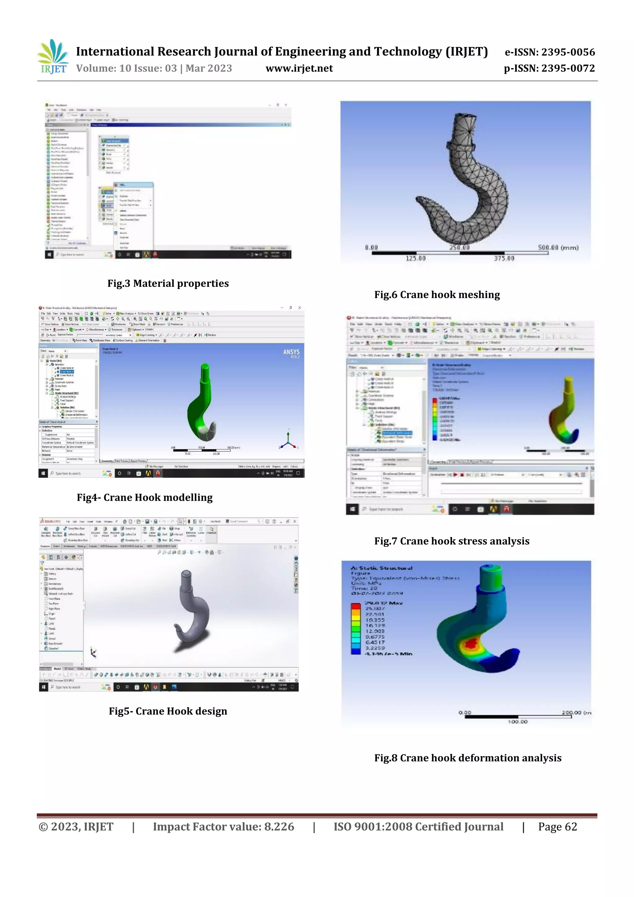
3. RESULT AND DISCUSSION:
A single point load (6 tons/ 63508N) is applied which is
equally distributed throughout the selected surfaces and
required results such as equivalent stress, strain and
total deformation is analyzed. The simulations process is
carried out by assigning four different materials having
different characteristics.
Table 1 Material properties](https://image.slidesharecdn.com/irjet-v10i308-230608055447-3c048f3f/75/Design-Analysis-of-Crane-Hook-with-Ansys-3-2048.jpg)
![International Research Journal of Engineering and Technology (IRJET) e-ISSN: 2395-0056
Volume: 10 Issue: 03 | Mar 2023 www.irjet.net p-ISSN: 2395-0072
© 2023, IRJET | Impact Factor value: 8.226 | ISO 9001:2008 Certified Journal | Page 63
Structural steel is a category of steel used for
making construction materials in a variety of shapes.
Many structural steel shapes take the form of an
elongated beam having a profile of a specific cross
section. Most steels used throughout Europe are
specified to comply with the European standard EN
10025. However, many national standards also remain in
force.
Structural steel material is the most feasible material as
compare to the other [ wrought iron, Structural steel &
Grey cast iron] because of its lowest Max.
Stress 250 MPa (as shown in graph).
Fig.9 Graph of stress and deformation
The simulation studies conducted on the crane hook
using the Alloy S355 for its sustainability against loading
gives the results such as Von Mises stress, Factor of
Safety (FOS), Strain and Displacements.
CONCLUSIONS:-
Structural steel material is the most feasible material
compared to wrought iron, & grey cast iron as it has
lowest maximum stress 250 MPa. The basic of structural
steel compair to other yield strength, toughness is
higher.We have successfully optimized the material of
the crane hook We have study the structural stresses of
hook by ANSYS R19.2 &o concluded that the material
which is having less deformation will have more stability
if less failure of crane hook. Final we got the material
Structural Steel with less deformation. So it is the
material suitable for crane hook.
REFERENCE
[1] Machine Design Book By V.B. Bhandari
[2] Design Data Book By PSG College of Technology
Coimbatore
[3]Govind Narayan Sahu, Narendra Yadav “Design and
stress analysis of various cross section of hook”
International Journal of Modern Engineering Research-
vol. 3, Issue. 4, Jul-Aug. 2013, pp-2187-2189, ISSN:
2249-6645
[4 ]Sayyedkasim Ali, Harish Kumar et al, “Analysis of
crane hook with different cross section using finite
element method”, International Journal of Science and
Research, ISSN (online): 2319-7064
[5]Cook, R., “Circumferential stresses in curved beams”,
Journal of Applied Mechanics-Transactions of ASME 59:
224-225, 1992
[6]Santosh Shau, Ritesh Dewangan et al, “ Study of Crane
Hook having trapezoidal section by finite element
method & design of experiments”, International Journal
of Modern Engineering Research-vol.2, Issue.4, July-Aug
2012, pp-2779-2781, ISSN: 2249-6645
[7] R .S. Khurmi,“Strength of materials” 23rd edition
Chapter 33 (2009)
[8]Yogeshtripathi, U.K.Joshi Comparision of stress
between Winkler Bach theory and Ansys finite element
method for crane hook with a trapezoidal cross-section
[9] Sushovan Ghosh, Biswaranjan Pati, Rohit Ghosh,
Ashutosh Palo and Dr. Rabindra Nath
Barman, Static Analysis of Crane Hooks with Different
Cross Sections A Comparative Study Using Ansys
Workbench. International Journal of Mechanical
Engineering andTechnology, 8(4), 2017, pp. 474–482.
[10]M.Amareswari Reddy1, M.N.V Krishnaveni, B.
Nagaraju, M RajaRoy4, Static Analysis of Crane Hook
with T-Section Using ANSYS, International Journal of
Engineering Trends and Technology (IJETT) – Volume 26
Number 2- August 2015
0
10000
20000
30000
40000
50000
60000
70000
0 100 200 300
LOAD
STRESS
Chart Title
Series1](https://image.slidesharecdn.com/irjet-v10i308-230608055447-3c048f3f/75/Design-Analysis-of-Crane-Hook-with-Ansys-5-2048.jpg)

This document describes a study analyzing the design and stresses in a crane hook using finite element analysis software (ANSYS). It summarizes the background and typical uses of cranes. It then details the analytical calculations and finite element modeling process used to analyze stresses in a crane hook under load. The study analyzed four different materials and determined that structural steel produced the lowest stresses and was therefore the most suitable material for the crane hook.


