1) The document describes improvements to the design of an engine crane, introducing a rotating mechanism using gears, an electric motor, and bearings to aid productivity, safety, and efficiency.
2) Calculations are shown for the gear design and specifications, shaft design, base plate load capacity, and bolt design to withstand the loads from lifting engines.
3) The new design uses bevel gears with a pitch diameter of 100mm and 600mm made of steel with an endurance strength of 55MN/m2. Calculations show the gear design can withstand the expected dynamic loads.
International Journal of Engineering Research and Applications (IJERA) is an open access online peer reviewed international journal that publishes research and review articles in the fields of Computer Science, Neural Networks, Electrical Engineering, Software Engineering, Information Technology, Mechanical Engineering, Chemical Engineering, Plastic Engineering, Food Technology, Textile Engineering, Nano Technology & science, Power Electronics, Electronics & Communication Engineering, Computational mathematics, Image processing, Civil Engineering, Structural Engineering, Environmental Engineering, VLSI Testing & Low Power VLSI Design etc.
Parametric Study on Curved Bridges Subjected to Seismic LoadingIRJET Journal
- The document presents a study on the behavior of curved bridges subjected to seismic loading. Two bridge types - box girder bridge and I-girder bridge - are modeled with varying radius of curvature (infinite, 150m, 250m) and column skewness (0, 15, 30 degrees).
- Linear static and non-linear pushover analyses are performed on the bridge models in CSI Bridge software. Modal periods and pushover curves are obtained and compared for different models.
- The results show that increasing the radius of curvature decreases the transverse vibration period. Increased skewness and smaller radii of curvature reduce the seismic resistance of the bridges as seen from decreased strength and stiffness in the pushover
IRJET- Finite Element Analysis of Slabs, Cross Girders and Main Girders in RC...IRJET Journal
This document summarizes a finite element analysis of T-beam bridge structures. The analysis varied parameters like bridge span (8m to 28m), slab size (3x2m to 5x4m), and slab depth (200mm to 300mm). Bridges were modeled in SAP2000 software and subjected to different live load standards (IRC Class AA Tracked, IRC Class 70R Tracked). Results showed bending moments, shear forces, and deflections increased with larger spans and live loads. The IRC Class AA loading produced the highest values. Slab and girder responses like maximum positive and negative bending moments were also presented.
IRJET- Seismic Analysis of Curve Cable-Stayed BridgeIRJET Journal
1) The document analyzes the seismic performance of cable-stayed bridges with different horizontal curvatures, ranging from straight to 5 degrees of curvature.
2) Six bridge models were analyzed using the software SAP2000, including a straight bridge and bridges with 1, 2, 3, 4, and 5 degrees of curvature.
3) The results show that base shear, pier displacement, and deck displacement all decreased as curvature increased from straight to 3 degrees, but then increased again from 3 to 5 degrees of curvature. The bridges with intermediate (2-3 degree) curvature demonstrated the best seismic performance.
The effect of varying span on Design of Medium span Reinforced Concrete T-bea...theijes
Bridge is a structure providing passageway over an obstacle without closing the way beneath. T-beam Bridge is mainly used by designer for small and medium span bridge. Reinforced Concrete is mostly used for highway bridge construction because of its durability, rigidity, economy, ease of construction and ease with pleasing appearance. This paper describes the design of 4-lane Reinforced Concrete T-beam Bridge deck considering IRC Class-AA tracked loading with span varying from 25 to 40m. After computing manually and STAAD Pro analysis software, it is observed that dead load bending moment with increasing span increases almost square of span
This document describes the design of a wall-mounted H-type jib crane with a maximum capacity of 1850 kg and a span of 7.25 meters. Key components include an H-beam structure, pivot assembly, manual trolley, motorized slewing, and a 68 kW hoist motor. Welding and structural analyses were conducted to ensure structural integrity under loading. Cost analyses were performed for the main components. The designed crane meets the client's specifications for lifting heavy loads in a manufacturing environment.
This document analyzes the effect of skew on stress resultants in T-beam bridges under various Indian Road Congress (IRC) loading conditions. T-beam bridge models with spans of 14m and varying skew angles from 0-45 degrees were modeled and analyzed using CSi Bridge software. The results show that bending moment, shear force, and torsion increase with higher skew angles and heavier loadings. Specifically, IRC AA tracked loading produces 10-15% higher bending moments than IRC 70R loading. IRC AA tracked and wheeled loadings also produce significantly different stress responses, with up to 40% variation. The analysis provides guidance on the behavior of skewed T-beam bridges under IRC standard loadings.
Analysis of outrigger system for tall vertical irregularites structures subje...eSAT Journals
Abstract The Analysis of the tall building is carried out to find the optimum position of outrigger system and belt truss by using lateral loads. The three dimensional model is considered and designed for the gravity load and placing of first and second position of the outrigger. Considering the design of Wind load is calculated by using IS 875 (Part 3) and Design of Earthquake load is calculated by using code IS 1893(part-1): 2000 in order to achieve reduction in drift, Deflection and story shear. The analysis is done by considering tall vertical irregularity of 30th storey of 7 X 7 bay for 1 to 10th storey and 7X6 bay 11th to 20th storey and 7X5 Bay 21st to 30th storey. Keywords: vertical irregularities, outrigger, linear static analysis Wind and earthquake load.
This document discusses stresses on composite girder bridges with square and skewed spans. It begins with an abstract that summarizes the study objectives, which are to analyze stresses on solid slab and composite deck arrangements under a 1t/m^2 load and investigate skew effects. The introduction provides background on composite construction using reinforced concrete slabs on steel girders. Key points made include that composite bridges experience less stress than solid slabs and that analysis will be done using STAAD-Pro software. The document then discusses the behavior and characteristics of skewed bridge decks compared to straight decks, noting increased stresses at obtuse corners and possible uplift at acute corners with higher skew angles.
Comparative analysis and design of box girder bridge sub structure with two diIAEME Publication
1) The document compares the design of a box girder bridge substructure according to the AASHTO and IRC codes.
2) It was found that the IRC code requires more reinforcement bars in the pile cap and piles compared to the AASHTO code for the same dimensions.
3) Finite element modeling using ANSYS showed greater displacement under load for the design according to the IRC code compared to AASHTO, indicating IRC provides more safety.
Comparative study on normal and skew bridge of psc box girdereSAT Journals
Abstract Nowadays the demand for high skew bridges has increased, and many bridge decks are built with some form of skew. The behavior of bridge is effected considerably with the presence of skew angle in bridge decks. In the present study an attempt has been made to study the skew bridge comparing with the normal bridge for skew angle 10, 20, 30, 40, 50. The finite element analysis is carried out for single span, two span and three span deck for dead load and moving load (IRC class 70R) loading using software SAP2000 ver.14. The results are presented in terms of displacement, bending moment and shear force. Keywords: Skew bridges, skew angle, PSC box girder, span length
A study on behaviour of outrigger system on high rise steel structure by vary...eSAT Journals
This study analyzed the behavior of an outrigger structural system on a 40-story steel structure by varying the depth of the outriggers. Three models were analyzed: with outrigger depth equal to full story height, 2/3 of story height, and 1/3 of story height. Lateral displacement and story drift were compared between a structure with a central braced core and each outrigger model. Results showed that providing additional outriggers and belt trusses reduced displacement and drift by up to 36.96% and 30.10% respectively. Reducing outrigger depth to 2/3 and 1/3 of story height resulted in only minor increases in displacement and drift compared to full height outriggers. The
This document provides information on the design of a T-beam bridge using the working stress method. It discusses the key components of a T-beam bridge including the deck slab, longitudinal girders, cross girders, abutments, and foundations. It also describes the design procedures for these components, focusing on the deck slab, cantilever slab, longitudinal girders, and cross girders. Methods for calculating bending moments and determining reinforcement are covered.
IJRET : International Journal of Research in Engineering and Technology is an international peer reviewed, online journal published by eSAT Publishing House for the enhancement of research in various disciplines of Engineering and Technology. The aim and scope of the journal is to provide an academic medium and an important reference for the advancement and dissemination of research results that support high-level learning, teaching and research in the fields of Engineering and Technology. We bring together Scientists, Academician, Field Engineers, Scholars and Students of related fields of Engineering and Technology.
1) The document discusses continuous welded rail (CWR) structures and the interaction between railway tracks and bridges. CWR reduces impact forces in the rails, increasing lifespan and improving ride quality.
2) Key considerations for CWR include buckling from high temperatures and fracture from low temperatures. Track-bridge interaction is also analyzed under various loads like temperature, traction, braking, and train forces.
3) Design requirements specify allowable stresses and displacements. Models are created to analyze stress and displacement considering load combinations through computational methods like finite element analysis.
This document discusses the design and analysis of a flat joint connection for a double wishbone suspension A-arm. It begins with identifying issues with the current round tube welded frame and motivates the redesign with a flat frame. The objectives are to design a customized A-arm for the flat joint, verify its sustainability with the joint, and standardize the wishbone A-arm design for the flat joint assembly. The A-arm and joint are modeled and analyzed using ANSYS to evaluate stress and deformation. The results show maximum stresses and deflections below allowable values, validating the new joint design which effectively transfers loads in working conditions.
Bus rollover accidents pose a serious safety risk, as the deforming bus body can threaten passenger lives. Simulation of bus rollovers is important to optimize bus body designs and ensure adequate strength. The simulation process involves creating a finite element model of the bus structure, applying kinematic conditions of a rollover, and measuring deformation to evaluate compliance with safety standards for intrusion into the passenger survival space. Factors like the center of gravity position, number and placement of pillars, material properties, and reinforcement can affect the bus's rollover performance.
The International Journal of Engineering & Science is aimed at providing a platform for researchers, engineers, scientists, or educators to publish their original research results, to exchange new ideas, to disseminate information in innovative designs, engineering experiences and technological skills. It is also the Journal's objective to promote engineering and technology education. All papers submitted to the Journal will be blind peer-reviewed. Only original articles will be published.
The papers for publication in The International Journal of Engineering& Science are selected through rigorous peer reviews to ensure originality, timeliness, relevance, and readability.
IRJET- Comparing the Load Pattern on Box Concrete Gridder with Consideration ...IRJET Journal
This document compares the load patterns on concrete box girders using the Indian Road Congress (IRC) code and American Association of State Highway and Transportation Officials (AASHTO) code. It models box girder bridges with varying spans from 10-50 meters in a structural analysis software. The analysis subjects the bridges to different vehicle load classes specified in the two codes and determines the resulting shear forces and bending moments. It finds that for 2-lane bridges, the IRC LM-1 load class produces the maximum shear force and AASHTO HL-93 produces the maximum bending moment. For 4-lane bridges, the AASHTO Class A load produces both the maximum shear force and bending moment.
This document describes the design and analysis of an integrated monocoque chassis for a 3-wheeled vehicle. The researchers modeled a new chassis in PRO-E and analyzed it using finite element analysis (FEA) in ANSYS. They selected 1.6mm thick cold rolled steel (CRS-D grade) based on the FEA results. The analysis checked for displacement and stresses under static loading conditions. The best design was identified as the one with minimum weight, maximum load capacity, and minimum deflection.
The document discusses the analysis and design of pre-stressed concrete sleepers used in railways. It covers the general functions of sleepers in providing support and transferring loads to the ballast bed. The most common types of pre-stressed sleepers are then described, including twin-block, longitudinal, and mono-block sleepers. Finally, the key design considerations for sleepers are outlined, such as loads from static and dynamic wheel forces, distribution of loads to the rail seat and ballast, and moments and stresses experienced by the sleeper.
Bridge loading and bridge design fundamentalsMadujith Sagara
This document discusses bridge loading standards and load evaluation for bridge design according to Eurocode standards. It provides definitions of key terms like carriageway and notional lane used in evaluating bridge loads. It summarizes the four load models specified in Eurocode 1-2 for determining effects of road traffic on bridges, including concentrated tandem loads and uniform loads in Load Model 1, single axle loads in Load Model 2, special abnormal vehicles in Load Model 3, and uniform crowd loads in Load Model 4. Diagrams show how these loads are applied to the notional lanes of a bridge carriageway for analysis. Groups of simultaneous traffic loads are also defined for combination with other actions.
Study of Different Parameters on the Chassis Space Frame For the Sports Car b...IOSR Journals
The concept of Finite Element Analysis of a chassis space frame has been highlighted in this project.
The topic has constrained the study of the chassis space frame. Complex assemblies are to be avoided, for
sports car. The model of the chassis space frame is built using CATIA V5 and then imported to ANSYS CLASSIC
11.0 to find its finite element module. To perform a torsion and Bending Test on the computational prototype
chassis to determine its torsional stiffness. To incorporate a design improvement study and note the effects on
the global torsional stiffness of the chassis. The stress ,strength and degrees of freedom of the chassis will be
investigated. The body shape is fixed and therefore the overall external shape of the chassis must not be altered.
The engine bay must remain as open as possible to allow a variety of engines to be fitted
This document provides an overview of spur gear design, including surface durability concepts, common failure modes, and equations for calculating contact stress. It discusses Buckingham's contact stress equation and modifications made by AGMA to account for factors like velocity, overload, and load distribution. Methods for determining the surface fatigue strength of gear materials are presented. Finally, common materials used for gears like cast iron, steel, and bronze are described.
An analysis of multi-storey building with floating and non-floating column un...IRJET Journal
1) The document analyzes the effects of floating columns in multi-storey buildings under seismic loading in different zones.
2) Static and equivalent static analyses were performed on models with and without floating columns to study structural response quantities like base shear, storey drift and displacements.
3) The results show that buildings with floating columns in seismic zones have increased displacements and decreased base shear and stiffness compared to buildings without floating columns. Floating columns are therefore not advisable in high seismic zones.
IRJET- Experimental Study on Behaviour of Strengthened R.C.C Column using Ext...IRJET Journal
The document presents an experimental study that investigated the behavior and load carrying capacity of reinforced concrete columns strengthened with external steel confinement. Four column specimens were tested: one unconfined conventional column, two confined with steel battens, and one with additional steel rods. The confined columns exhibited higher load capacities, energy absorption, and ductility than the conventional column. The top, middle, and bottom batten confinement provided the highest resistance to loading and failure initiated by buckling of the steel angles after yielding. The study demonstrated that external steel confinement can effectively strengthen reinforced concrete columns.
This document provides information about crane hooks. It begins by defining crane hooks and discussing their history. It then describes the main types of crane hooks, including single vs. double hooks, forging vs. laminated hooks, closed vs. semi-closed hooks, and electric rotary hooks. Applications of crane hooks are also outlined. Finally, the components of crane hooks are identified.
Design & Analysis of Crane Hook with AnsysIRJET Journal
This document describes a study analyzing the design and stresses in a crane hook using finite element analysis software (ANSYS). It summarizes the background and typical uses of cranes. It then details the analytical calculations and finite element modeling process used to analyze stresses in a crane hook under load. The study analyzed four different materials and determined that structural steel produced the lowest stresses and was therefore the most suitable material for the crane hook.
DESIGN OF MINE SHAFT ELEVATOR design guideSuresh Ramarao
This document discusses the design of a mine shaft elevator. It begins by providing background on the history and types of elevators. It then describes design considerations for mine shaft elevators, including options for shaft design (circular vs. horizontal) and parameters like speed, motor selection, suspension ropes, and guide rails. Calculations are shown for selecting these components for a case study mine shaft elevator with a lifting capacity of 32 tons and a height of 730 meters. Key parameters of the elevator design are presented in a table. The conclusions compare the computer-calculated design values to standard parameters.
The document presents a comparative study of different gantry girder profiles for various crane capacities and gantry spans. Bending moments, shear forces, and section properties are calculated and tabulated for 'I'-section with top and bottom plates, symmetrical plate girder, 'I'-section with 'C'-section top flange, plate girder with rolled 'C'-section top flange, and unsymmetrical plate girder sections. Graphs of steel weight required per meter length are presented. The 'I'-section with 'C'-section top flange profile is found to be optimized for biaxial bending but rolled sections may not be available for all spans.
IRJET- Development of Winch Machine For Erection of Transmission Tower –A ReviewIRJET Journal
This document reviews the development of a winch machine for erecting transmission towers. It begins with an introduction to winch machines and their components. It then discusses three common methods for tower erection - manual, motorized winch, and helicopter - and their limitations. The document conducts a literature review on winch design improvements and analyses components like drums and ropes. It concludes that a specially designed tractor PTO-driven winch could help overcome limitations and increase safety during tower erection.
Study of Roller Conveyor Chain Strip under Tensile Loading IJMER
Conveyor chain drives are one of the primary systems used in industry to transmit power and
convey products. Conveyor chain that suffers from premature elongation due to wear and needs to be
replaced on a frequent basis will negatively impact productivity and increase the cost of the operation.
Roller conveyor chains are the critical component in sugar mills, paper mill, food processing, fertilizer
industry, pharmaceutical industry, cement industry, foundry industry, heat treatment units, coal mines
etc. The scope of this paper is to study the behavior of chain strip under tensile loading. In turn it will
help in reducing down time and maintenance cost related chain assembly in various above said
industries. Today, few literatures on the wear of conveyor chain are available. In this paper we study the
analytical, experimental and numerical behavior of strip under tensile loading.
Review of shaft failure in Coil Car AssemblyIRJET Journal
This document summarizes a study on failures of shafts in coil car assemblies. The researchers investigated a failed coil car shaft and found that reversed bending fatigue caused it to fracture, occasionally due to misalignment. They calculated loads on the existing shaft theoretically and analytically and found the stresses exceeded permissible levels, indicating it was prone to failure. To improve shaft design, they examined increasing diameter and using fillets/chamfers to disperse stresses. A literature review showed other shaft failures were due to low radius of curvature, incorrect chamfer size increasing stress concentration, and vibrations from imbalance.
Influence of RC Jacketing on seismic vulnerability BridgesIRJET Journal
This document analyzes the influence of retrofitting reinforced concrete bridge columns on the seismic performance of bridges. Finite element models of box-girder bridges with varying column sizes (0.54m x 0.54m, 1m x 1m, 1.2m x 1.2m) and skew angles (30°, 45°, 60°) were created and analyzed using time history analysis. Retrofitting the columns by increasing their size decreased the natural frequency and increased the time period of the bridges. It also decreased the base shear, reducing the seismic demand on the bridges. Larger column sizes of 1m x 1m and 1.2m x 1.2m provided more strength and stiffness, improving the
This document describes the design optimization of a floor crane. The original crane design had high deflection and bending moment issues. To address this, the researchers reduced the length of the second column from 1.2m to 1m, lowering the crane's reach from the floor. Various analyses showed the optimized design had lower deflection, bending moment, rope tension, and performed better under accelerated loads. The optimized crane was then fabricated and shown to be safer, stronger, and require less material.
Design, Simulation and Optimization of Multitubublar Rollcage of an All Terra...IRJET Journal
This document describes the design, simulation, and optimization of a multi-tubular rollcage for an all-terrain vehicle. The researchers created a 3D model of a rollcage in SOLIDWORKS and analyzed it using ANSYS to evaluate stress distribution and displacement under loading conditions. Their goal was to design a rollcage that provides structural strength and safety protection for the driver while keeping the overall weight low. They considered different pipe materials and cross-sections, selecting chrome molybdenum steel pipes with an outer diameter of 31.75mm and wall thickness of 1.65mm as the optimal design based on its high bending strength and stiffness but low weight.
D ESIGN AND A NALYSIS OF D UMP B ODY ON T HREE W HEELED A UTO V EHICLEIJCI JOURNAL
This document describes the design and analysis of a dump body for a three-wheeled auto vehicle. It discusses designing a dump body with a capacity of 750kg to be mounted on a three-wheeled vehicle. The dump body is modeled using PRO/E CAD software. A finite element analysis is performed on the dump body model in ANSYS to analyze stresses from the payload weight. Three dump body designs are analyzed made of mild steel, aluminum, and a combination of both. The aluminum body showed the highest deformation of 0.37482mm while the mild steel body showed the lowest at 0.13862mm, both within allowable limits. The document presents results on deformations and stress intensities for each body design.
Designing paper straw bridge (lightest at ARU - 2.1g). Designing in inventor, Finite Element Modelling and Analysis - ANSYS , Stiffness matrix and constructing a final product.
Dimensional Optimization of Helical Springs Used in Tractor Seat by FEA and E...IRJET Journal
This document discusses dimensional optimization and failure analysis of helical springs used in tractor seats through finite element analysis (FEA) and experimental testing. It aims to reduce stresses on helical springs under dynamic loading conditions typically experienced in tractor seats.
The study examines the current design of tractor seat helical springs and performs FEA stress analysis, fatigue life analysis, and experimental testing. It also proposes a new spring configuration for the tractor seat to improve spring performance. Results from analytical stress calculations, FEA stress modeling, and experimental fatigue testing of tension and compression springs are presented and compared to evaluate which spring design provides better stress distribution and longer fatigue life.
International Journal of Engineering Research and Applications (IJERA) is an open access online peer reviewed international journal that publishes research and review articles in the fields of Computer Science, Neural Networks, Electrical Engineering, Software Engineering, Information Technology, Mechanical Engineering, Chemical Engineering, Plastic Engineering, Food Technology, Textile Engineering, Nano Technology & science, Power Electronics, Electronics & Communication Engineering, Computational mathematics, Image processing, Civil Engineering, Structural Engineering, Environmental Engineering, VLSI Testing & Low Power VLSI Design etc.
Dynamic analysis of a reinforced concrete horizontal curved beam using softwareeSAT Journals
Abstract
Dynamic analysis of a reinforced concrete beam bridge, horizontally curved in plan is done using a finite element software. The
support conditions considered are simple supports. Dynamic loading in the form of moving vehicular load is taken into account
for the purpose of analysis. IRC Class AA type of vehicle is simulated on two lanes on the beam of span 31m, having a box type
cross-section. A parametric study is done varying the radius of curvature of the beam from 50 m to 250 m with the interval of 50
m to check the behavior of the beam. Various responses of the beam like bending moment, shear force, torsional moment and
deflection are calculated. The influence of a non-dimensional parameter L/R i.e. ratio of length of the beam to radius of curvature
of the beam is verified for the responses of the beam. From the results, it has been found that the responses i.e. the bending
moment, shear force, torsional moment and deflection of the beam decrease as the radius of curvature of the beam in increased.
Also, the responses of the beam increase as the L/R ratio is increased.
Keywords: Dynamic analysis, horizontally curved beam, finite element, moving vehicular moving load, Simply
Supported, Box type, parametric study, L/R ratio
Analysis of main beam of bridge crane based on ANSYSIJRES Journal
In this paper, the beam of bridge crane is the research object. This paper introduced the main
structure of the bridge crane. Four kinds of work conditions are studied, and a finite condition analysis is
carried out based on ANSYS. According to the actual operating results and theoretical analysis on allowable
bending and allowable stress this paper confirmed that the stiffness safety of beam meets the design
requirements, and provided reliable basis and optimization of crane design.
This paper introduces a two dimensional bridge deck for a cantilever bridge with a 15 m long span that has been modelled and analysed using computational modelling software (LUSAS) to obtain maximum moments and
shear forces. The significance of the problem is to determine the worst scenario case within the deck in terms of highest
bending moment and shear force, for example, the most affected parts of deck under load. The problem was tackled
with the aid of LUSAS Bridge Plus which is part of LUSAS software package. Generally, LUSAS Bridge Plus works
by analysing equations and allowing combinations of load case results.
International Journal of Engineering Research and Applications (IJERA) is an open access online peer reviewed international journal that publishes research and review articles in the fields of Computer Science, Neural Networks, Electrical Engineering, Software Engineering, Information Technology, Mechanical Engineering, Chemical Engineering, Plastic Engineering, Food Technology, Textile Engineering, Nano Technology & science, Power Electronics, Electronics & Communication Engineering, Computational mathematics, Image processing, Civil Engineering, Structural Engineering, Environmental Engineering, VLSI Testing & Low Power VLSI Design etc.
IRJET- Design and Analysis of River Bridge Deck Slab at Vangani-Karav-PashaneIRJET Journal
This document summarizes the design and analysis of a river bridge deck slab located at Vangani-Karav-Pashane. The researchers designed a simple reinforced concrete deck slab using the working stress method and verified the results using STAAD.pro software. Key aspects of the design included considering IRC Class A loading, proposing a two-lane deck slab with a 6.8m carriageway width, and analyzing stresses, shear forces, and moments on the slab. Manual calculations were performed and compared to STAAD results. The design aimed to facilitate easy commuting across the Ulhas River by replacing a deteriorating existing bridge deck.
The document describes the design and fabrication of a flexible gravity conveyor. It discusses how gravity conveyors use rollers to transport lightweight packaged materials by utilizing the force of gravity. The conveyor's main advantages are its flexibility, portability, and ease of use. The document provides details on the conveyor's components, design calculations, applications, and concludes that with further refinement, this type of conveyor could be produced at low cost for transporting items up inclined surfaces.
Your One-Stop Shop for Python Success: Top 10 US Python Development Providersakankshawande
Simplify your search for a reliable Python development partner! This list presents the top 10 trusted US providers offering comprehensive Python development services, ensuring your project's success from conception to completion.
Introduction of Cybersecurity with OSS at Code Europe 2024Hiroshi SHIBATA
I develop the Ruby programming language, RubyGems, and Bundler, which are package managers for Ruby. Today, I will introduce how to enhance the security of your application using open-source software (OSS) examples from Ruby and RubyGems.
The first topic is CVE (Common Vulnerabilities and Exposures). I have published CVEs many times. But what exactly is a CVE? I'll provide a basic understanding of CVEs and explain how to detect and handle vulnerabilities in OSS.
Next, let's discuss package managers. Package managers play a critical role in the OSS ecosystem. I'll explain how to manage library dependencies in your application.
I'll share insights into how the Ruby and RubyGems core team works to keep our ecosystem safe. By the end of this talk, you'll have a better understanding of how to safeguard your code.
Let's Integrate MuleSoft RPA, COMPOSER, APM with AWS IDP along with Slackshyamraj55
Discover the seamless integration of RPA (Robotic Process Automation), COMPOSER, and APM with AWS IDP enhanced with Slack notifications. Explore how these technologies converge to streamline workflows, optimize performance, and ensure secure access, all while leveraging the power of AWS IDP and real-time communication via Slack notifications.
zkStudyClub - LatticeFold: A Lattice-based Folding Scheme and its Application...Alex Pruden
Folding is a recent technique for building efficient recursive SNARKs. Several elegant folding protocols have been proposed, such as Nova, Supernova, Hypernova, Protostar, and others. However, all of them rely on an additively homomorphic commitment scheme based on discrete log, and are therefore not post-quantum secure. In this work we present LatticeFold, the first lattice-based folding protocol based on the Module SIS problem. This folding protocol naturally leads to an efficient recursive lattice-based SNARK and an efficient PCD scheme. LatticeFold supports folding low-degree relations, such as R1CS, as well as high-degree relations, such as CCS. The key challenge is to construct a secure folding protocol that works with the Ajtai commitment scheme. The difficulty, is ensuring that extracted witnesses are low norm through many rounds of folding. We present a novel technique using the sumcheck protocol to ensure that extracted witnesses are always low norm no matter how many rounds of folding are used. Our evaluation of the final proof system suggests that it is as performant as Hypernova, while providing post-quantum security.
Paper Link: https://eprint.iacr.org/2024/257
Fueling AI with Great Data with Airbyte WebinarZilliz
This talk will focus on how to collect data from a variety of sources, leveraging this data for RAG and other GenAI use cases, and finally charting your course to productionalization.
GraphRAG for Life Science to increase LLM accuracyTomaz Bratanic
GraphRAG for life science domain, where you retriever information from biomedical knowledge graphs using LLMs to increase the accuracy and performance of generated answers
Trusted Execution Environment for Decentralized Process MiningLucaBarbaro3
Presentation of the paper "Trusted Execution Environment for Decentralized Process Mining" given during the CAiSE 2024 Conference in Cyprus on June 7, 2024.
Salesforce Integration for Bonterra Impact Management (fka Social Solutions A...Jeffrey Haguewood
Sidekick Solutions uses Bonterra Impact Management (fka Social Solutions Apricot) and automation solutions to integrate data for business workflows.
We believe integration and automation are essential to user experience and the promise of efficient work through technology. Automation is the critical ingredient to realizing that full vision. We develop integration products and services for Bonterra Case Management software to support the deployment of automations for a variety of use cases.
This video focuses on integration of Salesforce with Bonterra Impact Management.
Interested in deploying an integration with Salesforce for Bonterra Impact Management? Contact us at sales@sidekicksolutionsllc.com to discuss next steps.
Skybuffer SAM4U tool for SAP license adoptionTatiana Kojar
Manage and optimize your license adoption and consumption with SAM4U, an SAP free customer software asset management tool.
SAM4U, an SAP complimentary software asset management tool for customers, delivers a detailed and well-structured overview of license inventory and usage with a user-friendly interface. We offer a hosted, cost-effective, and performance-optimized SAM4U setup in the Skybuffer Cloud environment. You retain ownership of the system and data, while we manage the ABAP 7.58 infrastructure, ensuring fixed Total Cost of Ownership (TCO) and exceptional services through the SAP Fiori interface.
Programming Foundation Models with DSPy - Meetup SlidesZilliz
Prompting language models is hard, while programming language models is easy. In this talk, I will discuss the state-of-the-art framework DSPy for programming foundation models with its powerful optimizers and runtime constraint system.
In the realm of cybersecurity, offensive security practices act as a critical shield. By simulating real-world attacks in a controlled environment, these techniques expose vulnerabilities before malicious actors can exploit them. This proactive approach allows manufacturers to identify and fix weaknesses, significantly enhancing system security.
This presentation delves into the development of a system designed to mimic Galileo's Open Service signal using software-defined radio (SDR) technology. We'll begin with a foundational overview of both Global Navigation Satellite Systems (GNSS) and the intricacies of digital signal processing.
The presentation culminates in a live demonstration. We'll showcase the manipulation of Galileo's Open Service pilot signal, simulating an attack on various software and hardware systems. This practical demonstration serves to highlight the potential consequences of unaddressed vulnerabilities, emphasizing the importance of offensive security practices in safeguarding critical infrastructure.
leewayhertz.com-AI in predictive maintenance Use cases technologies benefits ...alexjohnson7307
Predictive maintenance is a proactive approach that anticipates equipment failures before they happen. At the forefront of this innovative strategy is Artificial Intelligence (AI), which brings unprecedented precision and efficiency. AI in predictive maintenance is transforming industries by reducing downtime, minimizing costs, and enhancing productivity.
Presentation of the OECD Artificial Intelligence Review of Germany
A0290109
1. Research Inventy: International Journal Of Engineering And Science
Vol.2, Issue 9 (April 2013), Pp 01-09
Issn(e): 2278-4721, Issn(p):2319-6483, Www.Researchinventy.Com
1
Improvement in the Design of Engine Crane for Modern
Industries
1,
Adzimah, Stephen Kwasi, 2,
Akinwonmi, Ademola Samuel 3,
Bentum-Mensah,
Benedict
1, 2, 3
Department Of Mechanical Engineering University Of Mines and Technology, Tarkwa, Ghana
Abstract - This paper presents an improvement in the design of engine crane, introducing a rotating
mechanism comprising a gearing system, electric motor, solid shaft with flange, sleeve bearing, and a support
bearing. The precision cut gears used are made of steel with endurance strength of 55 MN/m2
(according to the
American Gear Manufacturers Association (AGMA). In the design, the limiting endurance load of 17.06 KN and
the limiting wear load of 22.96 KN are greater than dynamic load of 10.83 KN which implies the design is
satisfactory from the standpoint of wear, dynamic and endurance loads. Since the use of cranes is indispensable
in the industry, the design will aid productivity, safety of workers, ergonomics, efficiency, effectiveness and
versatility of the cranes, for which they are designed and manufactured.
Keywords: design, dynamic load, engine crane, limiting endurance, rotating mechanism
1. INTRODUCTION
Cranes are a complex combination of simple machines. Basically, a lever is used to crank a line of
cable through a pulley, or system of pulleys, to lift heavy objects. The first cranes were invented by the Ancient
Greeks and were powered by men or animals, such as donkeys. The cranes built by the Ancient Greeks were
typically made with wood and rope, and anchored into the ground with large stakes. These cranes were used for
the construction of tall buildings. The archaeological record shows that no later than 515 BC, distinctive cuttings
for both lifting tongs and Lewis irons began to appear on stone blocks of Greek temples. Since these holes point
at the use of a lifting device, and since they are to be found either above the centre of gravity of the block, or in
pairs equidistant from a point over the centre of gravity, they are regarded by archaeologists as the positive
evidence required for the existence of the crane. The heyday of crane in ancient times came under the Roman
Empire, when construction activity soared and buildings reached enormous dimensions. The Romans adopted
the Greek crane and developed it further. The simplest Roman crane consisted of a single-beam jib, a winch, a
rope and a block containing three pulleys. Having thus a mechanical advantage of 3:1, it has been calculated that
a single man working with the winch could raise 150 kg (3 pulleys x 50 kg = 150 kg), assuming that 50 kg
represents the maximum effort a man can exert over a longer time period.
Today crane parts are made of different types of metals, heavy-duty cables, and can lift and move
objects many times heavier than the loads of ancient times. In olden times, thousand of slaves had to be arranged
whenever a heavy load had to be lifted or dragged Khurmi, (2009). Moving these objects involves some
interesting physics. The load is attached to the end of the cable, and then cranked along pulleys to whatever
height necessary. The most fun lies in the smallest piece, the pulley. This wonderful, simple machine reduces
the force of the weight of an object, and allows less force to be used to move it than would be necessary with
direct force, such as pushing it up a ramp. The pulley divides the weight, spreads it out along the cables, and
multiplies the force being used to lift the object. The perfect condition for this is a pulley with zero friction and
cables that do not stretch. While currently impossible to reach these conditions, technology has gotten much
closer than the Ancient Greeks with their ropes and wooden pulleys. Now, with new materials and powerful
motors, cranes can be used to lift much heavier objects than ever before. In any industry, time spent in doing a
particular work is very important to management. The safety of workers can never be ruled out. Crane accidents
and emergencies are occurring with increasing frequencies in ports around the world. This is understandable
due to rapidly increasing population of cranes, increasing crane dimensions resulting in reducing visibility and
operator control, frequent adverse weather conditions, and also crane maintenance and operating procedures not
keeping up with increasing risks and demands of a fast paced modern terminal Larry, (2007). When all the
forces that act on a given part are known, their effect with respect to the physical integrity of the part still must
be determined Leonardo and George, (1995). It would therefore be reasonable to suppose that fatigue failure due
to lack of allowance do not occur Raymond, (1990). On 21st May 2000 the top of a tower crane collapsed at
Canada Square in the Canary Wharf area of East London. Tragically, three of the erection crew died in the
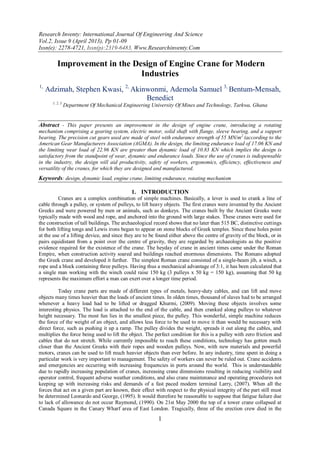
2. Improvement In The Design Of Engine Crane…
2
collapse. The collapse occurred near the end of an operation to raise the height of the tower crane with an
external climbing or jacking frame. The Health and Safety Executive (HSE) understands that at that time this
was only the second collapse of a tower crane during climbing anywhere in the world. The first occurred in San
Francisco on 28th November 1989. In the automobile industry for example, the engine crane is used to lift and
mount car engines and other dexterous components during repair works or servicing. In a modernized
automobile workshop, damaged engines are kept in a spacious room allocated for such purposes until vehicle
owners approve of their state. Dismantling and cleaning of the entire engine is also carried out in this same
room. As the damaged engines pile up in the room, there is the need to sell them to scrap dealers. Some
technicians are made to halt their work in order to help load these damaged engines into a light duty truck.
Lifting of such heavy objects, whose edges are sharp, with the hands, is very dangerous. The involvement of
technicians who are busy on their job, are deplored to the loading, which is time wasting. The objective of this
paper is therefore to create an improvement on the existing engine crane in order to aid productivity, safety of
workers, ergonomics, efficiency and effectiveness, usefulness and versatility of the cranes, for which they are
designed and manufactured.
II. MATERIALS AND METHOD
2.1 Design Features of Existing Crane
Figure 1 shows the existing design of the engine crane. For some designs, the upright support or
column is inclined with reference to transverse load supporting member.
Fig.1 Existing Design of an Engine Crane
U p rig h t S u p p o rt
F la n g e
S h a ft
S le e v e B e a rin g
S u p p o rt b e a rin g
C a s te r W h e e l
Fig. 2 Front View of the Rotating Mechanism of the Proposed Design
3. Improvement In The Design Of Engine Crane…
3
Fig. 3 Pictorial View the Proposed Design
2.2 Design Calculations and Analysis
2.3 Rotating Mechanism (design of gears employed)
Two cast iron bevel gears of endurance strength of 55 MN/m2
having pitch diameters of 100 mm and
600 mm respectively were used. The tooth profiles are of composite form are selected to avoid
interference of the meshing gears.
2.4 Design for strength for the bevel gears
The pinion is the weaker gear since both the gear and pinion are of the same material. Therefore design
will be based on the pinion. Since the diameters of the gears are known, the Lewis equation (1) below will be
applied
………………………………………………………………………….. (1)
where
m = module based on the largest tooth cross section.
y = form factor based on the formative number or the teeth and type of tooth profile.
b = the face width of the gear,
s = allowed stress
F = the permissible force that may be transmitted
L = cone distance …………………………………………………… (2)
RP = pitch radius of pinion, Rg = pitch radius of gear
Face width b .
Pitch line velocity V
Where, 0.157 m/s
Power Torque angular velocity
Force transmitted F V 9004.56 N
Endurance strength s = 53.598 MN/m2
From equation 1,
, allowable
Assuming form factor
= 5.259 m
4. Improvement In The Design Of Engine Crane…
4
Number of teeth of pinion
Formative number of pinion teeth Nf (pinion) = Np/Cos αp;
Cos αp . Also,
Number of teeth of gear
Formative number of gear Nf (gear) = Ng/ Cos αg
Cos αg
Values of standard modules in millimeters, taken from ISO/R54:
Preferred: 1, 1.25, 1.5,2, 2.5,3, 4,5,6,8,10,12,16,20,25,40,50,
Second Choice: 1.125,1.375,1.75,2.25,2.75,3.5,34.5,5.5,7,9,11,14,18,22,28,36,45,
From the values of the standard modules, we will try preferred module m = 1 mm
;
Table 1 shows the form factor of a particular number of teeth for different pressure angles for use in the Lewis
equation
Table 1: Form Factor (y) for Involute Gears
Numbers of teeth
Full-Depth
Involute
or Composite
200
Full-Depth Involute 200
Stud Involute
12 0.067 0.078 0.099
13 0.071 0.083 0.103
14 0.075 0.088 0.108
15 0.078 0.092 0.111
50 0.110 0.130 0.151
60 0.113 0.134 0.154
75 0.115 0.138 0.158
100 0.117 0.142 0.161
150 0.119 0.146 0.165
300 0.122 0.150 0.170
Rack 0.124 0.154 0.175
With module m = 12
From Table 1 form factor y = 0.067 is chosen since Np is less than 12
The pinion is satisfactory; 1244.0 < 1264.0 (allowable)
Check for wear and dynamic effect
Checking for wear and dynamic effects using m = 12
The limiting wear load Fw = ……………………………………………………………………..(3)
where, K=
ses = surface endurance limit of the gear pair, N/m2
EP = modulus of elasticity of the pinion material, N/m2
Eg = modulus of elasticity of the gear material, N/m2
From Table 2, K for the gear material = 1330 kN/m2
5. Improvement In The Design Of Engine Crane…
5
Table 2 is a tabulation of surface endurance limit and the stress fatigue factor for a combination of gear and
pinion material
Table 2 Values for Surface Endurance Limit and Stress Fatigue Factor
Average Brinell Hardness Number of
Steel pinion and steel gear
Surface Endurance Limit Ses
(MN/m2
)
Stress Fatigue Factor K (kN/m2
)
200
150
300
400
342
755
1030
342
618
445
206
1004
1869
303
1000
503
282
1372
2553
414
1310
689
Brinel Hardness Number, BHN
Pinion Gear
150
250
200
C.I.
C.I.
Phosphor Bronze
C.I. Pinion C.I. Gear 619 1330 1960
Substituting the values of K, Q and DP into equation (3)
Endurance Load ……………………………………………… (4)
= 9394.4 N
Dynamic load …………………………………………………..(5)
Where
F = transmitted force
C = a constant based on the tooth form, material and the degree of accuracy with which the tool is cut
From Table 3 below, C = 220 kN/m
Table 3 displays values of deformation factor for dynamic load check for the material for the gear and pinion in
mesh
Table 3 Values of Deformation Factor C in KN/m
Materials Involute Tooth
form
Tooth Error-mm
Pinion Gear 0.01 0.02 0.04 0.06 0.08
Cast iron Cast iron 55 110 220 330 440
Steel Cast iron 76 152 304 456 608
Steel Steel 110 220 440 660 880
Cast iron Cast iron 200
Full depth 57 114 228 342 456
Steel Cast iron 200
Full depth 79 158 316 474 632
Steel Steel 200
Full depth 114 228 456 684 912
From table 2, K = 1004 KN /m2.
The limiting wear load Fw
Endurance Load
which gives
6. Improvement In The Design Of Engine Crane…
6
Since the limiting endurance load and the limiting wear load Fw = 22.96 KNare greater than
the dynamic load, , it implies that the design is satisfactory from the standpoint of wear,
dynamic and endurance loads by American Gear Manufacturing Association (AGMA) standard.
2.5 Calculation of Shaft Parameters
Fig. 4 Shaft for the Lifting Mechanism of the Crane
K =
K = torsional stiffness;
l = length of shaft = 550 mm
= Modulus of rigidity;
J = Polar moment of inertia, J = ;
D = diameter of shaft = 160 mm
Polar moment of inertia of the shaft
J = = 2.5133 ×10⁻³
m 4
.
Table 4 shows the modulus of rigidity of alloy steel G = 81 GN/m2
Table 4 Properties of Some Ferrous Metals
Materials Modulus of Rigidity
GN/m2
Modulus of Elasticity
GN/m2
Yield stress
MN/m2
Malleable Cast Iron 61 150 420
Steel (mild) 83 207 308
Steel (Low carbon) 80 210 420
Steel (alloy) 81 200 600
Steel (stainless) 79 190 700
K = = 1.272 x 10⁹
Nm
2.6 Surface speed of shaft
Surface speed of the shaft is defined as the number of feet travelled per minute by the shaft
circumferentially. To calculate this value for the shaft, the following formula will be used:
Surface speed = π x d x rpm
where:
π = 22/7; d = Diameter of the shaft in inches; rpm = revolutions per minute
The shaft will be running at the speed of the gear keyed to it.
Surface speed = π x 130 x = 2078.704 m/s
2.7 Maximum Load to be carried by the Base Plate
Fig. 5 Isometric View of the Base Plate
7. Improvement In The Design Of Engine Crane…
7
The maximum load that the base plate can carry should not exceed the allowable stress of the plate material
Shear stress =
Since the maximum load to be carried by the crane = = 8.84 KN, it will be assumed the maximum load
resting on the base plate is three times the load to be carried by the crane.
Fig. 6 Schematic Top View of Base Plate with Dimensions (in mm)
Total area of base plate is equal the sum of areas A + B + C
= (8.28×0.70) + (8.00×8.00) + (8.28×0.70) = 755.92 m2
Shear stress = = 35.079 N / m2
Allowable shear stress of plate material (medium carbon steel)
= 0.4 × Yield Stress (Hamrock et al, 2003)
Table 5 shows some properties of medium carbon steel
Table 5 Properties of Medium Carbon Steel
Material
Density
kg / m2
Modulus of Elasticity
GPa
Yield Strength
MPa
Medium Carbon Steel 7850 207 520
(Source: Hamrock et al, 2003)
Allowable shear stress of plate material = 0.4 × 520 MPa = 208 MPa
Since the allowable shear stress of the plate is greater than that of the load, it implies that the plate can carry the
entire load without fracture.
2.8 Bolt Design
The arrangement in Fig 6 can be classified as eccentricity load in bolted joints where the bolt load is
parallel to the axis of the bolt. The load P will tend to rotate or turn the bolted joint about the edge O. The
elongation and hence the stress in the bolt will be proportional to its distance from O, so that if all the bolts have
equal cross-sectional areas, the load in the bolt will also be perpendicular to its distance from the turning edge.
2 b
2 a
L
P
O
Fig. 7 Schematic Diagram of the Existing Crane Bolted to the Flange of the Shaft
Maximum force or load which may come on a bolt is given by
8. Improvement In The Design Of Engine Crane…
8
Sharma, (2003) …………………………(6)
where
a = radius of flange on which the pillar of the crane will be bolted;
b = radius of bolt circle.
Also
where
dc = crest diameter, ft = tensile force
Six bolts will be employed to bolt the pillar of the crane to the flange of the shaft. The higher the number of bolt
the lesser the force or load which may come on a bolt.
Fig. 8 Bolt and Nut Assembly
Maximum load to be lifted by crane P = 900 x 9.81 N
a = 0.4 m; b = 0.3 m
Substituting these values into equation 6
We use steel bolts having elastic stress of 280N/mm2
and a factor of safety 4.
From equation two
where
Approximately dc = 20 mm
Frustum cone diameter dw = 1.5× dc= 1.5 x 20 mm = 30 mm
2.9 Selection of the Material of the Components of the Crane
Material Selection
Some typical failure mechanisms in lifting equipment are due to fatigue, wear, corrosion, and ductile or
brittle fracture. Components may fail from one or more of these mechanisms or due to other failure
mechanisms. For this reason, a suitable material which is cheap but capable of withstanding every failure
mechanism is required. Steel is suitable for this design. Medium carbon steel will be employed in the design for
the legs, bedplate and the housing. The versatility of steel as an engineering material is due to the range of good
mechanical properties and forming processes. Steels, generally combines most properties as high tensile,
compressive and shear strength, good ductility and malleability, good machinability, toughness and hardness,
moderately high thermal and electrical conductivity, high melting point and ease of heat treatment.
III. DISCUSSION OF RESULTS
The improvement in the design of the engine crane introduced of a rotating mechanism comprising of a
gearing system, electric motor, a solid shaft with flange, sleeve bearing, and a support bearing could be seen in
Fig.1 showing existing design of an engine crane and Fig. 3 showing the pictorial view the proposed design. The
9. Improvement In The Design Of Engine Crane…
9
base of the existing design changed in other to accommodate the rotating mechanism and also give the whole
system the needed stability. Fig. 4 shows the shaft for the lifting mechanism of the crane. A base steel plate was
employed to accommodate the rotating mechanism and its housing as shown in Fig. 5 showing the isometric
view of the base plate. The legs increased from two to four i.e. two in front and another two at the rear, and
bolted to the plate at its four corners, such that they can be adjusted to form an x-shape during operation. This
will give maximum stability to the crane at any angle. The legs can also be extended. Four extra casters are
fixed to the bottom of the plate which will accommodate the rotating mechanism. Two of these casters, which is
positioned in front, can swivel. The pillar is bolted securely onto the flange of the shaft. Both gears made of
steel with endurance strength of 55 MN/m2
(according to the American Gear Manufacturers Association
(AGMA). The gears were precision cut gears. A new fatigue factor of 4 is selected. The condition of the limiting
endurance load of 17.056 KN and the limiting wear load of 22.96 KN are greater than dynamic load of 10.827
KN implies the design is satisfactory from the standpoint of wear, dynamic and endurance loads
IV. CONCLUSION
The redesign of the engine crane will replace the manual means of lifting car engine from one point to
the other in a modern workshop. The construction is costly because of the introduction of other components into
the existing design, but it will eliminate the risk in lifting the engines with the hands.
V. RECOMMENDATION
The design of the support bearing should be looked at for improvement. Design of the gears employed
to reduce the speed from the motor can be improved upon to reduce their sizes.
REFERENCES
[1] Hamrock J. Bernard, Schmid R. Steven, Jacobson O. (2003), “Fundamentals of machine element”,2nd Edition. McGraw Hill.
New York. pp 726 – 729.
[2] Khurmi, R.S. (2009) “A Textbook on Engineering Mechanics” S. Chand and Company Ltd, Ram Nager, New Delhi 20th
Revised Edition, pg171. ISBN 8121926165.
[3] Larry Lam, (2007) “Crane Accidents and Emergencies –Causes, Repairs, and Prevention” Presented at TOC ASIA 2007 Hong
Kong
[4] Leonardo Spiegel, P.E and George F. Limbrunner, P.E (1995) “Applied Static and Strength of Materials” Prentice Hall, 2nd
edition, 754pp. ISBN 0-02-414961-6.
[5] Raymond, A. Higgins (1990), “Properties of Engineering Materials” 4th
Edition, Edward Arnold pp 348 ISBN 0340380349.
[6] Ryder G.H., (1969) “Strength of Materials”,3rd Edition, Rajiv Beri, New Delhi. pp131.