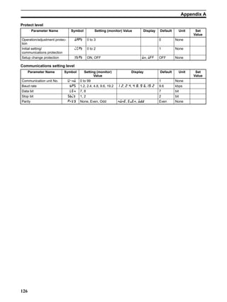
Download to read offline


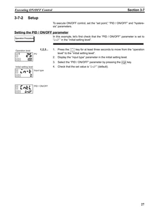
![41
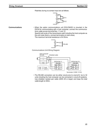
Shifting Input Values Section 4-1
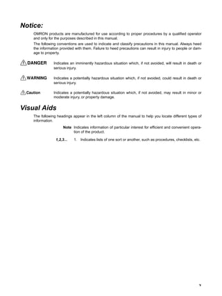
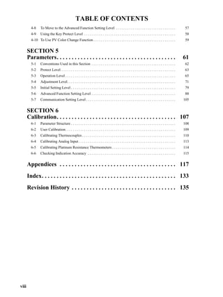
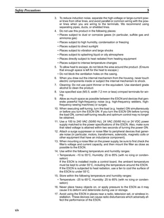
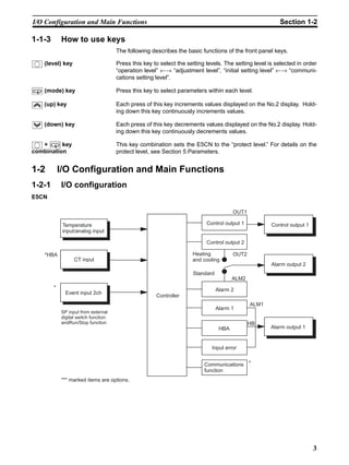
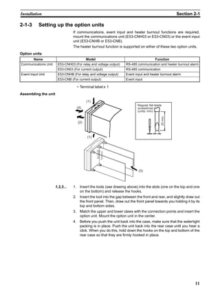
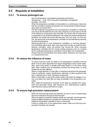
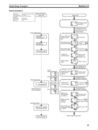
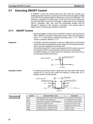
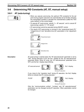
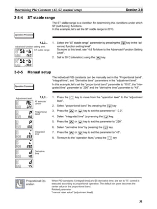
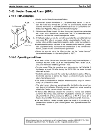
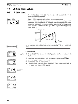
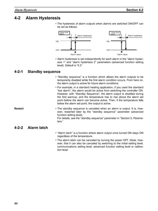
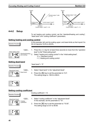
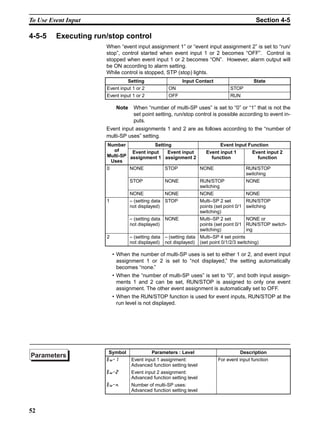
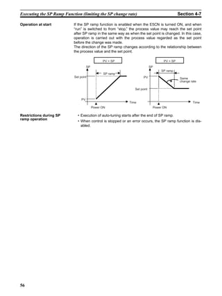
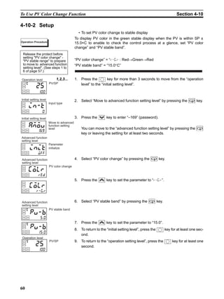
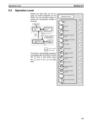
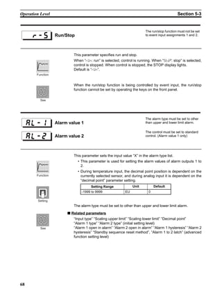
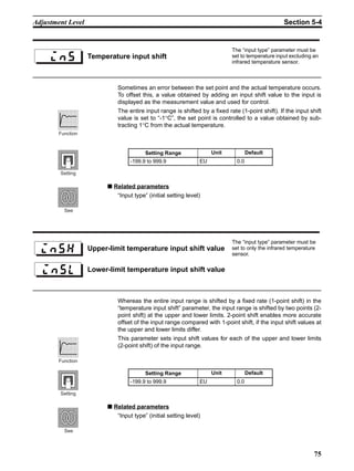
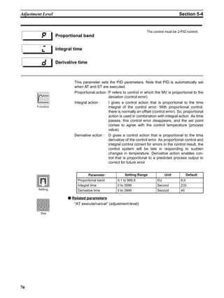
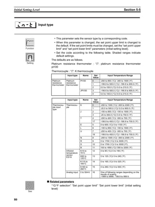
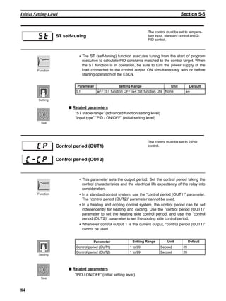
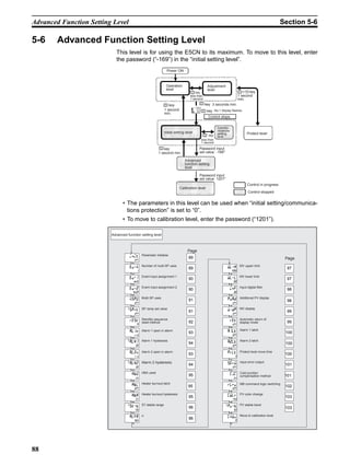
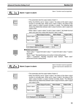
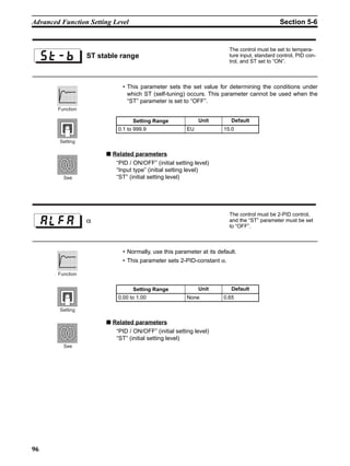
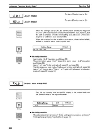
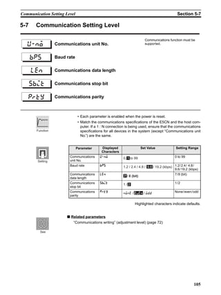
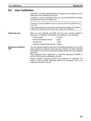
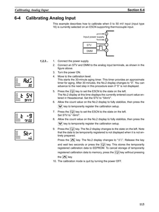
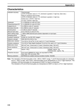
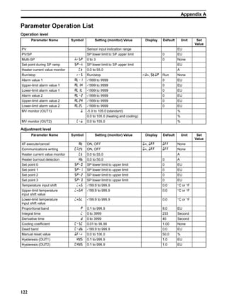
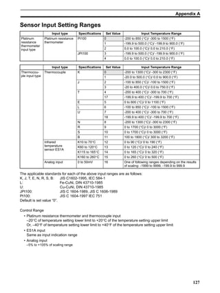
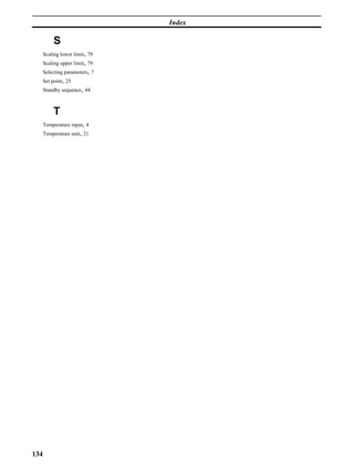
2-point shift • The input temperature range of infrared temperature sensors can be
shifted by setting an individual value for the upper and lower points of the
sensor range. This means that the shift can be applied equally across the
range with separate values for each end of the range. For example, if the
upper-limit value is set to “2°C” and the lower-limit value is set to “1°C”,
the sensor range is shifted by an average of 1.5°C at 50% input.
• Set the upper-limit value in the “upper-limit temperature input shift value”
parameter and the lower-limit value in the “lower-limit temperature input
shift value” parameter.
4-1-2 How to calculate input shift values (2-point shift)
When the infrared temperature sensor model ES1A is connected to the
E5CN, an offset of several to several tens of a degree can occur.
For this reason, offset the readout value by 1-point or 2-point shift as
described in this item. This offset occurs as a bias current for detecting con-
troller sensor error flows to the output impedance of the infrared temperature
sensor. 2-point shift can be carried out only on infrared temperature sensors,
and cannot be set for other input types.
[Preparations]
1,2,3... 1. Set to the temperature range matching the input specifications of the infra-
red temperature sensor. (ES1A is supported only in thermocouple input
types on the E5CN.)
2. Prepare a thermometer capable of measuring the temperature of the con-
trol target as shown in Figure 1 so that 1-point shift or 2-point shift can be
carried out.
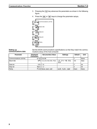
Upper-limit
temperature
input shift
value
Lower-limit
temperature
input shift
value
Input
Temperature
Upper-limit
value
Lower-limit value
Upper-limit temperature input shift value
After shift
Before shift
Lower-limit temperature
input shift value 100
0
Figure 1 Configuration When Compensating an Infrared Temperature Sensor
Infrared
temperature
sensor
(A) E5CN
(B) Thermometer
(C) Control target](https://image.slidesharecdn.com/omrome5cni-160407162259/85/controlador-manual-54-320.jpg)


![133
Index
Symbols
[down] key, 3
[level] + [mode] key combination, 3
[mode] key, 3
Numerics
1-point shift method, 42
2-PID control, 26
3-position control, 26
A
Adjustment level, 6
Advanced function setting level, 6
Alarm 1 type, 69, 92
Alarm 2 type, 92
Alarm latch, 44
Alarm output/Control output 2, 14
Analog input, 4
Analog input (voltage input), 46
AT execute/cancel, 28
C
Calibration level, 6
Changing the SP, 25
Communications data length, 105
Communications parity, 105
Communications setting level, 6
Communications stop bit, 105
Communications unit No., 105
Control output, 4
D
Decimal point, 66, 68, 69, 79, 91
Derivative time, 28, 31, 72
Display, 2
E
Event input, 66
Example of 2-point temperature input shift, 43
F
Fixing settings, 7
H
HBA, 4
Heater burnout detection, 36, 73
Hysteresis, 26
I
I/O configuration, 3
Initial setting level, 6
Initial/communications protection, 79
Input sensor types, 4
Input type, 81, 127
Integral time, 28
M
Manual setup, 31
N
Number of multi-SP uses, 49
O
ON/OFF control, 27
Operation indicators, 2
Operation level, 6, 25, 27, 71, 79
P
PID constants, 28
precautions, xi
Precautions when wiring, 13
Proportional band, 28, 72
PV/SP, 25, 67
R
Registering calibration data, 109](https://image.slidesharecdn.com/omrome5cni-160407162259/85/controlador-manual-146-320.jpg)


This 3-page document is a user's manual for an E5CN Temperature Controller. It begins with precautionary notices for safe operation and use of the device. The manual then provides: 1. An overview of the controller's features and basic functions, including names of parts, I/O configuration, setup levels, and communications functions. 2. Instructions for installation, wiring terminals, and requests at installation. 3. Guidelines for basic operation, such as initial setup examples, setting the input type and PID control mode, alarms, and determining PID constants. 4. Details for more advanced applications, including shifting input values, alarm hysteresis, scaling, heating/cooling control, and


