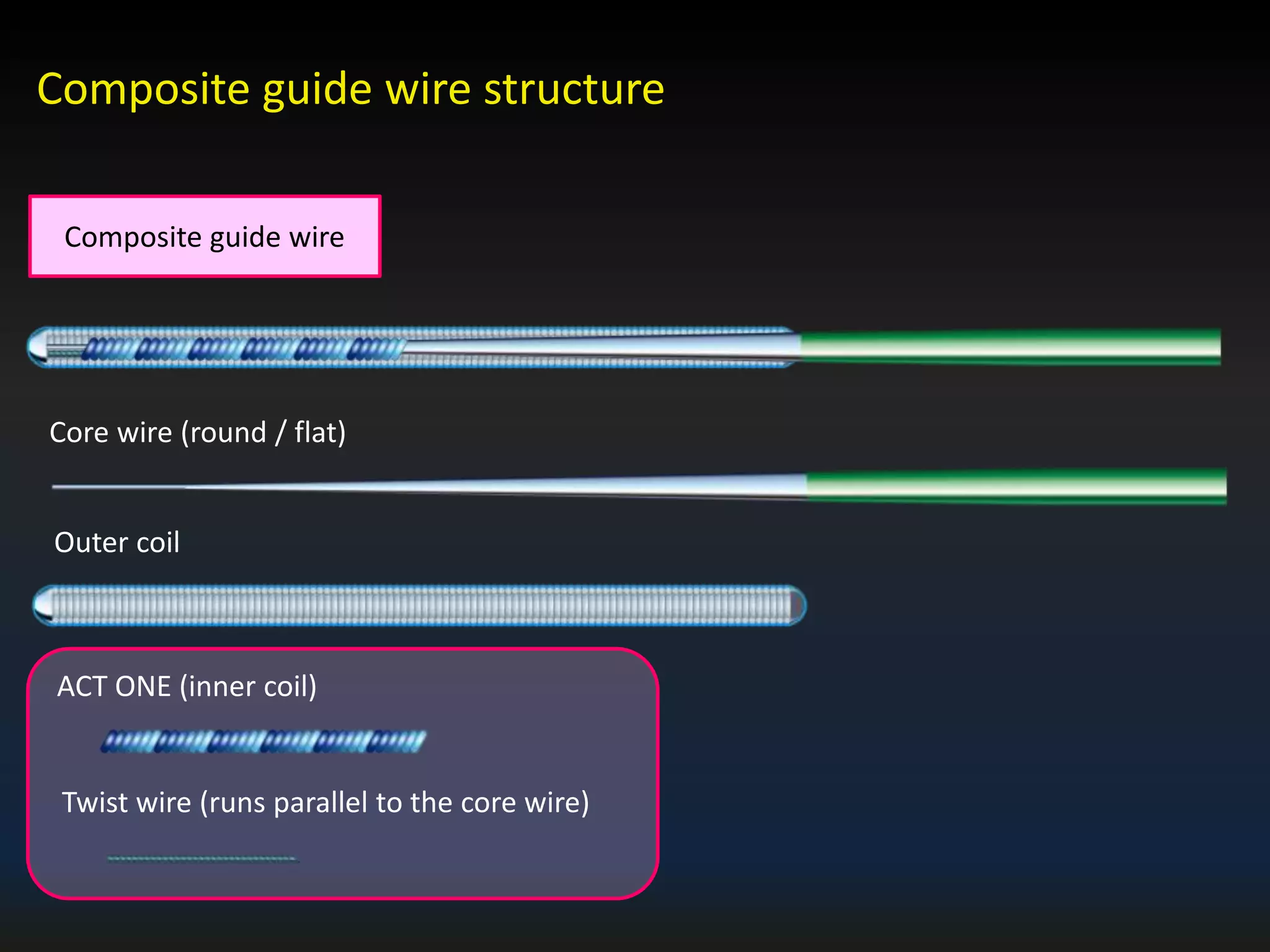
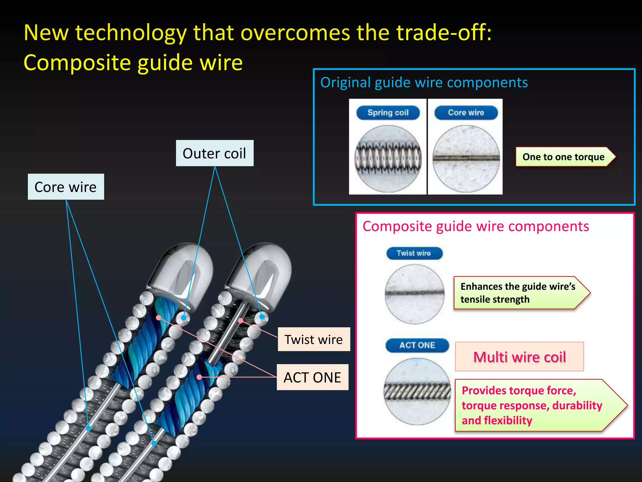
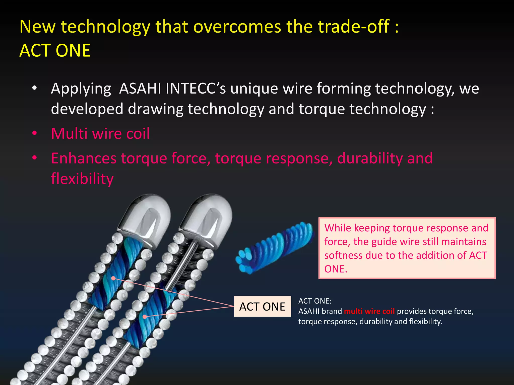
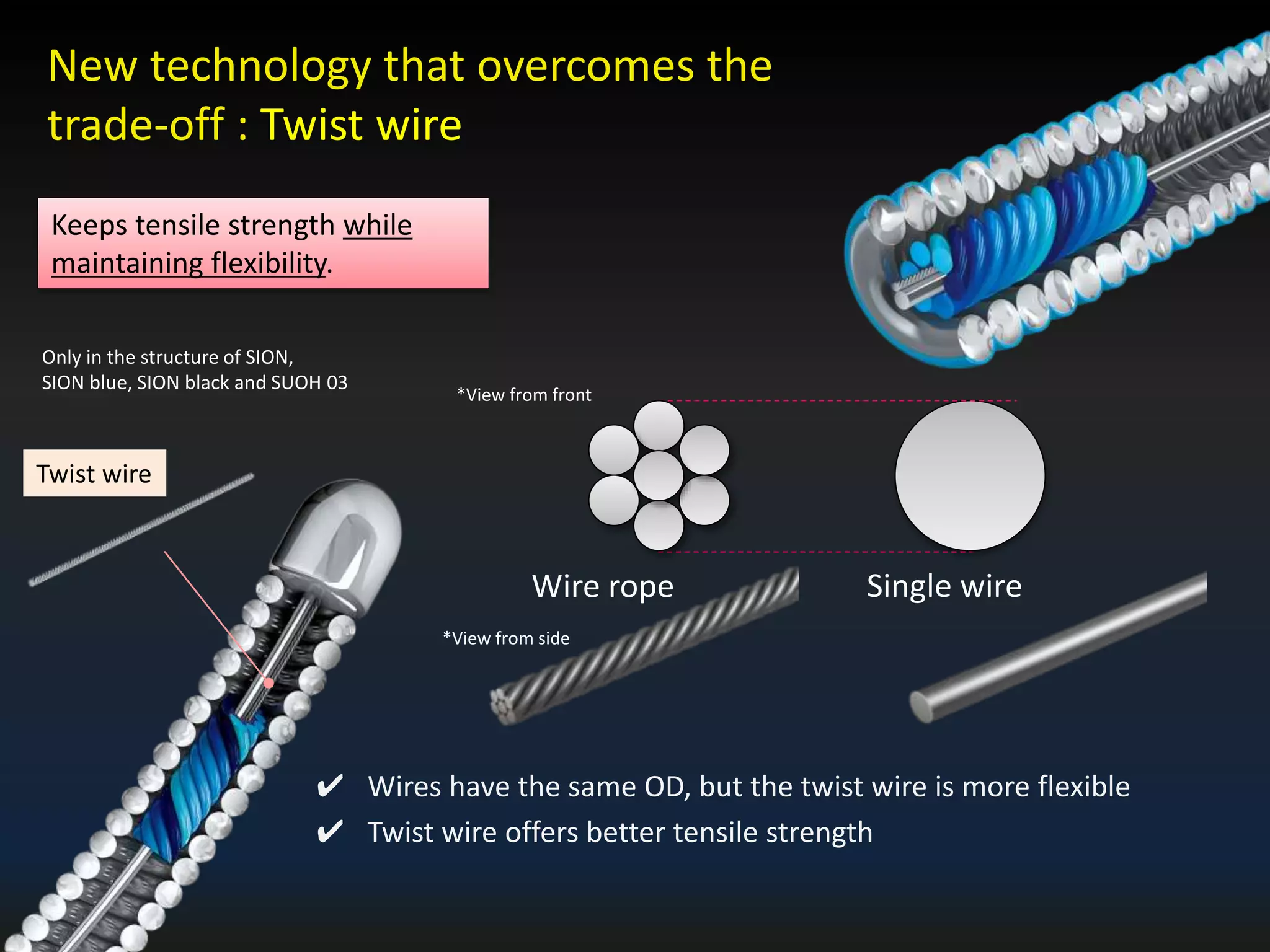
The document discusses the fundamental understanding of guide wires and their selection for CTO (Chronic Total Occlusion) procedures, emphasizing the importance of wire structure and performance attributes. It introduces Asahi's composite guide wire technology, detailing components like outer coils, core wires, and innovations like the 'Act One' inner coil to enhance torque response, durability, and flexibility. The analysis includes various case studies and comparisons of penetration efficacy, torque force, and lubrication efficiency among different guide wire designs.


![Relation of tip load and penetration force
73
0 100 200 300 400 500 600 700 800 900 1000
Gaia Next 3
Gaia 3rd
Conquest Pro
Miracle 12
Conquest Pro 8-20
Conqeust Pro 12
Penetration force [gf/mm2]
0 5 10 15 20 25
Gaia Next 3
Gaia 3rd
Conquest Pro
Miracle 12
Conquest Pro 8-20
Conqeust Pro 12
Tip load](https://image.slidesharecdn.com/wireselectioneuroctoclub2018-180919091044/75/CTO-fundamental-Understanding-of-Wire-Structure-65-2048.jpg)
![0.0
200.0
400.0
2 5 10 15 20 25 30
Gaia Third Gaia next 3rd
Conquest Pro Conquest Pro12
Conquest Pro8-20 Miracle 12
74
Stiff
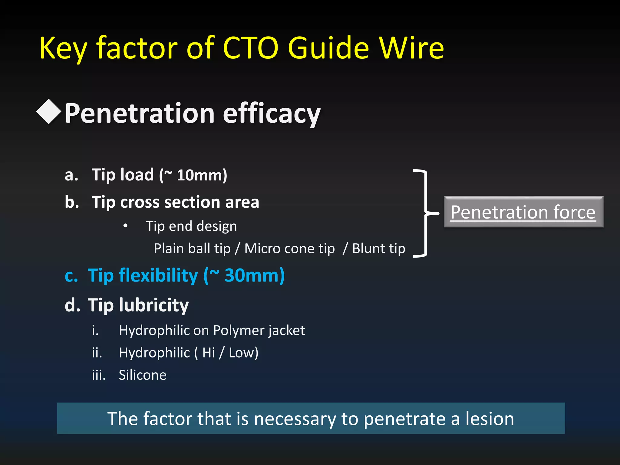
- Tip flexibility
[mm]
Guide wire
[mN]](https://image.slidesharecdn.com/wireselectioneuroctoclub2018-180919091044/75/CTO-fundamental-Understanding-of-Wire-Structure-66-2048.jpg)


