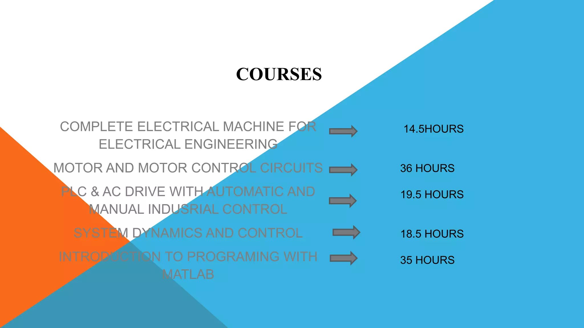
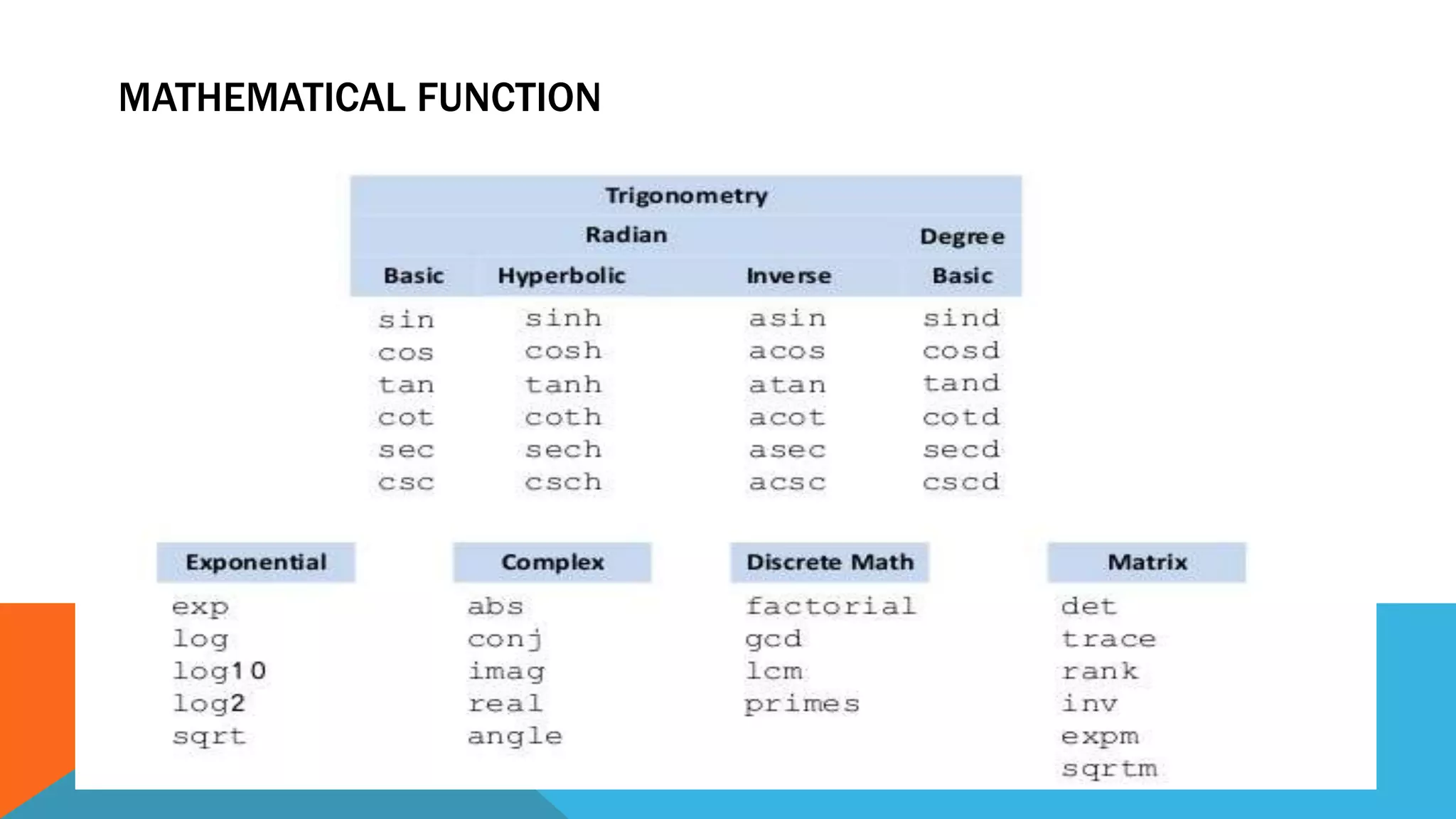
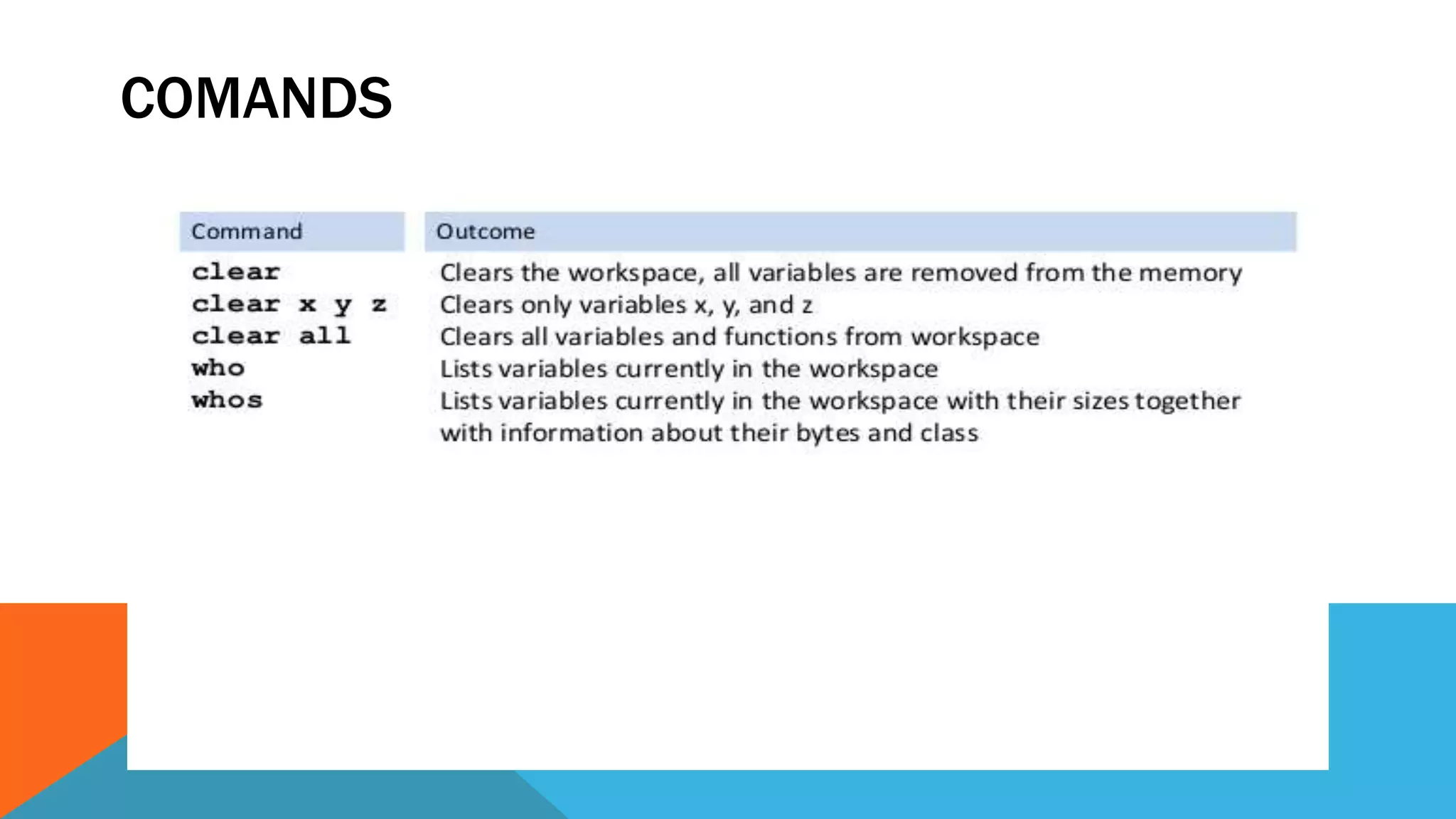
POORNIMA COLLEGE OF ENGINEERING,JAIPUR
SUBMITTED TO :- SUBMITTED BY :-
MR.MAHESH MEENA SHUBHAM DADHICH
TRAINING CORDINATOR PCE18EE704
Industrial Training Presentation,2020
INDEX
 INTRODUCTION
 COURSES
 COMPANY PROFILE
 COMPLETE ELECTRICAL MACHINE FOR ELECTRICAL ENGINEERING
 MOTOR AND MOTOR CONTROL CIRCUITS
 PLC & AC DRIVE WITH AUTOMATIC AND MANUAL INDUSTRIAL CONTROL
 SYSTEM DYNAMICS AND CONTROL
 INTRODUCTION TO PROGRAMING WITH MATLAB
COMPLETE ELECTRICAL MACHINE FOR
ELECTRICAL ENGINEERING
MOTOR AND MOTOR CONTROL CIRCUITS
PLC & AC DRIVE WITH AUTOMATIC AND
MANUAL INDUSRIAL CONTROL
SYSTEM DYNAMICS AND CONTROL
INTRODUCTION TO PROGRAMING WITH
MATLAB
14.5HOURS
36 HOURS
19.5 HOURS
18.5 HOURS
35 HOURS
COURSES
• Coursera was founded by Daphne Koller and Andrew Ng with a vision of
providing life-transforming learning experiences to anyone, anywhere.
• More than 200 of the world’s top universities and industry educators
partner with Coursera to offer courses, Specializations, certificates, and
degree programs
• Coursera courses last approximately four to ten weeks, with one to two
hours of video lectures a week.
• These courses provide quizzes, weekly exercises, peer-graded
assignments, an optional Honors assignment and sometimes a final
project or exam.
COMPANY PROFILE
• As of 2017 Coursera offers full master's degrees. They first started with
Master's in Innovation and Entrepreneurship (OMIE)
• Coursera is backed by leading investors that include Kleiner Perkins, New
Enterprise Associates, Learn Capital, and SEEK Group
• 2,400 companies trust the company’s enterprise platform Coursera for
Business to transform their talent.
• Coursera for Campus empowers any university to offer high-quality, job-
relevant online education to students, alumni, faculty, and staff
COMPLETE ELECTRICAL MACHINE
FOR
ELECTRICAL ENGINEERING
TYPES OF MACHINE
DC Machine consists:-
1. Separately excited DC Motor/ Generator
2. DC Series Motor/ Generator
3. DC Shunt Motor / Generator
4. Compound motor / Generator
Induction Machine Consists:-
1. Single Phase Induction Motor/ Generator
2. Three Phase Induction Motor/ Generator
Synchronous Machine Consists:-
1. Rotating Armature Type
2. Rotating Field Type
PRINCIPLE OF OPERATION OF SYNCHRONOUS
GENERATOR
 The synchronous generator works on the principle of Faraday
laws of electromagnetic induction.
 In order to generate electricity in the three phase winding, we need variation of flux or variation in
number of turns.
 So we use the rotation of DC flux in air gap as a varying field.
 Rotation of DC flux appears as varying field to the 3 phase stationary winding.
 EMF will also be generated due the relative motion between
the conductor and the field induces the EMF in the conductor.
 EMF will be shifted by 120 degree due to displacement by 120 degree in space between windings.
STARTING OF INDUCTION MOTOR
Why starting current is high?
• Because at starting, slip=1, so impedance would be minimum so starting current would be high.
• We need to reduce starting current and increase starting torque.
Importance of Induction Machines:-
• Wound rotor motors are suitable for loads requiring high starting torque and where a lower starting current
is required.
• Induction motors are used for the loads that require speed control.
• Induction motors are used in cranes, pumps, elevators and compressors.
• Induction generator requires less maintenance because of its robust construction.
• Cage motor is used as an induction generator as it is cheaper in
comparison.
• Induction generator does not require synchronization as synchronous motor.
• Induction generator is used in wind farms to generate electricity.
MOTOR AND MOTOR CONTROL CIRCUITS
Jay Mendelson is an instructor at University of Colorado Boulder, where he specializes in
online content development for sensor and motor technology. Prior to joining the faculty, Jay
had three VP level technology positions at Cooper Wiring Devices, Brooks Instrument, and
Omega Engineering. Jay is an industry expert in the design of transmitters, process
controllers, pressure, thermal and flow sensors, valves, and electrical switches and
connectors. He holds Bachelors (Princeton University) and Masters (Carnegie Mellon
University) degrees in Mechanical Engineering. Jay has authored 3 US utility patents and
21 design patent
Jay Mendelson
Instructor
University of Colorado Boulder
TRAINING INSTRUCTOR
PROFILE
WORKING PRINCIPLE
An electric motor is an electrical machine which converts electrical energy
into mechanical energy. The basic working principle of a DC motor is:
"whenever a current carrying conductor is placed in a magnetic field, it
experiences a mechanical force
WORKING PRINCIPLE OF AC MOTOR
An AC motor works by applying alternating current to stator windings, which
produce a rotating magnetic field. Because the magnetic field rotates in this way,
an AC motor does not need power or mechanical aid to be applied to the rotor
FIG. AC MOTOR CONSTRUCTION
SPEED CONTROL OF AC
MOTOR
ROTOR RHEOSTAT
CONTROL
CASCADE OPERATION
Entities that use
relationships often have
dependencies on the
existence of the other
entity in the relationship
With the
same rheostat added to
the rotor circuit, it is
possible to regulate the
speed of slip ring motors
WORKING PRINCIPLE OF DC MOTOR
The DC motor is the device which converts the direct current into the
mechanical work. It works on the principle of Lorentz Law, which states that
“the current-carrying conductor placed in a magnetic and
electric field experience a force”. The experienced force is called the Lorentz
force
SPEED CONTROL OF DC
MOTOR
FLUX CONTROL
METHOD
• This can be achieved by using
a variable resistor in a series
with the field winding resistor.
• Initially, when the variable
resistor is kept at its minimum
position, the rated current flows
through the field winding due to
a rated supply voltage, and as
a result, the speed is kept
normaL
ARMATURE CONTROL
METHOD
• One way is by
implementing armature resistance, which
involves connecting a variable resistance in
series to the circuit of the armature.
• Once resistance has been increased, the
current flow through the circuit is reduced
and the armature voltage drop is less than
the line voltage.
PLC & AC DRIVE WITH AUTOMATIC
AND MANUAL INDUSTRIAL CONTROL
PLC FOR AUTOMATION CONTROL
* The programming device is used to insert the program in memory
of the processor. The personal computer is the device used to
elaborate the logics, usually in ladder, and can be transferred to
the PLC via link or ethernet. The program is a series of
commands developed according to the needs of the user.
* Learning different language for programing plc like
LADDER,FBD and STL.
LANGUAGES IN PLC
1.Ladder - Ladder logic is used to develop software for programmable
logic controllers (PLCs) used in industrial control applications. The
name is based on the observation that programs in this language
resemble ladders, with two vertical rails and a series of horizontal rungs
between them.
2.FBD -The Function Block Diagram (FBD) is a graphical language for
programmable logic controller design, that can describe the function
between input variables and output variables.
3.STL - The Statement List (STL) programming language is one of the
three programming languages available in the basic STEP 7 software
package. It is a text-based programming language with a structure
similar to assembly language or machine code. STL is the
native language of S7-300 and S7-400 processors.
TYPE OF SENSOR
DEFINATION :
1.ACTIVE SENSOR -A Thermocouple is an Active Sensor as it
does not require any external power supply to operate.
2. PASSIVE SENSOR -A Passive Sensor requires an external
source of power to operate while an Active Sensor does not.
SYSTEM DYNAMICS AND CONTROL
INTRODUCTION :
• System dynamics is a highly abstract method of modeling. It
ignores the fine details of a system, such as the individual
properties of people, products, or events, and produces a general
representation of a complex system. Abstract simulation models
may be used for long-term, strategic modeling and simulation..
• The Dynamics and Control Group addresses research problems
relating to modelling, simulation and control of civil, mechanical
and aerospace engineering systems.
LAPLACE TRANSFORM
MODELING ELECTRICAL SYSTEM
INTRODUCTION WITH MATLAB
PROGRAMING
Akos Ledeczi, Ph.D.
Professor of Computer Engineering, Computer
Science and Electrical Engineering
Vanderbilt University
TRAINING INSTRUCTOR
PROFILE
Matrix and Operators:-
• Higher dimensions are uncommon
• The most common have special names:
• 2D array = “matrix” (plural is “matrices”)
• 1D array = “vector”
• Most ingenious part of Cleve Moler’s invention of MATLAB was the way he set
it up to deal with matrices.
• MATLAB stands for “Matrix Laboratory”!
• Matrix Multiplication:-
• Different from Array Multiplication!
• Z = X * Y means that for all valid m and n
• Inner dimensions of X and Y must be the same.
BASIC DATA VARIABLE
MATHEMATICAL FUNCTION
COMANDS
Online certification course matlab , electrical machine , motor and motor control ckt ppt

Online certification course matlab , electrical machine , motor and motor control ckt ppt

  • 1.
    POORNIMA COLLEGE OFENGINEERING,JAIPUR SUBMITTED TO :- SUBMITTED BY :- MR.MAHESH MEENA SHUBHAM DADHICH TRAINING CORDINATOR PCE18EE704 Industrial Training Presentation,2020
  • 2.
    INDEX  INTRODUCTION  COURSES COMPANY PROFILE  COMPLETE ELECTRICAL MACHINE FOR ELECTRICAL ENGINEERING  MOTOR AND MOTOR CONTROL CIRCUITS  PLC & AC DRIVE WITH AUTOMATIC AND MANUAL INDUSTRIAL CONTROL  SYSTEM DYNAMICS AND CONTROL  INTRODUCTION TO PROGRAMING WITH MATLAB
  • 3.
    COMPLETE ELECTRICAL MACHINEFOR ELECTRICAL ENGINEERING MOTOR AND MOTOR CONTROL CIRCUITS PLC & AC DRIVE WITH AUTOMATIC AND MANUAL INDUSRIAL CONTROL SYSTEM DYNAMICS AND CONTROL INTRODUCTION TO PROGRAMING WITH MATLAB 14.5HOURS 36 HOURS 19.5 HOURS 18.5 HOURS 35 HOURS COURSES
  • 4.
    • Coursera wasfounded by Daphne Koller and Andrew Ng with a vision of providing life-transforming learning experiences to anyone, anywhere. • More than 200 of the world’s top universities and industry educators partner with Coursera to offer courses, Specializations, certificates, and degree programs • Coursera courses last approximately four to ten weeks, with one to two hours of video lectures a week. • These courses provide quizzes, weekly exercises, peer-graded assignments, an optional Honors assignment and sometimes a final project or exam. COMPANY PROFILE
  • 5.
    • As of2017 Coursera offers full master's degrees. They first started with Master's in Innovation and Entrepreneurship (OMIE) • Coursera is backed by leading investors that include Kleiner Perkins, New Enterprise Associates, Learn Capital, and SEEK Group • 2,400 companies trust the company’s enterprise platform Coursera for Business to transform their talent. • Coursera for Campus empowers any university to offer high-quality, job- relevant online education to students, alumni, faculty, and staff
  • 6.
  • 7.
    TYPES OF MACHINE DCMachine consists:- 1. Separately excited DC Motor/ Generator 2. DC Series Motor/ Generator 3. DC Shunt Motor / Generator 4. Compound motor / Generator Induction Machine Consists:- 1. Single Phase Induction Motor/ Generator 2. Three Phase Induction Motor/ Generator Synchronous Machine Consists:- 1. Rotating Armature Type 2. Rotating Field Type
  • 8.
    PRINCIPLE OF OPERATIONOF SYNCHRONOUS GENERATOR  The synchronous generator works on the principle of Faraday laws of electromagnetic induction.  In order to generate electricity in the three phase winding, we need variation of flux or variation in number of turns.  So we use the rotation of DC flux in air gap as a varying field.  Rotation of DC flux appears as varying field to the 3 phase stationary winding.  EMF will also be generated due the relative motion between the conductor and the field induces the EMF in the conductor.  EMF will be shifted by 120 degree due to displacement by 120 degree in space between windings.
  • 9.
    STARTING OF INDUCTIONMOTOR Why starting current is high? • Because at starting, slip=1, so impedance would be minimum so starting current would be high. • We need to reduce starting current and increase starting torque. Importance of Induction Machines:- • Wound rotor motors are suitable for loads requiring high starting torque and where a lower starting current is required. • Induction motors are used for the loads that require speed control. • Induction motors are used in cranes, pumps, elevators and compressors. • Induction generator requires less maintenance because of its robust construction. • Cage motor is used as an induction generator as it is cheaper in comparison. • Induction generator does not require synchronization as synchronous motor. • Induction generator is used in wind farms to generate electricity.
  • 10.
    MOTOR AND MOTORCONTROL CIRCUITS
  • 11.
    Jay Mendelson isan instructor at University of Colorado Boulder, where he specializes in online content development for sensor and motor technology. Prior to joining the faculty, Jay had three VP level technology positions at Cooper Wiring Devices, Brooks Instrument, and Omega Engineering. Jay is an industry expert in the design of transmitters, process controllers, pressure, thermal and flow sensors, valves, and electrical switches and connectors. He holds Bachelors (Princeton University) and Masters (Carnegie Mellon University) degrees in Mechanical Engineering. Jay has authored 3 US utility patents and 21 design patent Jay Mendelson Instructor University of Colorado Boulder TRAINING INSTRUCTOR PROFILE
  • 12.
    WORKING PRINCIPLE An electricmotor is an electrical machine which converts electrical energy into mechanical energy. The basic working principle of a DC motor is: "whenever a current carrying conductor is placed in a magnetic field, it experiences a mechanical force
  • 13.
    WORKING PRINCIPLE OFAC MOTOR An AC motor works by applying alternating current to stator windings, which produce a rotating magnetic field. Because the magnetic field rotates in this way, an AC motor does not need power or mechanical aid to be applied to the rotor FIG. AC MOTOR CONSTRUCTION
  • 14.
    SPEED CONTROL OFAC MOTOR ROTOR RHEOSTAT CONTROL CASCADE OPERATION Entities that use relationships often have dependencies on the existence of the other entity in the relationship With the same rheostat added to the rotor circuit, it is possible to regulate the speed of slip ring motors
  • 15.
    WORKING PRINCIPLE OFDC MOTOR The DC motor is the device which converts the direct current into the mechanical work. It works on the principle of Lorentz Law, which states that “the current-carrying conductor placed in a magnetic and electric field experience a force”. The experienced force is called the Lorentz force
  • 16.
    SPEED CONTROL OFDC MOTOR FLUX CONTROL METHOD • This can be achieved by using a variable resistor in a series with the field winding resistor. • Initially, when the variable resistor is kept at its minimum position, the rated current flows through the field winding due to a rated supply voltage, and as a result, the speed is kept normaL ARMATURE CONTROL METHOD • One way is by implementing armature resistance, which involves connecting a variable resistance in series to the circuit of the armature. • Once resistance has been increased, the current flow through the circuit is reduced and the armature voltage drop is less than the line voltage.
  • 17.
    PLC & ACDRIVE WITH AUTOMATIC AND MANUAL INDUSTRIAL CONTROL
  • 18.
    PLC FOR AUTOMATIONCONTROL * The programming device is used to insert the program in memory of the processor. The personal computer is the device used to elaborate the logics, usually in ladder, and can be transferred to the PLC via link or ethernet. The program is a series of commands developed according to the needs of the user. * Learning different language for programing plc like LADDER,FBD and STL.
  • 19.
    LANGUAGES IN PLC 1.Ladder- Ladder logic is used to develop software for programmable logic controllers (PLCs) used in industrial control applications. The name is based on the observation that programs in this language resemble ladders, with two vertical rails and a series of horizontal rungs between them. 2.FBD -The Function Block Diagram (FBD) is a graphical language for programmable logic controller design, that can describe the function between input variables and output variables. 3.STL - The Statement List (STL) programming language is one of the three programming languages available in the basic STEP 7 software package. It is a text-based programming language with a structure similar to assembly language or machine code. STL is the native language of S7-300 and S7-400 processors.
  • 20.
  • 21.
    DEFINATION : 1.ACTIVE SENSOR-A Thermocouple is an Active Sensor as it does not require any external power supply to operate. 2. PASSIVE SENSOR -A Passive Sensor requires an external source of power to operate while an Active Sensor does not.
  • 22.
  • 23.
    INTRODUCTION : • Systemdynamics is a highly abstract method of modeling. It ignores the fine details of a system, such as the individual properties of people, products, or events, and produces a general representation of a complex system. Abstract simulation models may be used for long-term, strategic modeling and simulation.. • The Dynamics and Control Group addresses research problems relating to modelling, simulation and control of civil, mechanical and aerospace engineering systems.
  • 24.
  • 25.
  • 26.
  • 27.
    Akos Ledeczi, Ph.D. Professorof Computer Engineering, Computer Science and Electrical Engineering Vanderbilt University TRAINING INSTRUCTOR PROFILE
  • 28.
    Matrix and Operators:- •Higher dimensions are uncommon • The most common have special names: • 2D array = “matrix” (plural is “matrices”) • 1D array = “vector” • Most ingenious part of Cleve Moler’s invention of MATLAB was the way he set it up to deal with matrices. • MATLAB stands for “Matrix Laboratory”! • Matrix Multiplication:- • Different from Array Multiplication! • Z = X * Y means that for all valid m and n • Inner dimensions of X and Y must be the same.
  • 29.
  • 30.
  • 31.