Download to read offline
![International Research Journal of Engineering and Technology (IRJET) e-ISSN: 2395-0056
Volume: 04 Issue: 08 | Aug -2017 www.irjet.net p-ISSN: 2395-0072
© 2017, IRJET | Impact Factor value: 5.181 | ISO 9001:2008 Certified Journal | Page 2082
Fig – 24: FEM results of all connections
The graphs are plotted against moment v/s rotation
based on the results obtained for each connection. The
failure of a connection in FEM analysis is considered
when the stress reaches the yield strength of the section,
the yield strength of the section used is 550 N/mm2.
The failure of connections in FEM analysis is due to the
buckling of the beam at the point of application of
load.The failure of connection C3 and C4 is at a higher
load as compared to that of connections C1 and C2, this
is due to the presence of angle plate.
5. CONCLUSION
1. Connection C1 and C2 have more rotation at less
amount of load than the connections C3 and C4,
therefore it is not recommended.
2. The failure of connection in FEM analysis is due
to the torsional buckling of the beam at the
point of load applied.
3. The failure of the connection C3 and C4 is due to
the distortion of angle plates as well as
distortion of beam-column connector.
4. The connections C3 and C4 have high ultimate
moment capacity than connections C1 and C2.
6. REFERENCE
[1]British standards institution. 1998. BS 5950:
structural use o steel works in buildings: part 5: code of
practice for the design of cold formed sections: London
UK.
[2]Alireza Bagheri Sabbagha, Mihail Petkovski et al
[3]Kypros Pilakoutas , Rasoul Mirghaderi et al
[4]K.F. Chung and K.H. Ip
[5]Bhavitha E B, Rosemol K George and Teena Joy
[6]Bayan Anwer Ali, Sariffuddin Saad and Mohd Hanim
Osman “Cold-formed steel joints and structures- A
review” International Journal of Civil and Structural
Engineering Volume 2, No.2,2011.
[7]M.F. Wong and K.F. Chung “Experimental
investigation of cold-formed steel beam-column sub-
frames: enhanced performance” Structural Engineering,
Mechanics and Computation (Vol. 2), 2001
0.0 0.1 0.2 0.3 0.4 0.5 0.6 0.7 0.8 0.9 1.0 1.1 1.2 1.3
0.00
0.02
0.04
0.06
0.08
0.10
0.12
0.14
0.16
0.18
0.20 FEM Results
Moment(kN-m)
Rotations (Rad)
C1
C2
C3
C4](https://image.slidesharecdn.com/irjet-v4i8375-170926091029/75/Analysis-of-Cold-Formed-Steel-Connections-using-FEM-7-2048.jpg)

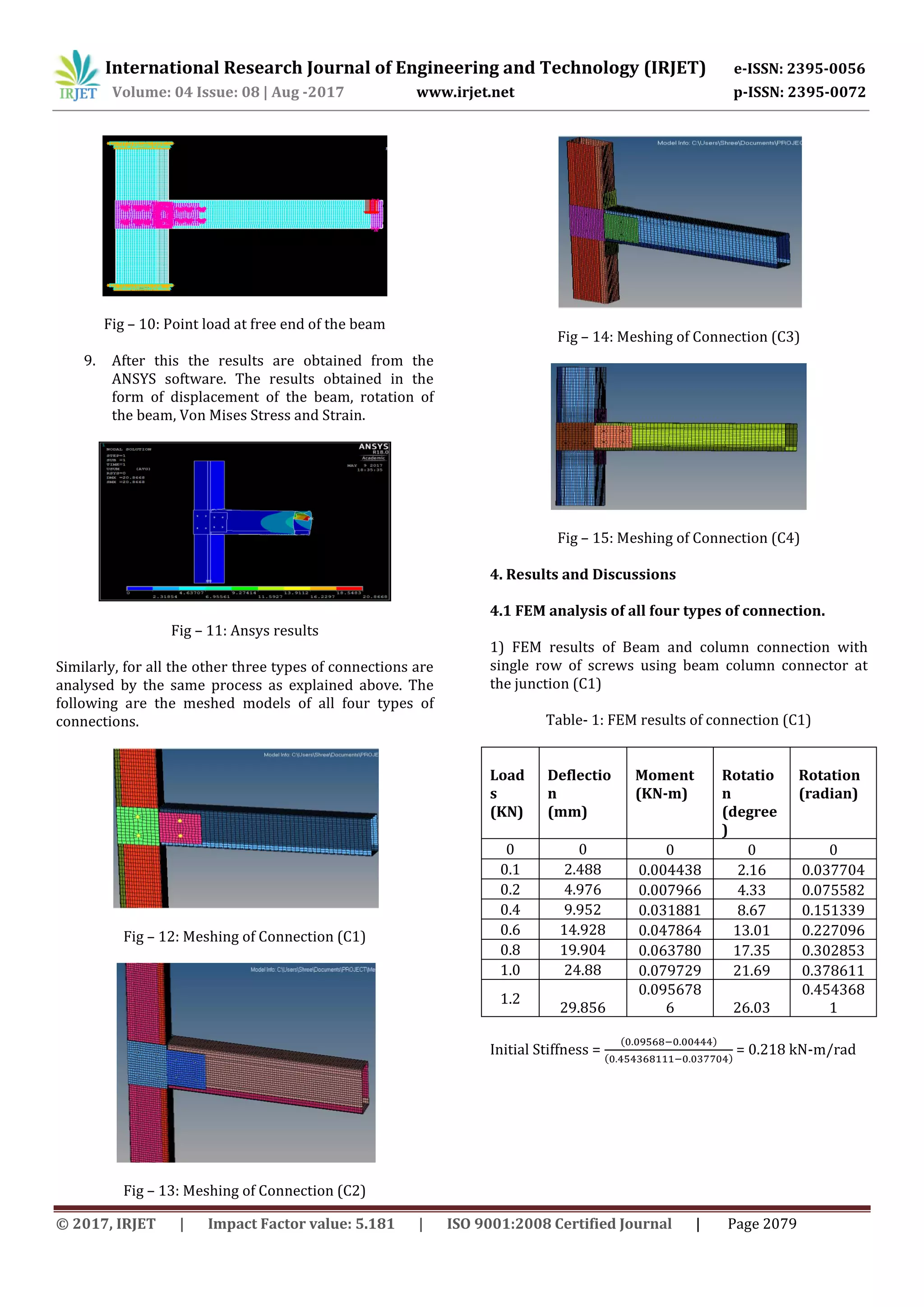
1. The document analyzes cold formed steel connections using finite element modeling (FEM). Four different beam-column connection configurations are modeled and tested, including connections with single or double rows of screws with or without angle plates. 2. Experimental results for each connection are compared to FEM analysis results from ANSYS. The connections are modeled in CATIA and meshed in Hypermesh before analysis in ANSYS to determine load-carrying capacity, displacement, stress, and strain. 3. Preliminary results show that connections using double rows of screws and angle plates have higher load capacities than those with single rows or without plates. Further comparison of experimental and FEM results will provide insight into optimizing cold formed steel