![1 Introduction
1.1 Augmented Reality
Augmented reality (AR) is the integration of digital information with a live video of user’s
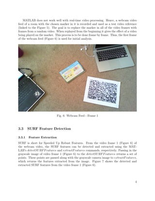
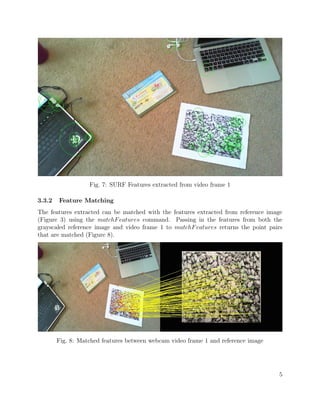
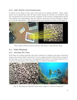
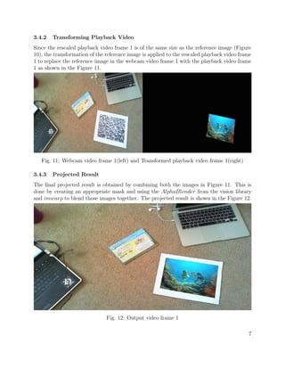
environment in real time. Its interfaces consist of a blend of both real and virtual content.
It presents the user a virtual way to interact with the environment. It is an evolving field of
research in computer vision and widely used in interactive gaming platforms and in various
sports to display scores and statistics on the playing field.
1.2 Objective
The goal of this project is to create an augmented reality video playlist that presents the
user an environment to interact with a playlist of videos.
The aim of the first part of the project is to play a set of videos on everyday objects that
are found in the living room using a live webcam feed. The choice of markers is crucial for
the process. SURF feature extraction algorithm is used for the object recognition and pose
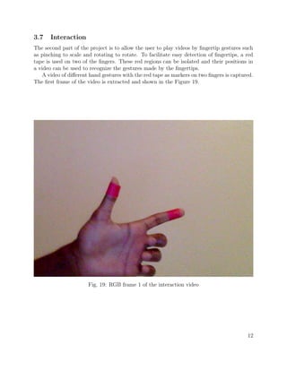
estimation. The aim of the second part of the project is to add interaction, allowing the user
to select a particular video and view it as desired using finger gestures. The fingertips of the
user are detected by the help of a set of markers and the 2D transformation is calculated to
play the video as desired by the user.
Assumptions: This project is implemented in a MATLAB environment and uses a webcam
recorded video instead of a live feed to implement the algorithm.
2 Previous Work
The SURF feature detection[1] is a popular method for object recognition. The detector
and descriptor schemes used in SURF feature detection can be applied for real-world object
recognition. It uses a repeatability score for the detectors that gives the number of interest
points found for the part of the image visible in both the test image and the scene image.
This detector-description scheme is found to out perform current state of the art, both in
speed and accuracy.
Tracking features that are extracted from successive frames of a video is the main part
of this project, where computationally efficient way to keep track of the features extracted
in each frame is required.In SURFTrac[2], instead of tracking in 2D images, it is useful
to search and match candidate features in local neighborhoods inside a 3D image pyramid
without computing their feature descriptors that are further validated by fitting to a motion
model. First, SURF features extracted from the first video frame image are matched against
the rest, followed by using RANSAC algorithm and finding the best image as key node.
Next, placement of labels is computed. At every new video frame, the SURFTrac[2] is run
to update the interest points, compute the homography against the previous video frame,
1](https://image.slidesharecdn.com/336acd91-17cf-4701-a7e9-9209ba0dcac6-151129060925-lva1-app6891/85/Augmented-Reality-Video-Playlist-Computer-Vision-Project-3-320.jpg)
![and update the label location accordingly. SURFTrac[2] algorithm is an efficient method for
tracking scale-invariant interest points without computing their descriptors.
Augmented Reality inspection of objects using markerless fingertip detection[3] is helpful
for the second part of this project, which involves playing videos using fingertip detection.
The skin tone or skin color is used to segment the hand from the background. After which,
ellipses are fitted at fingertips based on candidate curvature points according to the hand
contour. It takes 10 seconds to first detect the hand and fingers with fingers held up.
Fingertip trajectory is tracked by a matching algorithm that minimizes the displacement of
pairs of fingertips over two frames. Using a model of the hand created earlier, the pose of
the hand can be estimated. For the purpose of this project, instead of using the skin tone to
segment the entire hand, red tape is used as markers on the fingertips, which are segmented
out and their gestures are used to play the videos accordingly.
3 Algorithm
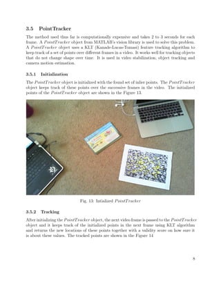
3.1 Selecting Markers
Fig. 1: Fiducial marker Fig. 2: Plain book cover
The shape of the marker should preferably be a rectangle to facilitate a proper video
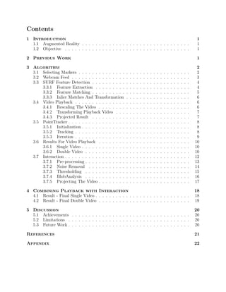
playing surface. Figure 3.1 shows a fiducial marker that is very good for detection, tracking
and pose estimation, but this is not an everyday item that is found in a living room and
hence, it is not used in this project. Figure 2 shows a plain notebook cover that is a common
everyday item found in a room. However, due to its lack of features, it is not suitable for
the SURF feature detection algorithm used in this project.
2](https://image.slidesharecdn.com/336acd91-17cf-4701-a7e9-9209ba0dcac6-151129060925-lva1-app6891/85/Augmented-Reality-Video-Playlist-Computer-Vision-Project-4-320.jpg)
![References
[1] Bay, Herbert, et al. Speeded-up robust features (SURF). Computer vision and image
understanding 110.3 (2008): 346-359.
[2] Ta, Duy-Nguyen, et al. Surftrac: Efficient tracking and continuous object recognition
using local feature descriptors. Computer Vision and Pattern Recognition, 2009. CVPR
2009. IEEE Conference on. IEEE, 2009.
[3] Lee, Taehee, and Tobias Hollerer. Handy AR: Markerless inspection of augmented reality
objects using fingertip tracking. Wearable Computers, 2007 11th IEEE International
Symposium on. IEEE, 2007.
21](https://image.slidesharecdn.com/336acd91-17cf-4701-a7e9-9209ba0dcac6-151129060925-lva1-app6891/85/Augmented-Reality-Video-Playlist-Computer-Vision-Project-23-320.jpg)
![Appendix
MATLAB Code:
clear all
close all
%% INITIALIZATION FOR FEATURES AND RED TRACKING
% webcamera or a video to use
camera = vision.VideoFileReader('refboth3.avi');
% videos to be played
video1 = vision.VideoFileReader('turtle.mp4');
video2 = vision.VideoFileReader('turtle.mp4');
% setup a video writer and video player to view the output
videoFWriter = vision.VideoFileWriter('Output_both4.avi', ...
'FrameRate', camera.info.VideoFrameRate);
camInfo = camera.info.VideoSize;
vid1Info = video1.info.VideoSize;
screenSize = get(0,'ScreenSize');
videoPlayer = vision.VideoPlayer('Name','OUTPUT','Position',...
[50 50 camInfo(1)+20 camInfo(2)+20]);
% Threshold for red detection
redThresh = 0.25;
%Extract blobs and Texts that need to be printed on the video
% Set blob analysis handling
hblob = vision.BlobAnalysis('AreaOutputPort', false, ...
'CentroidOutputPort', true, ...
'BoundingBoxOutputPort', true', ...
'MinimumBlobArea', 300, ...
'MaximumBlobArea', 5000, ...
'MaximumCount', 10);
% Set Red box handling
hshapeinsRedBox = vision.ShapeInserter('BorderColor', 'Custom', ...
'CustomBorderColor', [1 0 0], ...
'Fill', true, ...
'FillColor', 'Custom', ...
'CustomFillColor', [1 0 0], ...
'Opacity', 0.4);
% Set text for number of blobs
htextins = vision.TextInserter('Text', 'Number of Red Object: %2d', ...
'Location', [7 2], ...
'Color', [1 0 0], ... // red color
'FontSize', 12);
22](https://image.slidesharecdn.com/336acd91-17cf-4701-a7e9-9209ba0dcac6-151129060925-lva1-app6891/85/Augmented-Reality-Video-Playlist-Computer-Vision-Project-24-320.jpg)
![% set text for centroid
htextinsCent = vision.TextInserter('Text', '+ X:%4d, Y:%4d', ...
'LocationSource', 'Input port', ...
'Color', [1 1 0], ... // yellow color
'FontSize', 14);
% set text for centroid
htextinsCent2 = vision.TextInserter('Text', '+ X:%4d, Y:%4d', ...
'LocationSource', 'Input port', ...
'Color', [1 1 0], ... // yellow color
'FontSize', 14);
nFrame = 0; % Frame number initialization
%% forward the video to played/camera input video by frames as required
for k = 1:200
step(video1);
end
for k = 1:300
step(video2);
end
for k = 1:45
step(camera);
end
%% LOAD REF IMAGE AND FEATURES
%Reference images
refImg1 = imread('stones_edit.jpg');
refImg2 = imread('book.jpg');
refImgGray1 = rgb2gray(refImg1);
refPts1 = detectSURFFeatures(refImgGray1);
refFeatures1 = extractFeatures(refImgGray1,refPts1);
refImgGray2 = rgb2gray(refImg2);
refPts2 = detectSURFFeatures(refImgGray2);
refFeatures2 = extractFeatures(refImgGray2,refPts2);
Frame = 0;
start = 1;
looped = 0;
flag1 = 1;
23](https://image.slidesharecdn.com/336acd91-17cf-4701-a7e9-9209ba0dcac6-151129060925-lva1-app6891/85/Augmented-Reality-Video-Playlist-Computer-Vision-Project-25-320.jpg)
![flag2 = 1;
%% MAIN LOOP
while ~isDone(camera)
error1 = 0;
error2 = 0;
% red object
if(looped == 0)
camImg = step(camera);
videoFrame1 = step(video1);
videoFrame2 = step(video2);
end
looped = 0;
% obtain the mirror image for displaying incase of laptop built in cam
% rgbFrame = flipdim(rgbFrame,2);
% Get red component of the image
diffFrame = imsubtract(camImg(:,:,1), rgb2gray(camImg));
% Filter out the noise by using median filter
diffFrame = medfilt2(diffFrame, [3 3]);
% Convert the image into binary image with the red objects as white
binFrame = im2bw(diffFrame, redThresh);
% Get the centroids and bounding boxes of the blobs
[centroid, bbox] = step(hblob, binFrame);
% Convert the centroids into Integer for further steps
centroid = uint16(centroid);
%camImg(1:20,1:165,:) = 0; % put a black region on the output stream
if(length(bbox(:,1)) >= 2)
vidIn = step(hshapeinsRedBox, camImg, bbox); % Insert the red box
centerX = uint16(0);
centerY = uint16(0);
scaleX = uint16(0);
scaleY = uint16(0);
% Write the corresponding centroids
for object = 1:1:length(bbox(:,1))
centX = centroid(object,1); centY = centroid(object,2);
vidIn = step(htextinsCent, vidIn, [centX centY], ...
[centX−6 centY−9]);
%center and scaling
24](https://image.slidesharecdn.com/336acd91-17cf-4701-a7e9-9209ba0dcac6-151129060925-lva1-app6891/85/Augmented-Reality-Video-Playlist-Computer-Vision-Project-26-320.jpg)
![centerX = centX + centerX;
centerY = centY + centerY;
if(length(bbox(:,1)) >1 )
scaleX = uint16(abs(double(centroid(2,1))...
− double(centroid(1,1))));
scaleY = uint16(abs(double(centroid(2,2))...
− double(centroid(1,2))));
dist = uint16(((abs(double(centroid(2,1))...
− double(centroid(1,1))))^2 ...
+ (abs(double(centroid(1,2)))...
− double(centroid(2,2)))^2)^.5);
end
end
%Display Centroid of all shapes
centerX = centerX/ length(bbox(:,1));
centerY = centerY/ length(bbox(:,1));
yy1= refTransform1.T(3,2);
yy2= refTransform2.T(3,2);
xx1= refTransform1.T(3,1);
xx2= refTransform2.T(3,1);
centerX = single(centerX);
centerY = single(centerY);
if( (centerX−xx1)^2 + (centerY−yy1)^2 ...
> (centerX−xx2)^2 + (centerY−yy2)^2)
flag1 = 1;
flag2 = 0;
videoFrame0 = videoFrame2;
disp('picked2');
else
flag1 = 0;
flag2 = 1;
disp('picked1');
videoFrame0 = videoFrame1;
end
% vidIn = step(htextinsCent2, vidIn, [centerX centerY],
% [centerX−6 centerY−9]);
% DISPLAY SCALING
% vidIn = step(htextinsCent2, vidIn, [scaleX scaleY], [scaleX−6
% scaleY−9]);
% Count the number of blobs
vidIn = step(htextins, vidIn, uint8(length(bbox(:,1))));
%% Scaling my video image to be played to the size of the red objects
if(scaleX ~=0 && scaleY~=0 && length(bbox(:,1))>1)
ImgScaleY = size(videoFrame0,1);
25](https://image.slidesharecdn.com/336acd91-17cf-4701-a7e9-9209ba0dcac6-151129060925-lva1-app6891/85/Augmented-Reality-Video-Playlist-Computer-Vision-Project-27-320.jpg)
![ImgScaleX = size(videoFrame0,2);
ActualScale = ImgScaleX/ImgScaleY;
s = double(dist)/double(ImgScaleX);
if s~=0
videoFrameScaled0 = imresize(videoFrame0,s);
outputView0 = imref2d(size(vidIn));
Yy=(double(centroid(2,2))) − double(centroid(1,2));
Xx=(double(centroid(2,1))) − double(centroid(1,1));
theta = −atan2(Yy,Xx)
thetadeg = theta * 180/pi
tform = projective2d([cos(theta) −sin(theta) 0; ...
sin(theta) cos(theta) 0; ...
double(centroid(1,1)) double(centroid(1,2)) 1]);
videoFrameTransformed0 = imwarp(videoFrameScaled0,...
tform, 'OutputView',outputView0);
%imshow(videoFrameTransformed);
alphaBlender0 = vision.AlphaBlender(...
'Operation','Binary mask', 'MaskSource', 'Input port');
mask0 = videoFrameTransformed0(:,:,1) | ...
videoFrameTransformed0(:,:,2) | ...
videoFrameTransformed0(:,:,3) > 0;
videoFrameTransformed0 = im2single(videoFrameTransformed0);
vidIn = step(alphaBlender0, vidIn,...
videoFrameTransformed0, mask0);
end
end
nFrame = nFrame+1;
%% If red objects are less than 2 display videos on reference images
else
flag1 = 1;
flag2 = 1;
end
%CAMERA IMAGE FEATURES
camImgGray = rgb2gray(camImg);
camPts = detectSURFFeatures(camImgGray);
camFeatures = extractFeatures(camImgGray, camPts);
%% FIND MATCHES
%video1
if(flag1 == 1)
disp('part1')
idxPairs1 = matchFeatures(camFeatures,refFeatures1);
matchedCamPts1 = camPts(idxPairs1(:,1));
26](https://image.slidesharecdn.com/336acd91-17cf-4701-a7e9-9209ba0dcac6-151129060925-lva1-app6891/85/Augmented-Reality-Video-Playlist-Computer-Vision-Project-28-320.jpg)
![matchedRefPts1 = refPts1(idxPairs1(:,2));
if(size(idxPairs1,1)<5)
step(video1);
disp('matches1');
%%%%%%%%%%%%%%%%%%%%%%%%%%%%%%%%%%continue
size(idxPairs1,1)
else
[refTransform1, inlierRefPts1, inlierCamPts1] ...
= estimateGeometricTransform(...
matchedRefPts1,matchedCamPts1,'Similarity');
if(size(inlierCamPts1,1)<4 )
step(video1);
disp('inliers1');
%%%%%%%%%%%%%%%%%%%%%%%%%%%%continue
end
% if(rcond(refTransform.T)<10^−6 )
% disp('rcond refT'); continue
% end
end
end
%video2
if(flag2 == 1)
disp('part2')
idxPairs2 = matchFeatures(camFeatures,refFeatures2);
matchedCamPts2 = camPts(idxPairs2(:,1));
matchedRefPts2 = refPts2(idxPairs2(:,2));
if(size(idxPairs2,1)<3)
step(video2);
disp('matches2');
%%%%%%%%%%%%%%%%%%%%%%%%%%%%%%%%%%continue
size(idxPairs2,1)
else
[refTransform2, inlierRefPts2, inlierCamPts2] ...
= estimateGeometricTransform(...
matchedRefPts2,matchedCamPts2,'Similarity');
if(size(inlierCamPts2,1)<4 )
step(video2);
disp('inliers2');
%%%%%%%%%%%%%%%%%%%%%%%%%%%%continue
end
% if(rcond(refTransform.T)<10^−6 )
% disp('rcond refT'); continue
% end
end
end
if(error1 == 1 && error2 == 1 )
disp('part3')
step(videoPlayer, camImg);
27](https://image.slidesharecdn.com/336acd91-17cf-4701-a7e9-9209ba0dcac6-151129060925-lva1-app6891/85/Augmented-Reality-Video-Playlist-Computer-Vision-Project-29-320.jpg)
![step(videoFWriter, camImg);
continue
end
%disp('running')
%% RESCALE VIDEO
%video1
if(flag1==1&& error1 ~= 1)
disp('part4')
videoFrame1 = step(video1);
videoFrameScaled1 = imresize(videoFrame1,...
[size(refImg1,1) size(refImg1,2)]);
outputView = imref2d(size(camImg));
videoFrameTransformed1 = imwarp(videoFrameScaled1,...
refTransform1,'OutputView',outputView);
%Insert
alphaBlender1 = vision.AlphaBlender(...
'Operation','Binary mask', 'MaskSource', 'Input port');
mask1 = videoFrameTransformed1(:,:,1) | ...
videoFrameTransformed1(:,:,2) | ...
videoFrameTransformed1(:,:,3) > 0;
outputFrame1 = step(alphaBlender1, camImg,...
videoFrameTransformed1, mask1);
if flag2==0
outputFrame1 = step(alphaBlender1, vidIn,...
videoFrameTransformed1, mask1);
outputFrame2 = outputFrame1;
end
end
%video 2
if(flag2==1 && error2 ~= 1)
videoFrame2 = step(video2);
videoFrameScaled2 = imresize(videoFrame2,...
[size(refImg2,1) size(refImg2,2)]);
outputView = imref2d(size(camImg));
videoFrameTransformed2 = imwarp(videoFrameScaled2,...
refTransform2,'OutputView',outputView);
%Insert
alphaBlender2 = vision.AlphaBlender(...
'Operation','Binary mask', 'MaskSource', 'Input port');
28](https://image.slidesharecdn.com/336acd91-17cf-4701-a7e9-9209ba0dcac6-151129060925-lva1-app6891/85/Augmented-Reality-Video-Playlist-Computer-Vision-Project-30-320.jpg)
![mask2 = videoFrameTransformed2(:,:,1) | ...
videoFrameTransformed2(:,:,2) | ...
videoFrameTransformed2(:,:,3) > 0;
disp('part6')
if flag1==0
disp('part7')
outputFrame2 = step(alphaBlender2, vidIn,...
videoFrameTransformed2, mask2);
else
outputFrame2 = step(alphaBlender2, outputFrame1,...
videoFrameTransformed2, mask2);
end
end
disp('output')
step(videoPlayer, outputFrame2);
step(videoFWriter, outputFrame2);
%%%%%%%%%%%%%%%%%%%%%%%%%%%%%%%%%%%%%%%%%%%%%%%%%%%%%%%%%%%%%%%%%%%%%%
%%
if(flag1 == 1 && flag2 == 1)
% %INITIALIZE POINT TRACKER
pointTracker1 = vision.PointTracker('MaxBidirectionalError',1);
initialize(pointTracker1, inlierCamPts1.Location, camImg);
%display pts being used for tracking
trackingMarkers1 = insertMarker(camImg, inlierCamPts1.Location,...
'Size',7,'Color','yellow');
pointTracker2 = vision.PointTracker('MaxBidirectionalError',1);
initialize(pointTracker2, inlierCamPts2.Location, camImg);
%display pts being used for tracking
trackingMarkers2 = insertMarker(camImg, inlierCamPts2.Location,...
'Size',7,'Color','yellow');
%%%%%%%%%%%%%%%%%%%%%%%NEXT FRAME TRACK
while ~isDone(camera)
prevCamImg = camImg;
camImg = step(camera);
% Get red component of the image
diffFrame = imsubtract(camImg(:,:,1), rgb2gray(camImg));
% Filter out the noise by using median filter
diffFrame = medfilt2(diffFrame, [3 3]);
% Convert the image into binary image with the red objects as white
binFrame = im2bw(diffFrame, redThresh);
% Get the centroids and bounding boxes of the blobs
29](https://image.slidesharecdn.com/336acd91-17cf-4701-a7e9-9209ba0dcac6-151129060925-lva1-app6891/85/Augmented-Reality-Video-Playlist-Computer-Vision-Project-31-320.jpg)
![[centroid, bbox] = step(hblob, binFrame);
% Convert the centroids into Integer for further steps
centroid = uint16(centroid);
if(length(bbox(:,1)) >= 2)
looped = 1;
break;
end
[trackedPoints2, isValid2] = step(pointTracker2, camImg);
newValidLoc2 = trackedPoints2(isValid2,:);
oldValidLoc2 = inlierCamPts2.Location(isValid2,:);
[trackedPoints1, isValid1] = step(pointTracker1, camImg);
newValidLoc1 = trackedPoints1(isValid1,:);
oldValidLoc1 = inlierCamPts1.Location(isValid1,:);
%Estimate geometric transform between two frames
%MUST HAVE ATLEAST 4 tracked points b/w frames
if(nnz(isValid1) >= 6)
[trackingTransform1, oldInlierLocations1 ,...
newInlierLocations1] =...
estimateGeometricTransform(...
oldValidLoc1, newValidLoc1,'Similarity');
disp(nnz(isValid1));
else
disp('nnz');
disp(nnz(isValid1));
nz = −1;
break;
end
%MUST HAVE ATLEAST 4 tracked points b/w frames
if(nnz(isValid2) >= 11)
[trackingTransform2, oldInlierLocations2 ,...
newInlierLocations2] =...
estimateGeometricTransform(...
oldValidLoc2, newValidLoc2,'Similarity');
disp(nnz(isValid2));
else
disp('nnz2');
disp(nnz(isValid2));
nz = −1;
break;
end
30](https://image.slidesharecdn.com/336acd91-17cf-4701-a7e9-9209ba0dcac6-151129060925-lva1-app6891/85/Augmented-Reality-Video-Playlist-Computer-Vision-Project-32-320.jpg)
![%RESET POINT TRACKER FOR TRACKING NEXT FRAME
setPoints(pointTracker1,newInlierLocations1 );
setPoints(pointTracker2,newInlierLocations2 );
%ACCUMULATE GEOMETRIC TRANSF FROM REF TO CURRENT FRAME
trackingTransform1.T = refTransform1.T * trackingTransform1.T;
trackingTransform2.T = refTransform2.T * trackingTransform2.T;
%
% if(rcond(trackingTransform1.T) < 10^−6)
% disp('rcond'); disp(rcond(trackingTransform1.T)); break
% end
%
disp(rcond(trackingTransform1.T));
disp(rcond(trackingTransform2.T));
%RESCALE NEW REPLACEMENT VIDEO FRAME
videoFrame1 = step(video1);
videoFrame2 = step(video2);
videoFrameScaled1 = imresize(videoFrame1,...
[size(refImg1,1) size(refImg1,2)]);
videoFrameScaled2 = imresize(videoFrame2,...
[size(refImg2,1) size(refImg2,2)]);
%imwarp(video, ScaleTransform,... 'OutputView',outputView);
% figure(1)
% imshowpair(refImg,videoFrameScaled,'Montage');
% pause
% APPLY TRANSFORM TO THE NEW VIDEO
outputView = imref2d(size(camImg));
videoFrameTransformed1 = imwarp(videoFrameScaled1,...
trackingTransform1,'OutputView',outputView);
% figure(1)
% imshowpair(camImg,videoFrameTransformed,
% 'Montage');
% pause
%INSERT
alphaBlender1 = vision.AlphaBlender(...
'Operation','Binary mask', 'MaskSource', 'Input port');
mask1 = videoFrameTransformed1(:,:,1) | ...
videoFrameTransformed1(:,:,2) | ...
videoFrameTransformed1(:,:,3) > 0;
31](https://image.slidesharecdn.com/336acd91-17cf-4701-a7e9-9209ba0dcac6-151129060925-lva1-app6891/85/Augmented-Reality-Video-Playlist-Computer-Vision-Project-33-320.jpg)

The document is a final project report on creating an augmented reality video playlist using MATLAB, focusing on interactive video playback through surf feature detection and fingertip tracking. The project aims to enable users to interact with a playlist of videos displayed on everyday objects using a webcam feed. It outlines the methodology, including marker selection, video playback, and interaction mechanisms, alongside results demonstrating both single and double video playback scenarios.


![wronski_ugthesis[1]](https://cdn.slidesharecdn.com/ss_thumbnails/95db93fc-5f15-4802-985f-832034d277d7-150202014804-conversion-gate02-thumbnail.jpg?width=640&height=640&fit=bounds)