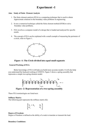
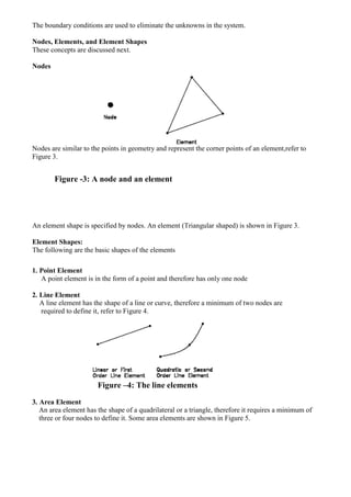
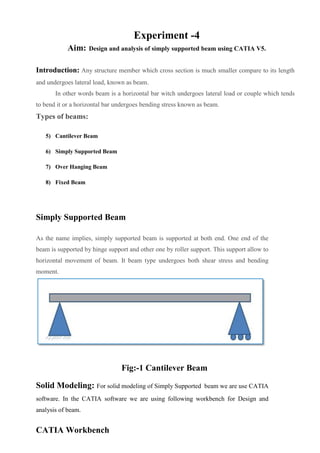
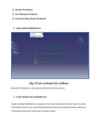
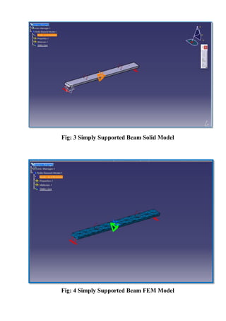
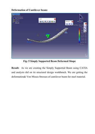
NAME :
ROLL NO :
BRANCH :
Baderia Global Group of Institution, Jabalpur
Department of Mechanical Engineering, BGGI, Jabalpur
B. Tech
III Year (V Semester)
Lab Manual
Of
“Finite Element Method”
SARANG SHRIVAS
0225ME191111
MECHANICAL ENGINEERING
List of Experiments
S.NO. TOPIC DATE SIGN
1 Study of Finite Element Analysis
2 Study of solid modeling using
CATIA
3 Design and analysis of
cantilever beam using CATIA
V5.
4 Design and analysis of simply
supported beam using CATIA
V5.
5 Design and FEA analysis bend
rod using CATIA V5.
Experiment -1
Aim: Study of Finite Element Analysis
1. The finite element analysis (FEA) is a computing technique that is used to obtain
Approximate solutions to the boundary value problems in engineering.
2. It uses a numerical technique called the finite element method (FEM) to solve
boundary value problems.
3. FEA involves a computer model of a design that is loaded and analyzed for specific
results
4. The concept of FEA can be explained with a small example of measuring the perimeter of
a circle, refer to Figure 1.
Figure -1: The Circle divided into equal small segments
General Working of FEA:
Better knowledge of FEA will help you build more accurate models. It will also help
you understand the backend working of ANSYS. Figure 2 shows a spring assembly that
represents a simple two-spring element model.
Figure -2: Representation of a two-spring assembly
These FEA terminologies are listed next.
Stiffness Matrix:
The following part represents the stiffness matrix (K):
Degree of Freedom:
Degree of freedom is defined as the ability of a node to translate or transmit the load.
Boundary Conditions:
The boundary conditions are used to eliminate the unknowns in the system.
Nodes, Elements, and Element Shapes
These concepts are discussed next.
Nodes
Nodes are similar to the points in geometry and represent the corner points of an element,refer to
Figure 3.
Figure -3: A node and an element
An element shape is specified by nodes. An element (Triangular shaped) is shown in Figure 3.
Element Shapes:
The following are the basic shapes of the elements
1. Point Element
A point element is in the form of a point and therefore has only one node
2. Line Element
A line element has the shape of a line or curve, therefore a minimum of two nodes are
required to define it, refer to Figure 4.
Figure –4: The line elements
3. Area Element
An area element has the shape of a quadrilateral or a triangle, therefore it requires a minimum of
three or four nodes to define it. Some area elements are shown in Figure 5.
Figure-5: The area elements
4. Volume Element
A volume element has the shape of a hexahedron (8 nodes), wedge (6 nodes), tetrahedron (4
nodes) or a pyramid (5 nodes). Some of the volume elements are shown in Figure 6.
Figure-6: The volume elements
General Procedure of Conducting Finite Element Analysis:
1. Set the type of analysis to be used.
2. Create the model.
3. Define the element type.
4. Divide the given problem into nodes and elements (mesh the model).
5. Apply material properties and boundary conditions.
6. Derive the element matrices and equations.
7. Assemble the element equations.
8. Solve the unknown quantities at nodes.
9. Interpret the results.
FEA through ANSYS:
In ANSYS, the general process of finite element analysis is divided into three main
phases, preprocessor, solution and postprocessor. Refer Figure-7.
Figure-7: FEA through ANSYS
Preprocessor
The preprocessor is a program that processes the input data to produce the output that is
used as input to the subsequent phase (solution), refer to Figure 7.
Solution
Solution phase is completely automatic. The FEA software generates the element
matrices, computes nodal values and derivatives, and stores the result data in files.
Postprocessor
The output from the solution phase (result data files) is in the numerical form and
consists of nodal values of the field variable and its derivatives.
Effective Utilization of FEA
Some prerequisites for effective utilization of FEA from engineers and FEA software are
discussed next.
Engineers
An engineer who wants to work with this tool should have sound knowledge of Strength of
Materials (for structural analysis), Heat Transfer, Thermodynamics (for thermal analysis), and a
good analytical/designing skill.
Software
The FEA software should be selected based on the following considerations:
1. Analysis type to be performed.
2. Flexibility and accuracy of the tool.
3. Hardware configuration of your system.
FEA Software
There are varieties of commercial FEA software packages available in market. Some of the
most popular and commercially available FEA software are as follows:
1. ANSYS
2. Adina
3. Abaqus
4. Hypermesh
5. NX Nastran
6. Cosmos
7. NISA
8. Marc
9. Ls-Dyna
10. MSC/Dytran
11. Star-CD
ANSYS developed by ANSYS, Inc., USA, is a dedicated Computer Aided Finite Element Modeling
and Finite Element Analysis tool. ANSYS is known as the standard in the field of Computer Aided
Engineering. The Graphical User Interface (GUI) of ANSYS enables the user to work with 3-
dimensional (3D) models and also generate results from them.
SYSTEM REQUIREMENTS:
1. System unit: An Intel Pentium 4 or AMD 64, running Microsoft 2000
Professional Edition, Windows XP 32-bit, or Windows XP x64 on it.
2. Memory: 512 MB of RAM is the minimum requirement for all applications.
However, for 64-bit systems, 1 GB of RAM is the minimum requirement.
3. Disk drive: 2.2 GB Disk Drive space (Minimum recommended size).
4. A DVD drive: is required for the program installation.
5. Graphics adapter: Graphics card compatible with the supported operating
systems, capable of supporting 1024x768 High Color (16-bit), and a 17- inch
monitor compatible with this type of graphics card.
Experiment -2
Aim: Study of solid modeling using CATIA
1. CATIA Stands for Computer Aided Three Dimensional Interactive Application.
2. CATIA V5, developed by Dassault Systems-France, is a completely re-engineered,
next-generation family of CAD/CAM/CAE software solutions for Product Lifecycle
Management.
3. CATIA V5 serves the basic design tasks by providing different workbenches.
4. A workbench is defined as a specified environment consisting of a set of tools, which
allow the user to perform the specific design tasks in a particular area.
The basic workbenches available in CATIA V5 are:
Part Design Workbench
The Part Design workbench is a parametric and feature-based environment, in which you we
can create solid models.
Wireframe and Surface Design Workbench
1. The Wireframe and Surface Design workbench is also a parametric and feature - based
environment, in which you can create wireframe or surface models.
2. The tools in this workbench are similar to those in the Part Design workbench, with the
only difference that the tools in this environment are used to create basic and advanced
surfaces.
Assembly Design Workbench
1. The Assembly Design workbench is used to assemble the components using the
assembly constraints available in this workbench.
2. There are two types of assembly design approaches:
1. Bottom-up
2. Top-down
Drafting Workbench
1. The Drafting workbench is used for the documentation of the parts or the assemblies
created earlier in the form of drawing views and their detailing.
2. There are two types of drafting techniques:
1. Generative drafting
2. Interactive drafting
SYSTEM REQUIREMENTS:
The following are the system requirements to ensure smooth running of CATIA
V5R16 on our system:
• System unit: An Intel Pentium III or Pentium 4 based workstation running Microsoft
2000 Professional Edition or Windows XP Professional Edition.
• Memory: 256 MB of RAM is the minimum recommended for all applications. 512
MB of RAM is recommended for DMU applications.
• Disk drive: 4 GB Disk Drive space (Minimum recommended size)
• Internal/External drives: A CD-ROM drive is required for program installation.
•Display: A graphic color display compatible with the selected platform-specific
graphic adapter. The minimum recommended monitor size is 17 inches.
•Graphics adapter: A graphics adapter with a 3D OpenGL accelerator is required with
minimum resolution of 1024x768 for Microsoft Windows workstations and
1280 x 1024 for UNIX workstations.
IMPORTANT TERMS AND DEFINITIONS:
Feature-based Modeling
• A feature is defined as the smallest building block that can be modified individually.
• A model created in CATIA V5 is a combination of a number of individual features and
each feature is related to the other directly or indirectly.
Parametric Modeling
The parametric nature of a software package is defined as its ability to use the
Standard properties or parameters in defining the shape and size of a geometry.
CAT Part
CAT Part is a file extension associated with all the files that are created in
Sketcher, Part Design, and Wireframe and Surface Design workbenches of
CATIA V5.
CAT Product
CAT Product is a file extension associated with all the files that are created in
Assembly Design workbench of CATIA V5.
CAT Drawing
CAT Drawing is a file extension associated with all the files that are created in
Drafting workbench of CATIA V5.
Specification Tree
1. The specification tree keeps a track of all the operations that are carried on the
part, as shown in the figure.
2.The specification tree that appears when you start a new file under the Part
Design workbench, is as shown in the figure.
FIG.:The specification tree that appears on starting a new CAT Part file
Compass
1. It is a tool that is used to manipulate the orientation of parts, assemblies, or
sketches.
2. You can also orient the view of the parts and assemblies.
3. By default, it appears on the top right corner of the geometry area.
Constraints:
The Compass
1. Constraints are logical operations that are performed on the selected element to define its
size and location with respect to other elements or reference geometries.
2. The constraints in Sketcher workbench are called geometric constraints and the
constraints available in the Assembly Design workbench are called assembly constraints.
Geometric Constraints:
These are the logical operations performed on sketched elements to define their size
and position with respect to other elements.
Exercise 1
Aim: To draw the sketch of the model shown in Figure A. The sketch is shown in Figure B.
You will not dimension the sketch. The solid model and the dimensions are given only for
your reference.
Figure( A): The solid model
Figure (B): The sketch of the model
Procedure:
1. Start CATIA V5 and then start a new CAT part file.
2. Draw the sketch of the model using the Line, Arc, and Circle tools, as shown in Figure
C and Figure D.
Figure (C): The outer loop of the sketch
Figure (D): The final sketch for Exercise - 1
3. Save the file.
Result: Hence the required diagram is created using solid works.
Experiment -3
Aim: Design and analysis of cantilever beam using CATIA V5.
Introduction: Any structure member which cross section is much smaller compare to its length
and undergoes lateral load, known as beam.
In other words beam is a horizontal bar witch undergoes lateral load or couple which tends
to bend it or a horizontal bar undergoes bending stress known as beam.
Types of beams:
1) Cantilever Beam
2) Simply Supported Beam
3) Over Hanging Beam
4) Fixed Beam
Cantilever Beam:
Cantilever beams a structure member of which one end is fixed and other is free. This is
one of the famous type of beam use in trusses, bridges and other structure member. This
beam carry load over the span which undergoes both shear stress and bending moment.
Fig:-1 Cantilever Beam
Solid Modeling: For solid modeling of cantilever beam we are use CATIA
software. In the CATIA software we are using following workbench for Design and
analysis of beam.
CATIA Workbench
1) Sketcher Workbench
2) Part Modeling Workbench
3) Generative Shape Design Workbench
1. SKETCHER WORKBENCH
Fig: 2 Cross sectional View of Beam
In sketcher Workbench we are create the 2d sketch of cantilever beam.
2. PART MODELING WORKBENCH
In part modeling workbench we are going to create solid modeling of cantilever beam. For create
solid model of beam we are using Pad Command and using Steel material for further analysis use.
The diagram showing the solid model of cantilever beam,
Fig: 3 Cantilever Beam Solid Model
Fig: 4 Cantilever Beam FEM Model
Deformation of Cantilever beam:
Fig: 5 Cantilever Deformed Shape
Result: As we are creating the cantilever beam using CATIA and
analysis done on its structural design workbench. We are getting the
deformation& Von Misses Stresses of cantilever beam for steel material.
Experiment -4
Aim: Design and analysis of simply supported beam using CATIA V5.
Introduction: Any structure member which cross section is much smaller compare to its length
and undergoes lateral load, known as beam.
In other words beam is a horizontal bar witch undergoes lateral load or couple which tends
to bend it or a horizontal bar undergoes bending stress known as beam.
Types of beams:
5) Cantilever Beam
6) Simply Supported Beam
7) Over Hanging Beam
8) Fixed Beam
Simply Supported Beam
As the name implies, simply supported beam is supported at both end. One end of the
beam is supported by hinge support and other one by roller support. This support allow to
horizontal movement of beam. It beam type undergoes both shear stress and bending
moment.
Fig:-1 Cantilever Beam
Solid Modeling: For solid modeling of Simply Supported beam we are use CATIA
software. In the CATIA software we are using following workbench for Design and
analysis of beam.
CATIA Workbench
4) Sketcher Workbench
5) Part Modeling Workbench
6) Generative Shape Design Workbench
3. SKETCHER WORKBENCH
Fig: 2 Cross sectional View of Beam
In sketcher Workbench we are create the 2d sketch of cantilever beam.
4. PART MODELING WORKBENCH
In part modeling workbench we are going to create solid modeling of cantilever beam. For create
solid model of beam we are using Pad Command and using Steel material for further analysis use.
The diagram showing the solid model of cantilever beam,
Fig: 3 Simply Supported Beam Solid Model
Fig: 4 Simply Supported Beam FEM Model
Deformation of Cantilever beam:
Fig: 5 Simply Supported Beam Deformed Shape
Result: As we are creating the Simply Supported Beam using CATIA
and analysis did on its structural design workbench. We are getting the
deformation& Von Misses Stresses of cantilever beam for steel material.
Experiment -5
Aim: Design and FEA analysis bend rod using CATIA V5.
Introduction: Bend is a generic term for any offset or change of direction in the piping. It is a
vague term that also includes elbows. An elbow is an engineering term and they are classified as 90
deg or 45 deg, short or long radius.
Design of Bend Pipe: For Creating the the bend Pipe We are using CATIA software For solid
Modeling .For Creating the solid model of bend pipe we are creating 2d Geometry then we are
going to create the solid model of bend Pipe.
Fig:-1 Path of Bend pipe
Fig:-2 Profile of Bend pipe
Modeling of bend pipe: For creating the bend pipe we are using CATIA
software for creating solid model of bend pipe. For creating the solid model of bend
pipe we are creating the 2d sketch of path of bend pipe in sketch workbench.
Then after creating the path of bend pipe we create the profile of pipe in
perpendicular plane to the path.
After creating Both path and profile workbench shifted to part design. In that
workbench we are using Rib command for creating solid model of bend pipe.
The diagram represents the solid model of bend pipe.
Fig: 3 Solid Model of Bend Pipe
Meshing: Meshing is the process in which the continuous geometric space of an
object is broken down into thousands or more of shapes to properly define the
physical shape of the object. The more detailed a mesh is, the more accurate the 3D
CAD model will be, allowing for high fidelity simulations
For FEA analysis of bend pipe we are using static structural analysis
workbench using CATIA.
Fig: 4 Mesh view Deformed Shape of Bend Pipe
Result: Bend pipe analysis gives the Von Misses Stress of given bend pipe for given
boundary condition Using FEA Analysis using CATIA.

Fem lab manual 2

  • 1.
    NAME : ROLL NO: BRANCH : Baderia Global Group of Institution, Jabalpur Department of Mechanical Engineering, BGGI, Jabalpur B. Tech III Year (V Semester) Lab Manual Of “Finite Element Method” SARANG SHRIVAS 0225ME191111 MECHANICAL ENGINEERING
  • 2.
    List of Experiments S.NO.TOPIC DATE SIGN 1 Study of Finite Element Analysis 2 Study of solid modeling using CATIA 3 Design and analysis of cantilever beam using CATIA V5. 4 Design and analysis of simply supported beam using CATIA V5. 5 Design and FEA analysis bend rod using CATIA V5.
  • 3.
    Experiment -1 Aim: Studyof Finite Element Analysis 1. The finite element analysis (FEA) is a computing technique that is used to obtain Approximate solutions to the boundary value problems in engineering. 2. It uses a numerical technique called the finite element method (FEM) to solve boundary value problems. 3. FEA involves a computer model of a design that is loaded and analyzed for specific results 4. The concept of FEA can be explained with a small example of measuring the perimeter of a circle, refer to Figure 1. Figure -1: The Circle divided into equal small segments General Working of FEA: Better knowledge of FEA will help you build more accurate models. It will also help you understand the backend working of ANSYS. Figure 2 shows a spring assembly that represents a simple two-spring element model. Figure -2: Representation of a two-spring assembly These FEA terminologies are listed next. Stiffness Matrix: The following part represents the stiffness matrix (K): Degree of Freedom: Degree of freedom is defined as the ability of a node to translate or transmit the load. Boundary Conditions:
  • 4.
    The boundary conditionsare used to eliminate the unknowns in the system. Nodes, Elements, and Element Shapes These concepts are discussed next. Nodes Nodes are similar to the points in geometry and represent the corner points of an element,refer to Figure 3. Figure -3: A node and an element An element shape is specified by nodes. An element (Triangular shaped) is shown in Figure 3. Element Shapes: The following are the basic shapes of the elements 1. Point Element A point element is in the form of a point and therefore has only one node 2. Line Element A line element has the shape of a line or curve, therefore a minimum of two nodes are required to define it, refer to Figure 4. Figure –4: The line elements 3. Area Element An area element has the shape of a quadrilateral or a triangle, therefore it requires a minimum of three or four nodes to define it. Some area elements are shown in Figure 5.
  • 5.
    Figure-5: The areaelements 4. Volume Element A volume element has the shape of a hexahedron (8 nodes), wedge (6 nodes), tetrahedron (4 nodes) or a pyramid (5 nodes). Some of the volume elements are shown in Figure 6. Figure-6: The volume elements General Procedure of Conducting Finite Element Analysis: 1. Set the type of analysis to be used. 2. Create the model. 3. Define the element type. 4. Divide the given problem into nodes and elements (mesh the model). 5. Apply material properties and boundary conditions. 6. Derive the element matrices and equations. 7. Assemble the element equations. 8. Solve the unknown quantities at nodes. 9. Interpret the results. FEA through ANSYS: In ANSYS, the general process of finite element analysis is divided into three main phases, preprocessor, solution and postprocessor. Refer Figure-7.
  • 6.
    Figure-7: FEA throughANSYS Preprocessor The preprocessor is a program that processes the input data to produce the output that is used as input to the subsequent phase (solution), refer to Figure 7. Solution Solution phase is completely automatic. The FEA software generates the element matrices, computes nodal values and derivatives, and stores the result data in files. Postprocessor The output from the solution phase (result data files) is in the numerical form and consists of nodal values of the field variable and its derivatives. Effective Utilization of FEA Some prerequisites for effective utilization of FEA from engineers and FEA software are discussed next. Engineers An engineer who wants to work with this tool should have sound knowledge of Strength of Materials (for structural analysis), Heat Transfer, Thermodynamics (for thermal analysis), and a good analytical/designing skill. Software The FEA software should be selected based on the following considerations: 1. Analysis type to be performed. 2. Flexibility and accuracy of the tool. 3. Hardware configuration of your system. FEA Software There are varieties of commercial FEA software packages available in market. Some of the most popular and commercially available FEA software are as follows: 1. ANSYS 2. Adina 3. Abaqus 4. Hypermesh 5. NX Nastran
  • 7.
    6. Cosmos 7. NISA 8.Marc 9. Ls-Dyna 10. MSC/Dytran 11. Star-CD ANSYS developed by ANSYS, Inc., USA, is a dedicated Computer Aided Finite Element Modeling and Finite Element Analysis tool. ANSYS is known as the standard in the field of Computer Aided Engineering. The Graphical User Interface (GUI) of ANSYS enables the user to work with 3- dimensional (3D) models and also generate results from them. SYSTEM REQUIREMENTS: 1. System unit: An Intel Pentium 4 or AMD 64, running Microsoft 2000 Professional Edition, Windows XP 32-bit, or Windows XP x64 on it. 2. Memory: 512 MB of RAM is the minimum requirement for all applications. However, for 64-bit systems, 1 GB of RAM is the minimum requirement. 3. Disk drive: 2.2 GB Disk Drive space (Minimum recommended size). 4. A DVD drive: is required for the program installation. 5. Graphics adapter: Graphics card compatible with the supported operating systems, capable of supporting 1024x768 High Color (16-bit), and a 17- inch monitor compatible with this type of graphics card.
  • 8.
    Experiment -2 Aim: Studyof solid modeling using CATIA 1. CATIA Stands for Computer Aided Three Dimensional Interactive Application. 2. CATIA V5, developed by Dassault Systems-France, is a completely re-engineered, next-generation family of CAD/CAM/CAE software solutions for Product Lifecycle Management. 3. CATIA V5 serves the basic design tasks by providing different workbenches. 4. A workbench is defined as a specified environment consisting of a set of tools, which allow the user to perform the specific design tasks in a particular area. The basic workbenches available in CATIA V5 are: Part Design Workbench The Part Design workbench is a parametric and feature-based environment, in which you we can create solid models. Wireframe and Surface Design Workbench 1. The Wireframe and Surface Design workbench is also a parametric and feature - based environment, in which you can create wireframe or surface models. 2. The tools in this workbench are similar to those in the Part Design workbench, with the only difference that the tools in this environment are used to create basic and advanced surfaces. Assembly Design Workbench 1. The Assembly Design workbench is used to assemble the components using the assembly constraints available in this workbench. 2. There are two types of assembly design approaches: 1. Bottom-up 2. Top-down Drafting Workbench 1. The Drafting workbench is used for the documentation of the parts or the assemblies created earlier in the form of drawing views and their detailing. 2. There are two types of drafting techniques: 1. Generative drafting 2. Interactive drafting SYSTEM REQUIREMENTS: The following are the system requirements to ensure smooth running of CATIA V5R16 on our system:
  • 9.
    • System unit:An Intel Pentium III or Pentium 4 based workstation running Microsoft 2000 Professional Edition or Windows XP Professional Edition. • Memory: 256 MB of RAM is the minimum recommended for all applications. 512 MB of RAM is recommended for DMU applications. • Disk drive: 4 GB Disk Drive space (Minimum recommended size) • Internal/External drives: A CD-ROM drive is required for program installation. •Display: A graphic color display compatible with the selected platform-specific graphic adapter. The minimum recommended monitor size is 17 inches. •Graphics adapter: A graphics adapter with a 3D OpenGL accelerator is required with minimum resolution of 1024x768 for Microsoft Windows workstations and 1280 x 1024 for UNIX workstations. IMPORTANT TERMS AND DEFINITIONS: Feature-based Modeling • A feature is defined as the smallest building block that can be modified individually. • A model created in CATIA V5 is a combination of a number of individual features and each feature is related to the other directly or indirectly. Parametric Modeling The parametric nature of a software package is defined as its ability to use the Standard properties or parameters in defining the shape and size of a geometry. CAT Part CAT Part is a file extension associated with all the files that are created in Sketcher, Part Design, and Wireframe and Surface Design workbenches of CATIA V5. CAT Product CAT Product is a file extension associated with all the files that are created in Assembly Design workbench of CATIA V5. CAT Drawing CAT Drawing is a file extension associated with all the files that are created in Drafting workbench of CATIA V5. Specification Tree
  • 10.
    1. The specificationtree keeps a track of all the operations that are carried on the part, as shown in the figure. 2.The specification tree that appears when you start a new file under the Part Design workbench, is as shown in the figure. FIG.:The specification tree that appears on starting a new CAT Part file Compass 1. It is a tool that is used to manipulate the orientation of parts, assemblies, or sketches. 2. You can also orient the view of the parts and assemblies. 3. By default, it appears on the top right corner of the geometry area. Constraints: The Compass 1. Constraints are logical operations that are performed on the selected element to define its size and location with respect to other elements or reference geometries. 2. The constraints in Sketcher workbench are called geometric constraints and the constraints available in the Assembly Design workbench are called assembly constraints. Geometric Constraints: These are the logical operations performed on sketched elements to define their size and position with respect to other elements.
  • 11.
    Exercise 1 Aim: Todraw the sketch of the model shown in Figure A. The sketch is shown in Figure B. You will not dimension the sketch. The solid model and the dimensions are given only for your reference. Figure( A): The solid model Figure (B): The sketch of the model Procedure:
  • 12.
    1. Start CATIAV5 and then start a new CAT part file. 2. Draw the sketch of the model using the Line, Arc, and Circle tools, as shown in Figure C and Figure D. Figure (C): The outer loop of the sketch Figure (D): The final sketch for Exercise - 1 3. Save the file. Result: Hence the required diagram is created using solid works.
  • 13.
    Experiment -3 Aim: Designand analysis of cantilever beam using CATIA V5. Introduction: Any structure member which cross section is much smaller compare to its length and undergoes lateral load, known as beam. In other words beam is a horizontal bar witch undergoes lateral load or couple which tends to bend it or a horizontal bar undergoes bending stress known as beam. Types of beams: 1) Cantilever Beam 2) Simply Supported Beam 3) Over Hanging Beam 4) Fixed Beam Cantilever Beam: Cantilever beams a structure member of which one end is fixed and other is free. This is one of the famous type of beam use in trusses, bridges and other structure member. This beam carry load over the span which undergoes both shear stress and bending moment. Fig:-1 Cantilever Beam Solid Modeling: For solid modeling of cantilever beam we are use CATIA software. In the CATIA software we are using following workbench for Design and analysis of beam.
  • 14.
    CATIA Workbench 1) SketcherWorkbench 2) Part Modeling Workbench 3) Generative Shape Design Workbench 1. SKETCHER WORKBENCH Fig: 2 Cross sectional View of Beam In sketcher Workbench we are create the 2d sketch of cantilever beam. 2. PART MODELING WORKBENCH In part modeling workbench we are going to create solid modeling of cantilever beam. For create solid model of beam we are using Pad Command and using Steel material for further analysis use. The diagram showing the solid model of cantilever beam,
  • 15.
    Fig: 3 CantileverBeam Solid Model Fig: 4 Cantilever Beam FEM Model
  • 16.
    Deformation of Cantileverbeam: Fig: 5 Cantilever Deformed Shape Result: As we are creating the cantilever beam using CATIA and analysis done on its structural design workbench. We are getting the deformation& Von Misses Stresses of cantilever beam for steel material.
  • 17.
    Experiment -4 Aim: Designand analysis of simply supported beam using CATIA V5. Introduction: Any structure member which cross section is much smaller compare to its length and undergoes lateral load, known as beam. In other words beam is a horizontal bar witch undergoes lateral load or couple which tends to bend it or a horizontal bar undergoes bending stress known as beam. Types of beams: 5) Cantilever Beam 6) Simply Supported Beam 7) Over Hanging Beam 8) Fixed Beam Simply Supported Beam As the name implies, simply supported beam is supported at both end. One end of the beam is supported by hinge support and other one by roller support. This support allow to horizontal movement of beam. It beam type undergoes both shear stress and bending moment. Fig:-1 Cantilever Beam Solid Modeling: For solid modeling of Simply Supported beam we are use CATIA software. In the CATIA software we are using following workbench for Design and analysis of beam. CATIA Workbench
  • 18.
    4) Sketcher Workbench 5)Part Modeling Workbench 6) Generative Shape Design Workbench 3. SKETCHER WORKBENCH Fig: 2 Cross sectional View of Beam In sketcher Workbench we are create the 2d sketch of cantilever beam. 4. PART MODELING WORKBENCH In part modeling workbench we are going to create solid modeling of cantilever beam. For create solid model of beam we are using Pad Command and using Steel material for further analysis use. The diagram showing the solid model of cantilever beam,
  • 19.
    Fig: 3 SimplySupported Beam Solid Model Fig: 4 Simply Supported Beam FEM Model
  • 20.
    Deformation of Cantileverbeam: Fig: 5 Simply Supported Beam Deformed Shape Result: As we are creating the Simply Supported Beam using CATIA and analysis did on its structural design workbench. We are getting the deformation& Von Misses Stresses of cantilever beam for steel material.
  • 21.
    Experiment -5 Aim: Designand FEA analysis bend rod using CATIA V5. Introduction: Bend is a generic term for any offset or change of direction in the piping. It is a vague term that also includes elbows. An elbow is an engineering term and they are classified as 90 deg or 45 deg, short or long radius. Design of Bend Pipe: For Creating the the bend Pipe We are using CATIA software For solid Modeling .For Creating the solid model of bend pipe we are creating 2d Geometry then we are going to create the solid model of bend Pipe. Fig:-1 Path of Bend pipe Fig:-2 Profile of Bend pipe
  • 22.
    Modeling of bendpipe: For creating the bend pipe we are using CATIA software for creating solid model of bend pipe. For creating the solid model of bend pipe we are creating the 2d sketch of path of bend pipe in sketch workbench. Then after creating the path of bend pipe we create the profile of pipe in perpendicular plane to the path. After creating Both path and profile workbench shifted to part design. In that workbench we are using Rib command for creating solid model of bend pipe. The diagram represents the solid model of bend pipe. Fig: 3 Solid Model of Bend Pipe Meshing: Meshing is the process in which the continuous geometric space of an object is broken down into thousands or more of shapes to properly define the physical shape of the object. The more detailed a mesh is, the more accurate the 3D CAD model will be, allowing for high fidelity simulations For FEA analysis of bend pipe we are using static structural analysis workbench using CATIA.
  • 23.
    Fig: 4 Meshview Deformed Shape of Bend Pipe Result: Bend pipe analysis gives the Von Misses Stress of given bend pipe for given boundary condition Using FEA Analysis using CATIA.