More Related Content

PDF
Distributed Control System (DCS) Notes 
PPT

PPT

PPT

PPTX
What is a Distributed Control System? DCS has evolved from the original desc... 
PPTX
Distributed control system 
PDF
PLC Training in Noida | PLC Scada Training in Delhi 
PPTX
Basic understanding of PLC RTU DCS SCADA Similar to Basic of Programable Logic Controller PLC

PPTX

PDF
What id difference between .. 
PPTX
DCS Simulator configure program and troubleshooting 
PPTX

PPTX

PPTX
Scada system ( Overview ) 
PPT
Distributed control system PPT 1 2 3 4 5 
PPTX

PPTX
SCADA The Universal Remote for Industrial Control.pptx 
PPTX
DCS - Distributed Control System 
PDF
Lecture+9+-+SCADA+Systems.pdf 
PDF

PPTX
SCADAhjknvbxfbgmmmmmmmmmmmmmmmmmmmmmmm.pptx 
PPTX
Lecture+9+-+SCADA+Systems.pptx 
PDF
Practical DNP3 and Modern SCADA Systems 
PPT
PLC as a digital electronic devic programmable memor 
PPTX
This ppt is about distributed control system. 
PPT

PDF
DCS FTKU DSYJKHJ IUGHGJHJHGHFGDFSHGJHGHFGDFSDAFDGFHG 
PDF
Unit Three.pdfrhykyfgdsfuliuyfgm,i;poiuyrtghkl;ipoiy More from Ahmed Ramadan

PPTX
Basic PLC - Solid introduction _ 22.pptx 
PPTX
Basic PLC - Solid introduction _ 1 .pptx 
PPT
pressure-relief- devices and valves basics 
PDF
Logic Concepts as used in programmable logic controller 
PDF
Introduction to Programmable Controllers 
PPT
Supp HAZOP 1 Hazard Analysis Review: The Concept of Risk 
PPT
Total Solution for Flue Gas Analyzer Series 
PPTX
Compressor Control and Optimization.pptx 
PPT
Distributed Control System Operation seminar 
PPT
FT-IR Instrument Components presentation 
PDF
Part 2 Analytical Measurements techniques. 
PDF
Operation Stations in a Distributed Control System Recently uploaded

PDF
MoD_2.pptx solid rockets of the rocket.pdf 
PPTX
Fuel Injection Pump Test Bench – Precision Testing & Calibration for Diesel E... 
PDF
Microcontroller Notes Final 2016 April june.pdf 
PDF
DAA Lab Manual ssit -kavya r.pdf or Digital Design and Analysis of Algorithm ... 
PPTX
DIFFERENT TYPES OF SRTUCTURAL SYSTEM ANALYSIS 
PDF
AWS Re:Invent 2025 Recap by FivexL - Guilherme, Vladimir, Andrey 
PPTX
INTEGRATED COMMUNICATION AND SENSING Presentation.pptx 
PPTX
ME3592 - Metrology and Measurements - Unit - 1 - Lecture Notes 
PPTX
traffic safety section seven (Traffic Control and Management) of Act 
PDF
(en/zhTW) Heterogeneous System Architecture: Design & Performance 
PDF
Unit Weight in Term of Volumetric Water Content.pdf 
PDF
Weak Incentives (WINK): The Agent Definition Layer 
PDF
Plasticity and Structure of Soil/Atterberg Limits.pdf 
PDF
Enhancing optical fiber communication systems using repetition coding for imp... 
PPTX
Batch-1(End Semester) Student Of Shree Durga Tech. PPT.pptx 
PPTX
Why TPM Succeeds in Some Plants and Struggles in Others | MaintWiz 
PPTX
Presentation-WPS Office.pptx afgouvhyhgfccf 
PPTX
Why Most SAP PM Implementations Fail — And How High-Reliability Plants Fix It 
PPTX
This Bearing Didn’t Fail Suddenly — How Vibration Data Predicts Failure Month... 
PPTX
A professional presentation on Cosmos Bank Heist Basic of Programable Logic Controller PLC
- 1.
- 2.
2 I Copyright© 2024 TPS. All rights reserved
Day 5 Agenda
Overview of typical distributed Control system
architecture
DCS vs. SCADA vs. PLC’s Comparison
The smart instrument
Component in a DCS system
- 3.
3 I Copyright© 2024 TPS. All rights reserved
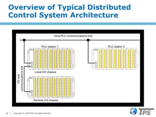
CPU
CPU CPU
CPU
RIO
RIO
Intra-PLC communications link
PLC station 1 PLC station 2
Local I/O chassis
Remote I/O chassis
I/O
rack
communications
link
Overview of Typical Distributed
Control System Architecture
- 4.
4 I Copyright© 2024 TPS. All rights reserved
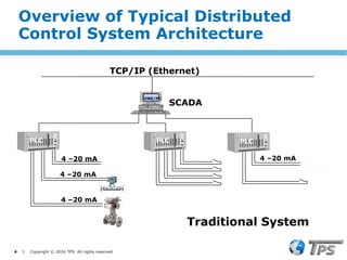
VME/PC
4 –20 mA
4 –20 mA
4 –20 mA
PLC PLC
4 –20 mA
PLC
SCADA
TCP/IP (Ethernet)
Traditional System
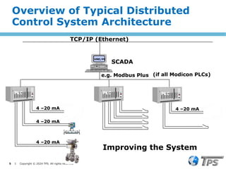
Overview of Typical Distributed
Control System Architecture
- 5.
5 I Copyright© 2024 TPS. All rights reserved
VME/PC
4 –20 mA
4 –20 mA
4 –20 mA
PLC PLC
4 –20 mA
PLC
SCADA
TCP/IP (Ethernet)
e.g. Modbus Plus (if all Modicon PLCs)
Improving the System
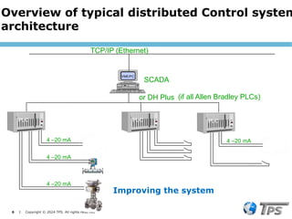
Overview of Typical Distributed
Control System Architecture
- 6.
6 I Copyright© 2024 TPS. All rights reserved
VME/PC
4 –20 mA
4 –20 mA
4 –20 mA
PLC PLC
4 –20 mA
PLC
SCADA
TCP/IP (Ethernet)
or DH Plus (if all Allen Bradley PLCs)
Improving the system
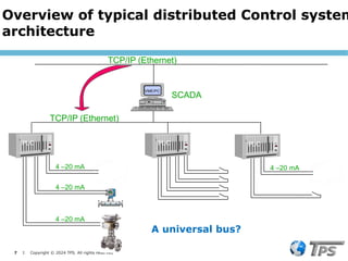
Overview of typical distributed Control system
architecture
- 7.
7 I Copyright© 2024 TPS. All rights reserved
VME/PC
4 –20 mA
4 –20 mA
4 –20 mA
PLC PLC
4 –20 mA
PLC
SCADA
TCP/IP (Ethernet)
TCP/IP (Ethernet)
A universal bus?
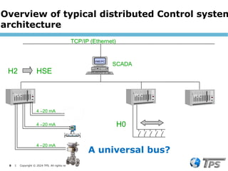
Overview of typical distributed Control system
architecture
- 8.
8 I Copyright© 2024 TPS. All rights reserved
VME/PC
PLC PLC PLC
SCADA
TCP/IP (Ethernet)
H2 HSE
H0
4 –20 mA
4 –20 mA
4 –20 mA
A universal bus?
Overview of typical distributed Control system
architecture
- 9.
9 I Copyright© 2024 TPS. All rights reserved
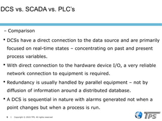
DCSs have a direct connection to the data source and are primarily
focused on real-time states – concentrating on past and present
process variables.
With direct connection to the hardware device I/O, a very reliable
network connection to equipment is required.
Redundancy is usually handled by parallel equipment – not by
diffusion of information around a distributed database.
A DCS is sequential in nature with alarms generated not when a
point changes but when a process is run.
DCS vs. SCADA vs. PLC’s
– Comparison
- 10.
10 I Copyright© 2024 TPS. All rights reserved
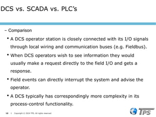
A DCS operator station is closely connected with its I/O signals
through local wiring and communication buses (e.g. Fieldbus).
When DCS operators wish to see information they would
usually make a request directly to the field I/O and gets a
response.
Field events can directly interrupt the system and advise the
operator.
A DCS typically has correspondingly more complexity in its
process-control functionality.
DCS vs. SCADA vs. PLC’s
– Comparison
- 11.
11 I Copyright© 2024 TPS. All rights reserved
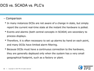
In many instances DCSs are not aware of a change in state, but simply
report the current real-time state at the instant the hardware is polled.
Events and alarms (both central concepts in SCADA) are secondary to
process displays.
Therefore, it is often necessary to set up alarms by hand on each point,
and many DCSs have limited alarm filtering.
Because DCSs must have a continuous connection to the hardware,
they are generally deployed only when the system has a very small
geographical footprint, such as a factory or plant.
DCS vs. SCADA vs. PLC’s
– Comparison
- 12.
12 I Copyright© 2024 TPS. All rights reserved
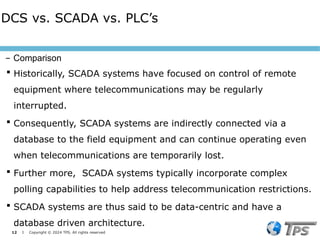
Historically, SCADA systems have focused on control of remote
equipment where telecommunications may be regularly
interrupted.
Consequently, SCADA systems are indirectly connected via a
database to the field equipment and can continue operating even
when telecommunications are temporarily lost.
Further more, SCADA systems typically incorporate complex
polling capabilities to help address telecommunication restrictions.
SCADA systems are thus said to be data-centric and have a
database driven architecture.
DCS vs. SCADA vs. PLC’s
– Comparison
- 13.
13 I Copyright© 2024 TPS. All rights reserved
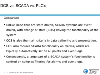
Unlike DCSs that are state driven, SCADA systems are event
driven, with change of state (COS) driving the functionality of the
system
COS is also the main criteria in data gathering and presentation.
COS also focuses SCADA functionality on alarms, which are
typically automatically set on all points and event logs.
Consequently, a large part of a SCADA system's functionality is
centred on complex filtering for alarms and event logs.
DCS vs. SCADA vs. PLC’s
– Comparison
- 14.
14 I Copyright© 2024 TPS. All rights reserved
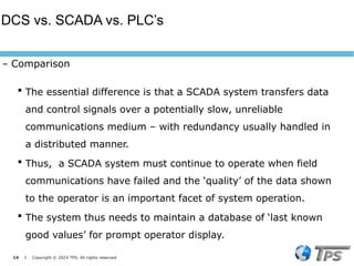
The essential difference is that a SCADA system transfers data
and control signals over a potentially slow, unreliable
communications medium – with redundancy usually handled in
a distributed manner.
Thus, a SCADA system must continue to operate when field
communications have failed and the ‘quality’ of the data shown
to the operator is an important facet of system operation.
The system thus needs to maintain a database of ‘last known
good values’ for prompt operator display.
DCS vs. SCADA vs. PLC’s
– Comparison
- 15.
15 I Copyright© 2024 TPS. All rights reserved
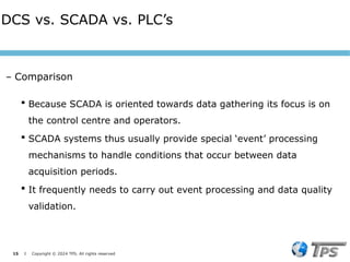
Because SCADA is oriented towards data gathering its focus is on
the control centre and operators.
SCADA systems thus usually provide special ‘event’ processing
mechanisms to handle conditions that occur between data
acquisition periods.
It frequently needs to carry out event processing and data quality
validation.
DCS vs. SCADA vs. PLC’s
– Comparison
- 16.
16 I Copyright© 2024 TPS. All rights reserved
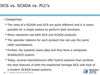
The roles of a SCADA and DCS are quite different and it is rarely
possible for a single system to perform both functions.
Many industries use both DCS and SCADA products.
The operator stations for each product line can use the same
UNIX workstations.
Further, the systems share data and thus form a composite
SCADA/DCS system.
Today, several manufacturers offer hybrid systems that combine
the best features of both the traditional heritage DCS with that of
a modern SCADA-based systems.
DCS vs. SCADA vs. PLC’s
– Comparison
- 17.
17 I Copyright© 2024 TPS. All rights reserved
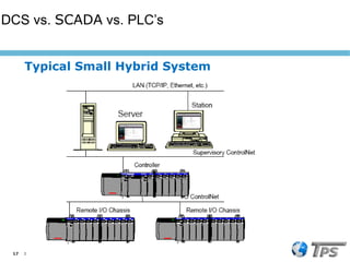
Typical Small Hybrid System
DCS vs. SCADA vs. PLC’s
- 18.
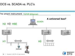
18 I Copyright© 2024 TPS. All rights reserved
VME/PC
PLC PLC PLC
SCADA
TCP/IP (Ethernet)
H2 HSE
H0
H1
A universal bus?
The smart instrument
DCS vs. SCADA vs. PLC’s
- 19.
19 I Copyright© 2024 TPS. All rights reserved
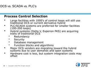
Process Control Selection
Large facilities with 1000’s of control loops will still use
traditional DCS or current derivative hybrid
PLC/SCADA systems are preferred for smaller facilities
(100-200 loops)
Hybrid systems (Delta V, Experion PKS) are acquiring
traits of traditional DCS
• Redundancy
• Security
• Database management
• Function blocks and algorithms
Major DCS vendors are migrating toward the hybrid
systems due to user demands and open systems
Hardware cost is less, but system integration costs may
offset
DCS vs. SCADA vs. PLC’s
- 20.
20 I Copyright© 2024 TPS. All rights reserved
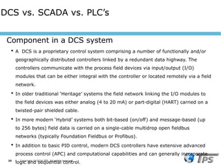
A DCS is a proprietary control system comprising a number of functionally and/or
geographically distributed controllers linked by a redundant data highway. The
controllers communicate with the process field devices via input/output (I/O)
modules that can be either integral with the controller or located remotely via a field
network.
In older traditional ‘Heritage’ systems the field network linking the I/O modules to
the field devices was either analog (4 to 20 mA) or part-digital (HART) carried on a
twisted-pair shielded cable.
In more modern ‘Hybrid’ systems both bit-based (on/off) and message-based (up
to 256 bytes) field data is carried on a single-cable multidrop open fieldbus
networks (typically Foundation Fieldbus or Profibus).
In addition to basic PID control, modern DCS controllers have extensive advanced
process control (APC) and computational capabilities and can generally incorporate
logic and sequential control.
Component in a DCS system
DCS vs. SCADA vs. PLC’s
- 21.
21 I Copyright© 2024 TPS. All rights reserved
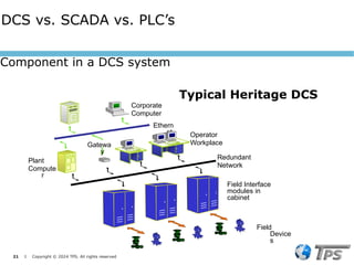
Typical Heritage DCS
Field Interface
modules in
cabinet
Field
Device
s
Ethern
et
Redundant
Network
Corporate
Computer
Plant
Compute
r
Operator
Workplace
Gatewa
y
Component in a DCS system
DCS vs. SCADA vs. PLC’s
- 22.
22 I Copyright© 2024 TPS. All rights reserved
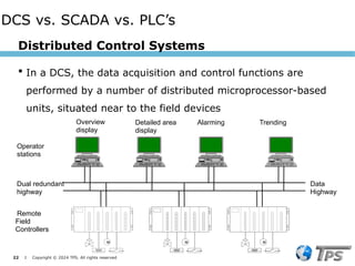
Distributed Control Systems
In a DCS, the data acquisition and control functions are
performed by a number of distributed microprocessor-based
units, situated near to the field devices
Data
Highway
Operator
stations
M
M M
M M
M
Dual redundant
highway
Remote
Field
Controllers
Overview
display
Detailed area
display
Alarming Trending
DCS vs. SCADA vs. PLC’s
- 23.
23 I Copyright© 2024 TPS. All rights reserved
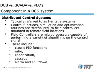
Distributed Control Systems
Typically referred to as Heritage systems
Control functions, simulation and optimization
routines are ‘distributed’ to field controllers
mounted in remote field locations
Field Controllers are microprocessors capable of
performing a variety of algorithms on the control
signal
These include:
• classic PID functions
• ratio,
• linearization,
• cascade,
• alarm and shutdown
Component in a DCS system
DCS vs. SCADA vs. PLC’s
- 24.
- 25.
25 I Copyright© 2024 TPS. All rights reserved
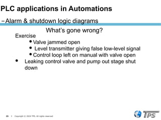
What’s gone wrong?
Exercise
Valve jammed open
Level transmitter giving false low-level signal
Control loop left on manual with valve open
Leaking control valve and pump out stage shut
down
– Alarm & shutdown logic diagrams
PLC applications in Automations
- 26.
26 I Copyright© 2024 TPS. All rights reserved
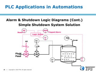
Simple Shutdown System Solution
LT
1
PSV
LC
1
I/P
FC
Fluid
Feed FC
Logic Solver
LT
2
LAHH
2
AS
HS
2
Reset
LI
2
Tripped Alarm
PLC Applications in Automations
Alarm & Shutdown Logic Diagrams (Cont.)
- 27.
27 I Copyright© 2024 TPS. All rights reserved
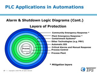
Layers of Protection
Process
Plant Emergency Response *
Other Technologies (e.g. PRV)
Automatic SIS
Critical Alarms and Manual Response
Process Plant
* Mitigation layers
Community Emergency Response *
Containment Systems*
Process Control
PLC Applications in Automations
Alarm & Shutdown Logic Diagrams (Cont.)
- 28.
28 I Copyright© 2024 TPS. All rights reserved
Layers of Protection
‒ A Protection Layer consists of a grouping of
equipment and/or administrative controls that
function in concert with other protection layers
to control or mitigate process risk.
‒ An independent protection layer (IPL):
Reduces the identified risk by at least a factor
of 10.
Has high availability (0.9)
Designed for a specific event
Independent of other protection layers
Dependable and auditable
PLC Applications in Automations
Alarm & Shutdown Logic Diagrams (Cont.)
- 29.
29 I Copyright© 2024 TPS. All rights reserved
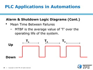
Mean Time Between Failures
‒ MTBF is the average value of ‘T’ over the
operating life of the system.
T1 T2 T3
Up
Down
PLC Applications in Automations
Alarm & Shutdown Logic Diagrams (Cont.)
- 30.
30 I Copyright© 2024 TPS. All rights reserved
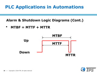
MTBF = MTTF + MTTR
MTTF
MTBF
Up
Down
MTTR
PLC Applications in Automations
Alarm & Shutdown Logic Diagrams (Cont.)
- 31.
31 I Copyright© 2024 TPS. All rights reserved
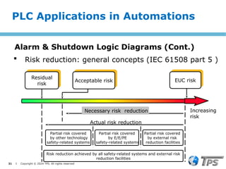
Risk reduction achieved by all safety-related systems and external risk
reduction facilities
Residual
risk
Acceptable risk EUC risk
Necessary risk reduction
Actual risk reduction
Increasing
risk
Partial risk covered
by external risk
reduction facilities
Partial risk covered
by E/E/PE
safety-related systems
Partial risk covered
by other technology
safety-related systems
Risk reduction: general concepts (IEC 61508 part 5 )
PLC Applications in Automations
Alarm & Shutdown Logic Diagrams (Cont.)
- 32.
32 I Copyright© 2024 TPS. All rights reserved
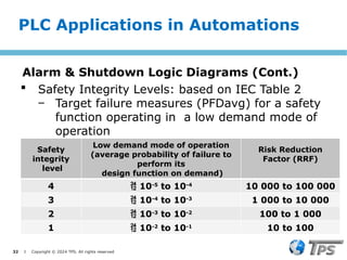
Safety Integrity Levels: based on IEC Table 2
‒ Target failure measures (PFDavg) for a safety
function operating in a low demand mode of
operation
PLC Applications in Automations
Alarm & Shutdown Logic Diagrams (Cont.)
Safety
integrity
level
Low demand mode of operation
(average probability of failure to
perform its
design function on demand)
Risk Reduction
Factor (RRF)
4 10-5
to 10-4
10 000 to 100 000
3 10-4
to 10-3
1 000 to 10 000
2 10-3
to 10-2
100 to 1 000
1 10-2
to 10-1
10 to 100
- 33.
33 I Copyright© 2024 TPS. All rights reserved
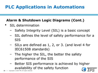
SIL determination
‒ Safety Integrity Level (SIL) is a basic concept
‒ SIL defines the level of safety performance for a
SIS
‒ SILs are defined as 1, 2, or 3. (and level 4 for
IEC61508 standards)
‒ The higher the SIL, the better the safety
performance of the SIS
‒ Better SIS performance is achieved by higher
availability of the safety function
PLC Applications in Automations
Alarm & Shutdown Logic Diagrams (Cont.)
- 34.
34 I Copyright© 2024 TPS. All rights reserved
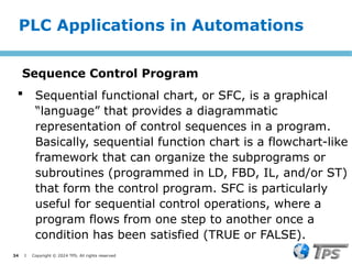
Sequential functional chart, or SFC, is a graphical
“language” that provides a diagrammatic
representation of control sequences in a program.
Basically, sequential function chart is a flowchart-like
framework that can organize the subprograms or
subroutines (programmed in LD, FBD, IL, and/or ST)
that form the control program. SFC is particularly
useful for sequential control operations, where a
program flows from one step to another once a
condition has been satisfied (TRUE or FALSE).
PLC Applications in Automations
Sequence Control Program
- 35.
35 I Copyright© 2024 TPS. All rights reserved
The SFC programming framework contains three
main elements that organize the control program:
‒ Steps
‒ Transitions
‒ Actions
Sequence Control Program (Cont.)
PLC Applications in Automations
- 36.
36 I Copyright© 2024 TPS. All rights reserved
A step is a stage in the control process. For
example, the mixing application has three steps—
the initial step, the mixing step, and the emptying
step. When the control program receives an input, it
will execute each of these steps starting with step 1.
Each step may or may not have an action associated
with it. An action is a set of control instructions
prompting the PLC to execute a certain control
function during that step. An action may be
programmed using any one of the four IEC 1131-3
languages.
PLC Applications in Automations
Sequence Control Program (Cont.)
- 37.
- 38.
38 I Copyright© 2024 TPS. All rights reserved
Lessons In Industrial Instrumentation Rev1.2by
Tony R. Kuphaldt
Programmable Controllers Second Edition by L. A.
Bryan E. A. Bryan
Practical SCADA for industry. By David Bailey &
Edwin Wright
Automation systems and PLCs. By Hugh Jack
Fundamentals of PLCs. By Phil Melore
Principles of User Interface Design. Article by Niall
Murphy
References
- 39.
39 I Copyright© 2024 TPS. All rights reserved
SCADA System Security. Article By Abhishek
Bhattacharjee, Stephen Flannigan and Jens
Nasholm, Citect Inc.
Alarm code in PLCs. Article by Allen Nelson,
PLCs.net
InTouch® Reference Guide. By Invensys Systems,
Inc.
Ethernet Communications Modules. By Automation
Direct, Inc.
Fundamentals of Control 2006 by PAControl.com
References