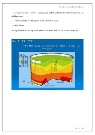
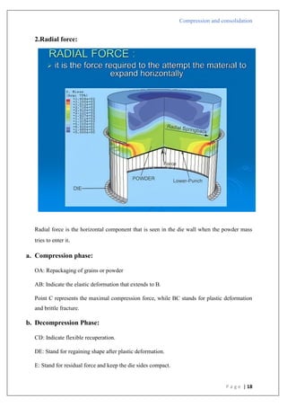
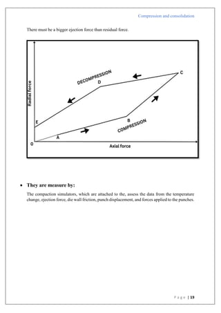
The document is an assignment report detailing the processes of compression and consolidation in tablet formulation within pharmaceutical sciences. It outlines the mechanics and physics of tablet compression, including definitions, steps involved, and the effects of forces during the compaction process. Key topics include particle rearrangement, deformation, bonding theories, and the impact of friction on tablet production, emphasizing the significance of powder properties in achieving the desired tablet quality.

![Compression and consolidation
P a g e | 30
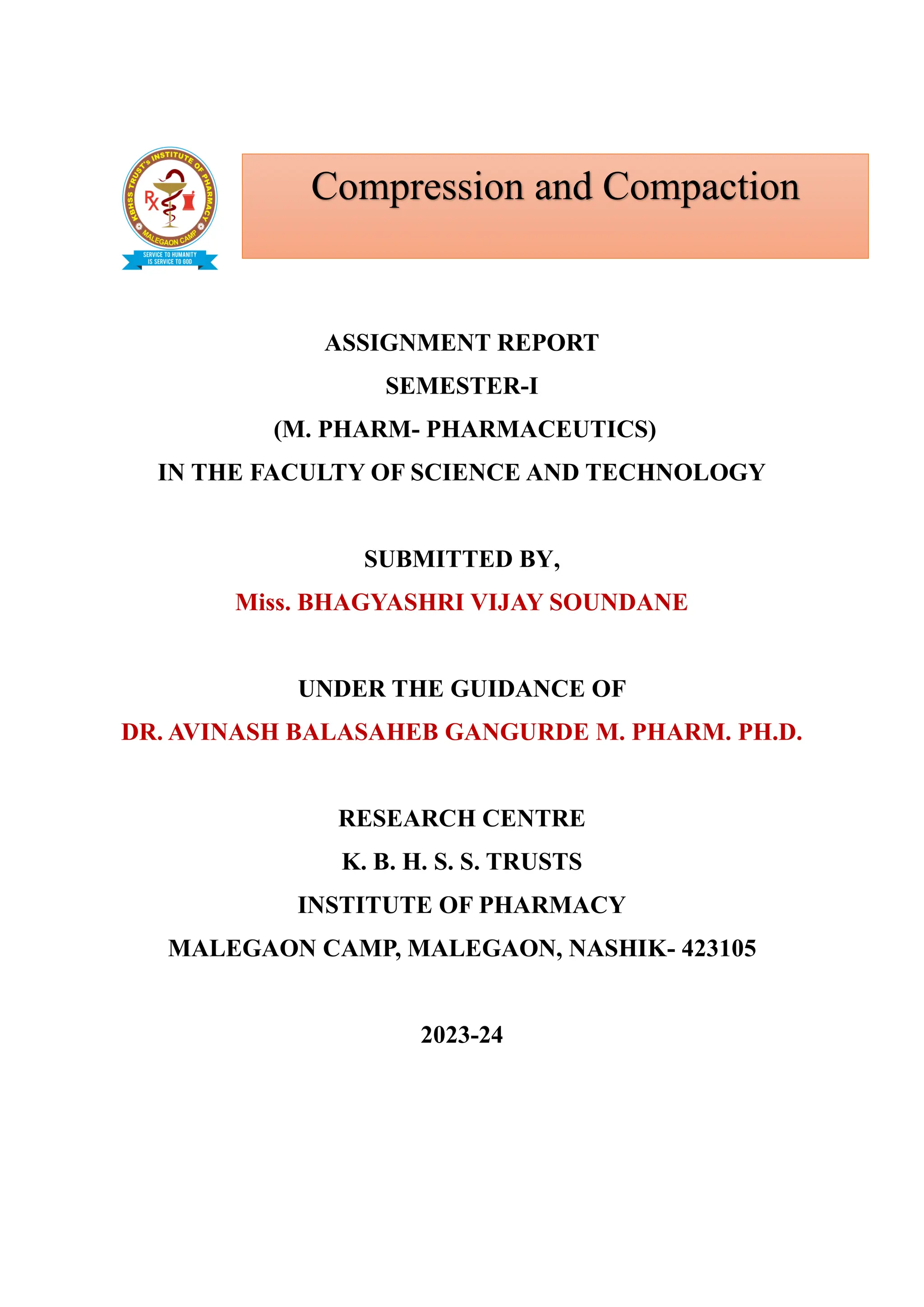
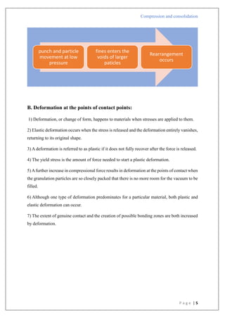
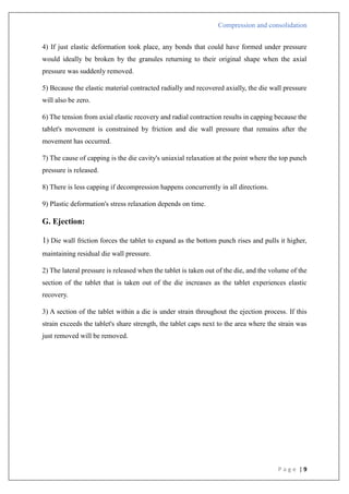
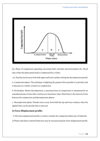
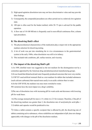
Compression pressure
Type B
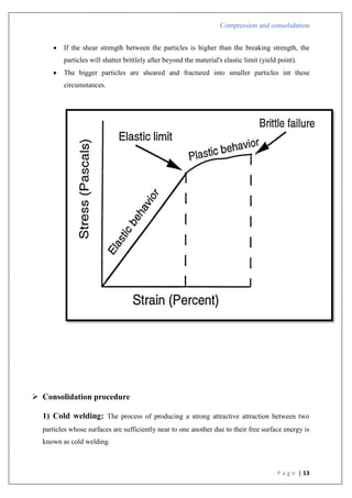
1) There is a straight line that comes after the first curved area.
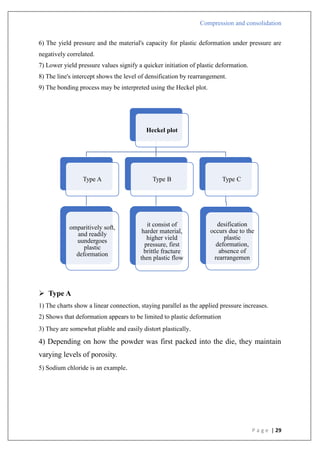
2) Shows that early in the compression phase, the particles begin breaking apart.
3) Plastic flow is preceded by bristle fracture.
4) Take place with stronger materials that have greater yield pressures.
5) To create a denser packing, such materials are first compressed by fragmentation.
6) Lactose as an example.
Type A
In
[1/(1-D)]](https://image.slidesharecdn.com/compressionandcompaction-240930102526-b8ec5d02/85/compression-and-compaction-Physics-of-tablet-compression-pdf-30-320.jpg)
![Compression and consolidation
P a g e | 31
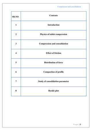
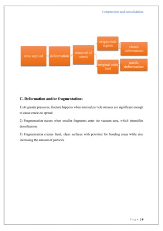
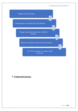
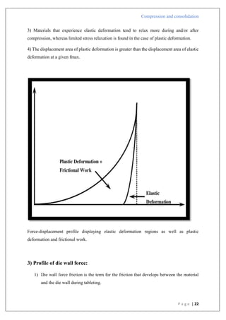
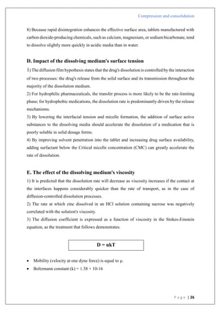
Compression pressure
Type C
1) There is an initial steep linear zone that becomes overlaid in such materials.
2) As more pressure is applied, this overlaid area flattens out.
It was determined that this conduct resulted from the lack of a rearrangement stage.
4) Asperity melting and plastic deformation are the causes of densification.
5) Starch is an example.
Type B
In
[1/(1-D)]](https://image.slidesharecdn.com/compressionandcompaction-240930102526-b8ec5d02/85/compression-and-compaction-Physics-of-tablet-compression-pdf-31-320.jpg)
![Compression and consolidation
P a g e | 32
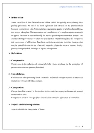
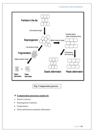
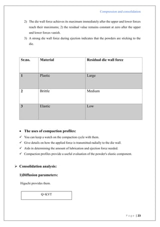
Compression pressure
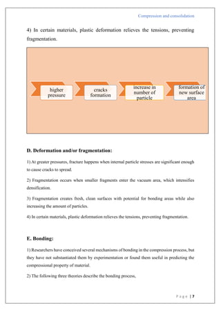
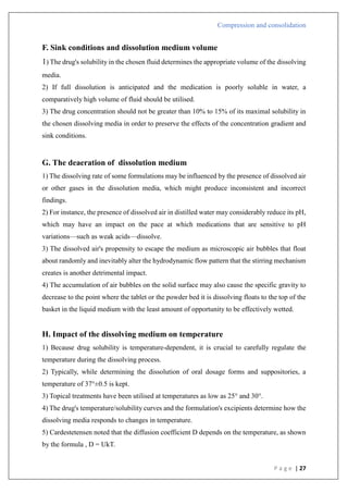
Applications
1) The values of K in the Heckel plot may be used to correlate the crushing strength of tablets;
larger K values correspond to tougher tablets.
2) When creating tablet formulations, binder selection may be done using information from
Heckel plots.
3) The lubricant effectiveness may be verified using the Heckler plot.
4) The consolidation method may be understood by using plot information.
5) Heckel plots are another tool for differentiating between drugs with various accumulation
mechanisms.
6) It may also be applied to evaluate plasticity.
Limitations:
1) A small fluctuation in the real density might affect Heckel graphs.
2) Differences in particle size
3) Total compression time
Type C
In
[1/(1-D)]](https://image.slidesharecdn.com/compressionandcompaction-240930102526-b8ec5d02/85/compression-and-compaction-Physics-of-tablet-compression-pdf-32-320.jpg)


![Physics_of_Tablet_Compression_MP_PPT[1].pptx](https://cdn.slidesharecdn.com/ss_thumbnails/physicsoftabletcompressionmpppt1-250617142628-a6154203-thumbnail.jpg?width=640&height=640&fit=bounds)


