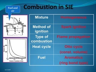
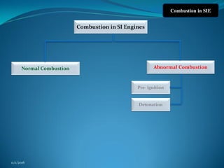
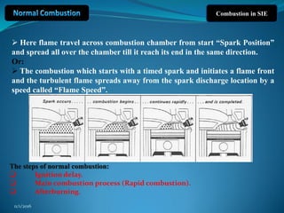
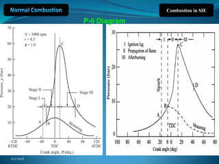
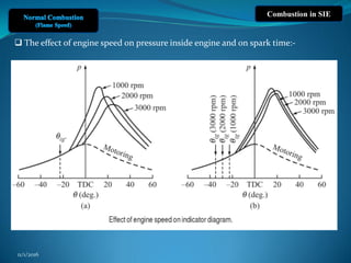
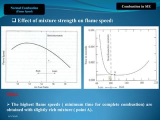
SlideShare a Scribd company logo
Lecture 4
Combustion In Internal Combustion
Engines
11/1/2016
Combustion in SIE
Mixture Homogeneous
Method of
ignition
Spark ignition
Type of
combustion
Flame propagation
Heat cycle Otto cycle
(const. volume)
Fuel Aromatics
(ring bond type)
Fuel and
air
11/1/2016
Combustion in SI Engines
Abnormal Combustion
Pre- ignition
Normal Combustion
Detonation
Combustion in SIE
11/1/2016
Combustion in SIE
11/1/2016
Combustion in SIE
 Here flame travel across combustion chamber from start “Spark Position”
and spread all over the chamber till it reach its end in the same direction.
Or:
 The combustion which starts with a timed spark and initiates a flame front
and the turbulent flame spreads away from the spark discharge location by a
speed called “Flame Speed”.
The steps of normal combustion:
 Ignition delay.
 Main combustion process (Rapid combustion).
 Afterburning.
11/1/2016
11/1/2016
Combustion in SIE
P-q Diagram
Combustion in SIE
1st Stage : Ignition Delay: (Constant time)(1.5:2 msec)
The first stage (A-B) corresponds to the time for the formation
of the self propagating nucleus of the flame.
It is a chemical process depends on:
 The nature of fuel,
 The temperature and pressure of the fuel/air mixture,
 The concentration of residuals ,
 The chemical reaction rate.
 It is also influenced by local turbulence.
11/1/2016
Combustion in SIE
2nd Stage: Main combustion process (Rapid combustion).
(Constant crank angle)
The propagation of the flame throughout the combustion chamber. It is a
chemical-physical process depends on:
Chemical composition
Temperature and pressure
Degree of turbulence
3rd Stage: Afterburning.
 The chemical reactions when the flame front reaches
the cylinder walls specially when the mixture is not
completely homogeneous, cause the temperature to
rise to a point of maximum at (G) following the point
of pressure maximum at (c).
 This stage resembles the ignition delay period
because it depends mainly on the rate of chemical
reaction not the turbulence.
11/1/2016
Combustion in SIE
Note:-
 Maximum work and power of the cycle can be obtained when the second
stage of combustion begins and ends symmetrically with respect to TDC .
 This can be achieved by adjusting the ignition timing.
11/1/2016
11/1/2016
The turbulent flame spreads away from the spark discharge location
by a speed called “ Flame Speed”.
Combustion in SIE
 Effect of flame speed on cylinder pressure:-
11/1/2016
Combustion in SIE
 Flame speed vs fuel type:-
Fuel Max. flame speed
(cm/s)
Methane, CH4 37.3
Ethane, C2H6 44.2
Propane, C3H8 42.7
Hydrogen, H2 291.2
Carbon Monoxide, CO 42.9
 Adiabatic flame temperature vs. flame speed:-
 The temperature the products of combustion will reach
if there is no heat loss from the flame zone
11/1/2016
Combustion in SIE
Factors affecting on Flame Speed:-
11/1/2016
1. Load:
 By throttling, The initial pressure and the pressure at the point of ignition
decrease and the residual gas in the mixture increase. The first phase of
combustion prolongs and the combustion process loses its stability and
frequently can not be resumed in some cycles, causing cyclic variations. To
overcome this difficulty to some extent, a rich mixture is used which may
ensure proper combustion, but the combustion process may continue during a
substantial portion of the expansion stroke.
In part load the combustion of fuel in the spark ignition engine is poor,
causing a large amount of products of incomplete combustion in the exhaust
including carbon monoxide, oxides of nitrogen and hydrocarbons which are
responsible for air pollution. Part load combustion is improved by using a rich
mixture but it causes wastage of fuel.
 When the load is reduced, the power of an engine is reduced.
Combustion in SIE
2. Turbulence:
 The turbulence helps in mixing and accelerates chemical reaction, this is
mainly due to increasing the surface area of the flame which leads to
increasing in the rate of reaction.
 The flame speed increases with increasing turbulence.
3. Engine Speed:
 when engine speed increases, flame
speed increases due to turbulence,
swirl, squish and tumble.
 The flame speed increases almost
linearly with the engine speed.
11/1/2016
11/1/2016
Combustion in SIE
 The effect of engine speed on pressure inside engine and on spark time:-
Combustion in SIE
4. Compression ratio (rc ):
 A higher compression ratio increases the pressure and temperature of the
working mixture inside the cylinder.
 Increased compression ratio reduced the clearance volume and therefore
increases the density of the cylinder gases during burning. This increases the peak
pressure and temperature and the total combustion duration decreases.
For engine have higher compression ratio, have higher flame speed.
For engine have higher compression ratio, less advance of ignition is required.
11/1/2016
Combustion in SIE
5. Inlet temperature and pressure:
 A higher initial pressure and temperature may help to form homogenous air and fuel
mixture which helps in increasing the flame speed. This is possible because of an overall
increase in the density of the charge.
flame speed increases with an increase in intake temperature and pressure.
6. Mixture ratio:
 the A/F ratio has a very significant influence on the flame speed. The highest flame
speed (minimum time for complete combustion) are obtained with richer mixture and
the lowest flame speed (maximum time for complete combustion) are obtained with
leaner mixture.
This sketch shows the relation between the mixture ratio and flame speed. You can
conclude that in leaner or richer mixture, the flame speed decreases. When the mixture
is lean or very rich , the combustion is incomplete because of less thermal energy which
resulting in lower flame speed
11/1/2016
Combustion in SIE
 Effect of mixture strength on flame speed:
Note:-
 The highest flame speeds ( minimum time for complete combustion) are
obtained with slightly rich mixture ( point A).
11/1/2016
11/1/2016
Combustion in SIE
Combustion in SIE
11/1/2016
7. Spark time:-
 the spark time has adjust direct effect on flame speed and it should be
before TDC (due to the ignition lag) to obtain maximum power.
The optimum angle of advance allows combustion to cease just after TDC, so
that maximum possible pressure is built at a point just at the beginning of
expansion stroke. This is shown as the normal curve, indicating smooth engine
running.
 Spark advance: lead to increase the peak pressure and temperature and it
make good combustion. So that Spark Advance -------- lead to High flame
speed .
 Spark retard: lead to decrease the peak pressure and temperature and it
make bad combustion. So that Spark Retard -------- lead to Low flame speed.
Combustion in SIE
11/1/2016
11/1/2016
11/1/2016

More Related Content

Similar to Lec . 4 (Normal Combustion in SIE) .pdf

Combustion in si engine
Combustion in si engineCombustion in si engine
Combustion in si engine
Sujit Regmi
 
Hot surface ignition of combustible fuels
Hot surface ignition of combustible fuelsHot surface ignition of combustible fuels
Hot surface ignition of combustible fuels
Dhaval Shiyani
 

Similar to Lec . 4 (Normal Combustion in SIE) .pdf (20)

Combustion in si engine
Combustion in si engineCombustion in si engine
Combustion in si engine
 
Combustion SI Engines - Unit-III
Combustion SI Engines - Unit-IIICombustion SI Engines - Unit-III
Combustion SI Engines - Unit-III
 
combustionsienginesslideshare-180201093555 (1).pdf
combustionsienginesslideshare-180201093555 (1).pdfcombustionsienginesslideshare-180201093555 (1).pdf
combustionsienginesslideshare-180201093555 (1).pdf
 
Combustion in Internal Combustion (IC) Engines
Combustion in Internal Combustion (IC) EnginesCombustion in Internal Combustion (IC) Engines
Combustion in Internal Combustion (IC) Engines
 
Combustion in si engine
Combustion in si engineCombustion in si engine
Combustion in si engine
 
AICE- UNIT-1.pptx
AICE- UNIT-1.pptxAICE- UNIT-1.pptx
AICE- UNIT-1.pptx
 
_engine cycles.pptx
_engine  cycles.pptx_engine  cycles.pptx
_engine cycles.pptx
 
Stratified-charge-engine-ppt
Stratified-charge-engine-pptStratified-charge-engine-ppt
Stratified-charge-engine-ppt
 
Ci engine combustion by Akhileshwar Nirala
Ci engine combustion by Akhileshwar NiralaCi engine combustion by Akhileshwar Nirala
Ci engine combustion by Akhileshwar Nirala
 
ICE Combustion PPT ICE Education-Academics
ICE Combustion PPT ICE Education-AcademicsICE Combustion PPT ICE Education-Academics
ICE Combustion PPT ICE Education-Academics
 
DJA3032 CHAPTER 3
DJA3032   CHAPTER 3DJA3032   CHAPTER 3
DJA3032 CHAPTER 3
 
Flame Stability
Flame StabilityFlame Stability
Flame Stability
 
chapter 2 INTRODUCTION TO COMBUSTION IN CI ENGINE.pptx
chapter 2 INTRODUCTION TO COMBUSTION IN CI ENGINE.pptxchapter 2 INTRODUCTION TO COMBUSTION IN CI ENGINE.pptx
chapter 2 INTRODUCTION TO COMBUSTION IN CI ENGINE.pptx
 
Detonation- by ejaz.pptx
Detonation- by ejaz.pptxDetonation- by ejaz.pptx
Detonation- by ejaz.pptx
 
Actual cycles of IC engines
Actual cycles of IC enginesActual cycles of IC engines
Actual cycles of IC engines
 
Ijmet 10 02_001
Ijmet 10 02_001Ijmet 10 02_001
Ijmet 10 02_001
 
Combustion Process in CI engine
Combustion Process in CI engineCombustion Process in CI engine
Combustion Process in CI engine
 
Hot surface ignition of combustible fuels
Hot surface ignition of combustible fuelsHot surface ignition of combustible fuels
Hot surface ignition of combustible fuels
 
A COMPREHENSIVE REVIEW ON COMBUSTION OF COMPRESSION IGNITION ENGINES USING BI...
A COMPREHENSIVE REVIEW ON COMBUSTION OF COMPRESSION IGNITION ENGINES USING BI...A COMPREHENSIVE REVIEW ON COMBUSTION OF COMPRESSION IGNITION ENGINES USING BI...
A COMPREHENSIVE REVIEW ON COMBUSTION OF COMPRESSION IGNITION ENGINES USING BI...
 
Recent Trends In IC Engines
Recent Trends In IC EnginesRecent Trends In IC Engines
Recent Trends In IC Engines
 

Recently uploaded

School management system project report.pdf
School management system project report.pdfSchool management system project report.pdf
School management system project report.pdf
Kamal Acharya
 
RS Khurmi Machine Design Clutch and Brake Exercise Numerical Solutions
RS Khurmi Machine Design Clutch and Brake Exercise Numerical SolutionsRS Khurmi Machine Design Clutch and Brake Exercise Numerical Solutions
RS Khurmi Machine Design Clutch and Brake Exercise Numerical Solutions
Atif Razi
 
Laundry management system project report.pdf
Laundry management system project report.pdfLaundry management system project report.pdf
Laundry management system project report.pdf
Kamal Acharya
 

Recently uploaded (20)

Natalia Rutkowska - BIM School Course in Kraków
Natalia Rutkowska - BIM School Course in KrakówNatalia Rutkowska - BIM School Course in Kraków
Natalia Rutkowska - BIM School Course in Kraków
 
İTÜ CAD and Reverse Engineering Workshop
İTÜ CAD and Reverse Engineering WorkshopİTÜ CAD and Reverse Engineering Workshop
İTÜ CAD and Reverse Engineering Workshop
 
ENERGY STORAGE DEVICES INTRODUCTION UNIT-I
ENERGY STORAGE DEVICES  INTRODUCTION UNIT-IENERGY STORAGE DEVICES  INTRODUCTION UNIT-I
ENERGY STORAGE DEVICES INTRODUCTION UNIT-I
 
Quality defects in TMT Bars, Possible causes and Potential Solutions.
Quality defects in TMT Bars, Possible causes and Potential Solutions.Quality defects in TMT Bars, Possible causes and Potential Solutions.
Quality defects in TMT Bars, Possible causes and Potential Solutions.
 
KIT-601 Lecture Notes-UNIT-4.pdf Frequent Itemsets and Clustering
KIT-601 Lecture Notes-UNIT-4.pdf Frequent Itemsets and ClusteringKIT-601 Lecture Notes-UNIT-4.pdf Frequent Itemsets and Clustering
KIT-601 Lecture Notes-UNIT-4.pdf Frequent Itemsets and Clustering
 
Pharmacy management system project report..pdf
Pharmacy management system project report..pdfPharmacy management system project report..pdf
Pharmacy management system project report..pdf
 
Introduction to Casting Processes in Manufacturing
Introduction to Casting Processes in ManufacturingIntroduction to Casting Processes in Manufacturing
Introduction to Casting Processes in Manufacturing
 
RESORT MANAGEMENT AND RESERVATION SYSTEM PROJECT REPORT.pdf
RESORT MANAGEMENT AND RESERVATION SYSTEM PROJECT REPORT.pdfRESORT MANAGEMENT AND RESERVATION SYSTEM PROJECT REPORT.pdf
RESORT MANAGEMENT AND RESERVATION SYSTEM PROJECT REPORT.pdf
 
Democratizing Fuzzing at Scale by Abhishek Arya
Democratizing Fuzzing at Scale by Abhishek AryaDemocratizing Fuzzing at Scale by Abhishek Arya
Democratizing Fuzzing at Scale by Abhishek Arya
 
Cloud-Computing_CSE311_Computer-Networking CSE GUB BD - Shahidul.pptx
Cloud-Computing_CSE311_Computer-Networking CSE GUB BD - Shahidul.pptxCloud-Computing_CSE311_Computer-Networking CSE GUB BD - Shahidul.pptx
Cloud-Computing_CSE311_Computer-Networking CSE GUB BD - Shahidul.pptx
 
Courier management system project report.pdf
Courier management system project report.pdfCourier management system project report.pdf
Courier management system project report.pdf
 
School management system project report.pdf
School management system project report.pdfSchool management system project report.pdf
School management system project report.pdf
 
Introduction to Machine Learning Unit-5 Notes for II-II Mechanical Engineering
Introduction to Machine Learning Unit-5 Notes for II-II Mechanical EngineeringIntroduction to Machine Learning Unit-5 Notes for II-II Mechanical Engineering
Introduction to Machine Learning Unit-5 Notes for II-II Mechanical Engineering
 
RS Khurmi Machine Design Clutch and Brake Exercise Numerical Solutions
RS Khurmi Machine Design Clutch and Brake Exercise Numerical SolutionsRS Khurmi Machine Design Clutch and Brake Exercise Numerical Solutions
RS Khurmi Machine Design Clutch and Brake Exercise Numerical Solutions
 
Scaling in conventional MOSFET for constant electric field and constant voltage
Scaling in conventional MOSFET for constant electric field and constant voltageScaling in conventional MOSFET for constant electric field and constant voltage
Scaling in conventional MOSFET for constant electric field and constant voltage
 
Peek implant persentation - Copy (1).pdf
Peek implant persentation - Copy (1).pdfPeek implant persentation - Copy (1).pdf
Peek implant persentation - Copy (1).pdf
 
NO1 Pandit Amil Baba In Bahawalpur, Sargodha, Sialkot, Sheikhupura, Rahim Yar...
NO1 Pandit Amil Baba In Bahawalpur, Sargodha, Sialkot, Sheikhupura, Rahim Yar...NO1 Pandit Amil Baba In Bahawalpur, Sargodha, Sialkot, Sheikhupura, Rahim Yar...
NO1 Pandit Amil Baba In Bahawalpur, Sargodha, Sialkot, Sheikhupura, Rahim Yar...
 
Explosives Industry manufacturing process.pdf
Explosives Industry manufacturing process.pdfExplosives Industry manufacturing process.pdf
Explosives Industry manufacturing process.pdf
 
Laundry management system project report.pdf
Laundry management system project report.pdfLaundry management system project report.pdf
Laundry management system project report.pdf
 
Event Management System Vb Net Project Report.pdf
Event Management System Vb Net  Project Report.pdfEvent Management System Vb Net  Project Report.pdf
Event Management System Vb Net Project Report.pdf
 

Lec . 4 (Normal Combustion in SIE) .pdf

  • 1. Lecture 4 Combustion In Internal Combustion Engines 11/1/2016
  • 2. Combustion in SIE Mixture Homogeneous Method of ignition Spark ignition Type of combustion Flame propagation Heat cycle Otto cycle (const. volume) Fuel Aromatics (ring bond type) Fuel and air 11/1/2016
  • 3. Combustion in SI Engines Abnormal Combustion Pre- ignition Normal Combustion Detonation Combustion in SIE 11/1/2016
  • 5. Combustion in SIE  Here flame travel across combustion chamber from start “Spark Position” and spread all over the chamber till it reach its end in the same direction. Or:  The combustion which starts with a timed spark and initiates a flame front and the turbulent flame spreads away from the spark discharge location by a speed called “Flame Speed”. The steps of normal combustion:  Ignition delay.  Main combustion process (Rapid combustion).  Afterburning. 11/1/2016
  • 7. Combustion in SIE 1st Stage : Ignition Delay: (Constant time)(1.5:2 msec) The first stage (A-B) corresponds to the time for the formation of the self propagating nucleus of the flame. It is a chemical process depends on:  The nature of fuel,  The temperature and pressure of the fuel/air mixture,  The concentration of residuals ,  The chemical reaction rate.  It is also influenced by local turbulence. 11/1/2016
  • 8. Combustion in SIE 2nd Stage: Main combustion process (Rapid combustion). (Constant crank angle) The propagation of the flame throughout the combustion chamber. It is a chemical-physical process depends on: Chemical composition Temperature and pressure Degree of turbulence 3rd Stage: Afterburning.  The chemical reactions when the flame front reaches the cylinder walls specially when the mixture is not completely homogeneous, cause the temperature to rise to a point of maximum at (G) following the point of pressure maximum at (c).  This stage resembles the ignition delay period because it depends mainly on the rate of chemical reaction not the turbulence. 11/1/2016
  • 9. Combustion in SIE Note:-  Maximum work and power of the cycle can be obtained when the second stage of combustion begins and ends symmetrically with respect to TDC .  This can be achieved by adjusting the ignition timing. 11/1/2016
  • 11. The turbulent flame spreads away from the spark discharge location by a speed called “ Flame Speed”. Combustion in SIE  Effect of flame speed on cylinder pressure:- 11/1/2016
  • 12. Combustion in SIE  Flame speed vs fuel type:- Fuel Max. flame speed (cm/s) Methane, CH4 37.3 Ethane, C2H6 44.2 Propane, C3H8 42.7 Hydrogen, H2 291.2 Carbon Monoxide, CO 42.9  Adiabatic flame temperature vs. flame speed:-  The temperature the products of combustion will reach if there is no heat loss from the flame zone 11/1/2016
  • 13. Combustion in SIE Factors affecting on Flame Speed:- 11/1/2016 1. Load:  By throttling, The initial pressure and the pressure at the point of ignition decrease and the residual gas in the mixture increase. The first phase of combustion prolongs and the combustion process loses its stability and frequently can not be resumed in some cycles, causing cyclic variations. To overcome this difficulty to some extent, a rich mixture is used which may ensure proper combustion, but the combustion process may continue during a substantial portion of the expansion stroke. In part load the combustion of fuel in the spark ignition engine is poor, causing a large amount of products of incomplete combustion in the exhaust including carbon monoxide, oxides of nitrogen and hydrocarbons which are responsible for air pollution. Part load combustion is improved by using a rich mixture but it causes wastage of fuel.  When the load is reduced, the power of an engine is reduced.
  • 14. Combustion in SIE 2. Turbulence:  The turbulence helps in mixing and accelerates chemical reaction, this is mainly due to increasing the surface area of the flame which leads to increasing in the rate of reaction.  The flame speed increases with increasing turbulence. 3. Engine Speed:  when engine speed increases, flame speed increases due to turbulence, swirl, squish and tumble.  The flame speed increases almost linearly with the engine speed. 11/1/2016
  • 15. 11/1/2016 Combustion in SIE  The effect of engine speed on pressure inside engine and on spark time:-
  • 16. Combustion in SIE 4. Compression ratio (rc ):  A higher compression ratio increases the pressure and temperature of the working mixture inside the cylinder.  Increased compression ratio reduced the clearance volume and therefore increases the density of the cylinder gases during burning. This increases the peak pressure and temperature and the total combustion duration decreases. For engine have higher compression ratio, have higher flame speed. For engine have higher compression ratio, less advance of ignition is required. 11/1/2016
  • 17. Combustion in SIE 5. Inlet temperature and pressure:  A higher initial pressure and temperature may help to form homogenous air and fuel mixture which helps in increasing the flame speed. This is possible because of an overall increase in the density of the charge. flame speed increases with an increase in intake temperature and pressure. 6. Mixture ratio:  the A/F ratio has a very significant influence on the flame speed. The highest flame speed (minimum time for complete combustion) are obtained with richer mixture and the lowest flame speed (maximum time for complete combustion) are obtained with leaner mixture. This sketch shows the relation between the mixture ratio and flame speed. You can conclude that in leaner or richer mixture, the flame speed decreases. When the mixture is lean or very rich , the combustion is incomplete because of less thermal energy which resulting in lower flame speed 11/1/2016
  • 18. Combustion in SIE  Effect of mixture strength on flame speed: Note:-  The highest flame speeds ( minimum time for complete combustion) are obtained with slightly rich mixture ( point A). 11/1/2016
  • 20. Combustion in SIE 11/1/2016 7. Spark time:-  the spark time has adjust direct effect on flame speed and it should be before TDC (due to the ignition lag) to obtain maximum power. The optimum angle of advance allows combustion to cease just after TDC, so that maximum possible pressure is built at a point just at the beginning of expansion stroke. This is shown as the normal curve, indicating smooth engine running.  Spark advance: lead to increase the peak pressure and temperature and it make good combustion. So that Spark Advance -------- lead to High flame speed .  Spark retard: lead to decrease the peak pressure and temperature and it make bad combustion. So that Spark Retard -------- lead to Low flame speed.