SlideShare a Scribd company logo
1 of 54
20ME703PE-ADVANCED IC ENGINES
UNIT I SPARK IGNITION ENGINES 9
Air-fuel ratio requirements – stages of combustion – normal and
abnormal combustion – factors affecting knock – fuel injection systems –
mono point, multipoint and direct injection combustion chambers –
effects of compression ratio – introduction to thermodynamic analysis of
combustion process.
UNIT II COMPRESSION IGNITION ENGINES 9
Stages of combustion – normal and abnormal combustion – factors
affecting knock – direct and indirect injection systems – air motion –
swirl measurement – combustion chambers – fuel spray behaviour –
spray structure and spray penetration – turbo charging – introduction to
thermodynamic analysis of combustion process.
UNIT III EMISSION FORMATION AND CONTROL 9
Formation of NOX, HC/CO mechanism – smoke and particulate emissions
– green house effect – methods of controlling emissions – three way
catalytic converter – particulate trap – emission (HC, CO, NO and NOX)
measuring equipment – smoke and particulate measurement – emission
norms – national and international emission standards.
UNIT IV ALTERNATE FUELS 9
Need for alternate fuels – alcohols, vegetable oils, bio-diesel, bio-gas,
natural gas, liquefied petroleum gas and hydrogen – manufacturing,
storage and safety properties – engine modifications and emissions –
performance, combustion and emission characteristics of SI and CI
engines.
UNIT V RECENT TRENDS 9
Homogeneous charge compression ignition engine – lean burn engine –
stratified charge engine – surface ignition engine – electronic engine
management – common rail direct injection diesel engine – gasoline
direct injection engine – hybrid electric vehicles – on board diagnostics –
variable geometry turbochargers – NOx absorbers.
UNIT-I
SPARK IGNITION ENGINES
TOPICS
Air-fuel ratio requirements – stages of combustion –
normal and abnormal combustion – factors affecting
knock – fuel injection systems – mono point,
multipoint and direct injection combustion chambers
– effects of compression ratio – introduction to
thermodynamic analysis of combustion process.
AIR-FUEL MIXTURES
An engine is generally operated at different loads and
speeds. For this, proper air-fuel mixture should be supplied to
the engine cylinder. Fuel and air are mixed to form three
different types of mixtures.
(1) Chemically Correct Mixture
(2) Rich Mixture and
(3) Lean Mixture
β€’ Chemically correct or stoichiometric mixture is one in which
there is just enough air for complete combustion of the fuel. For
example, to burn one kg of octane (CsH18) completely 15.12 kg
of air is required.
β€’ Hence chemically correct A/F ratio for C8H18 is 15.12:1;
usually approximated to 15:1. This chemically correct mixture
will vary only slightly in numerical value between different
hydrocarbon fuels. It is always computed from the chemical
equation for complete combustion for a particular fuel.
β€’ Complete combustion means all carbon in the fuel is converted
to CO2 and all hydrogen to H2O.
β€’ A mixture which contains less air than the stoichiometric
requirement is called a rich mixture (example, A/F ratio of 12:1,
10:1 etc.). A mixture which contains more air than the
stoichiometric requirement is called a lean mixture (example,
A/F ratio of 17:1, 20:1 etc.).
β€’ There is, however, a limited range of A/F ratios in a
homogeneous mixture, only within which combustion in an SI
engine will occur. Outside this range, the ratio is either too rich
or too lean to sustain flame propagation. This range of useful
A/F ratio runs from approximately 9:1 (rich) to 19:1 (lean) as
indicated in Figure.
.
β€’ The A/F ratio will affect both the power output and the brake
specific fuel consumption, as indicated by the typical curves shown
in Figure.
β€’ The mixture corresponding to the maximum output on the curve is
called the best power mixture with an A/F ratio of approximately
12:1.
β€’ The mixture corresponding to the minimum point on the bs fc curve
is called the best economy mixture. The A/F ratio is approximately
16:1.
β€’ It may be noted that the best power mixture is much richer than the
chemically correct mixture and the best economy mixture is slightly
leaner than the chemically correct.
.
β€’ Under normal conditions it is desirable to run the engine on the
maximum economy mixture, viz., around 16:1 air-fuel ratio. For
quick acceleration and for maximum power, rich mixture, viz., 12:1
air-fuel ratio is required.
Automotive Engine Air-Fuel Mixture Requirements
β€’ Actual air-fuel mixture requirements in an automotive engine vary
considerably from the ideal conditions discussed in the previous
section. For successful operation of the engine, the carburetor has to
provide mixtures which follow the general shape of the curve ABCD
(single cylinder) and A'B'C'D' (multicylinder) in Figure.
β€’ which represents a typical automotive engine requirement. The
carburetor must be suitably designed to meet the various engine
requirements.
(i) Idling (mixture must be enriched)
(ii) Cruising (mixture must be leaned)
(iii) High Power (mixture must be enriched)
THROTTLE OPERATION
STAGES OF COMBUSTION IN SI ENGINES
β€’ A typical theoretical pressure-crank angle diagram, during the process
of compression (a-b), combustion (b-c) and expansion (c-d) in an
ideal four-stroke spark ignition engine is shown in Figure.
β€’ In an ideal engine, as can be seen from the diagram, the entire
pressure rise during combustion takes place at constant volume i.e., at
TDC. However, in an actual engine this does not happen. The detailed
process of combustion in an actual SI engine is described below. Sir
Ricardo, known as the father of engine research, describes the
combustion process in a SI engine as consisting of three stages
Theoretical P-Ι΅ Diagram
β€’ The first stage (A-B) is referred to as the ignition lag or
preparation phase in which growth and development of a self
propagating nucleus of flame takes place. This is a chemical
process depending upon both temperature and pressure, the
nature of the fuel and the proportion of the exhaust residual gas.
Further, it also depends upon the relationship between the
temperature and the rate of reaction.
β€’ The second stage (B-C) is a physical one and it is concerned
with the spread of the flame throughout the combustion
chamber. The starting point of the second stage is where the
first measurable rise of pressure is seen on the indicator diagram
ie, the point where the line of combustion departs from the
compression line (point B). This can be seen from the deviation
from the motoring curve.
β€’ During the second damage the flame propagates practically at a
constant with Heat transfer to the cylinder wall is low, because
only a small part of the burning mixture comes in contact with
the cylinder wall during this period.
β€’ The rate of heat release depends largely on the turbulence
Intensity and also on the reaction rate which is dependent on the
mixture composition. The rate of pressure rise is proportional to
the rate of heat release because during this stage, the
combustion chamber volume remains practically constant (since
piston is near the top dead centre).
β€’ The starting point of the third stage is usually taken as the
instant at which the maximum pressure is reached on the
indicator diagram (point C). The flame velocity decreases
during this stage. The rate of combustion becomes low due to
lower flame velocity and reduced flame front surface. Since the
expansion stroke starts before this stage of combustion, with the
piston moving away from the top dead centre, there can be no
pressure rise during this stage.
STAGES OF COMBUSTION IN SI ENGINE
FACTORS INFLUENCING THE FLAME
SPEED
β€’ Turbulence
β€’ Fuel-Air Ratio
β€’ Temperature and Pressure
β€’ Compression Ratio
β€’ Engine Output
β€’ Engine Size
β€’ NORMAL COMBUSTION: In the normal combustion in S.I
engine, the flame is started by the ignition of spark which
travels across the combustion chamber gradually and runs the
engine smoothly.
β€’ ABNORMAL COMBUSTION: In normal combustion, the
flame initiated by the spark travels across the combustion
chamber in a fairly uniform manner. Under certain operating
conditions the combustion deviates from its normal course
leading to loss of performance and possible damage to the
engine. This type of combustion may be termed as an
abnormal combustion or knocking combustion. The
consequences of this abnormal combustion process are the loss
of power recurring pre-ignition and mechanical damage to the
engine.
KNOCK IN SI ENGINES
β€’In a spark-ignition engine combustion which is initiated between the
spark plug electrodes spreads across the combustible mixture. A
definite flame front which separates the fresh mixture from the
products of combustion travels from the spark plug to the other end
of the combustion chamber.
β€’Heat-release due to combustion increases the temperature and
consequently the pressure, of the burned part of the mixture above
those of the unburned mixture. In order to effect pressure
equalization the burned part of the mixture will expand, and
compress the unburned mixture adiabatically thereby increasing its
pressure and temperature.
β€’ This process continues as the flame front advances through the
mixture and the temperature and pressure of the unburned
mixture are increased further.
β€’ If the temperature of the unburnt mixture exceeds the self-
ignition temperature of the fuel and remains at or above this
temperature during the period of preflame reactions (ignition
lag), spontaneous ignition or auto ignition occurs at various
pin-point locations. This phenomenon is called knocking. The
process of auto ignition leads towards engine knock.
Normal Vs Abnormal Combustion in SI
Engine
Knock Limited Parameters
It should be the aim of the designer to reduce the tendency
of knocking in the engine. In this connection, certain knock
limited parameters are explained.
β€’ Knock Limited Compression Ratio: The knock limited
compression ratio is obtained by increasing the compression
ratio on a variable compression ratio engine until incipient
knocking is observed. Any change in operating conditions
such as fuel-air ratio or in the engine design that increases the
knock limited compression ratio is said to reduce the tendency
towards knocking.
β€’ Knock Limited Inlet Pressure: The inlet pressure can be
increased by opening the throttle or increasing supercharger
delivery pressure until incipient knock is observed. An
increase in knock limited inlet pressure indicates a reduction in
the knocking tendency.
β€’ Knock Limited Indicated Mean Effective Pressure: The
indicated mean effective pressure measured at incipient knock
is usually abbreviated as Klimep. This parameter and the
corresponding fuel consumption are obviously of great
practical interest. An useful measure of knocking tendency
called the performance number, has been developed from the
concept of knock limited indicated mean effective pressure.
EFFECT OF ENGINE VARIABLES ON KNOCK
From the discussion on knock in the previous section, it may be
seen that four major factors are involved in either producing or
preventing knock. These are the temperature, pressure, density of the
unburned charge and the time factors. Since, the effect of
temperature, pressure and density are closely interrelated, these three
are consolidated into one group and the time factors into another
group
Density Factors:
Any factor in the design or operation of an engine which
tends to reduce the temperature of the unburned charge should
reduce the possibility of knocking by reducing the temperature
of the end charge for auto ignition. Similarly, any factor which
reduces the density of the charge tends to reduce knocking by
providing lower energy release. Further, the effect of the
following parameters which are directly or indirectly
connected with temperature, pressure and density factors on
the possibility of knocking is discussed below.
Compression Ratio :
Compression ratio of an engine is an important factor which
determines both the pressure and temperature at the beginning of
the combustion process. Increase in compression ratio increases
the pressure and temperature of the gases at the end of the
compression stroke This decreases the ignition lag of the end gas
and thereby increasing the tendency for knocking. The overall
increase in the density of the charge due to higher compression
ratio increases the preflame reactions in the end charge thereby
increasing the knocking tendency of the engine. The in- in the
knocking tendency of the engine with increasing compression
ratio is the main reason for limiting the compression ratio to a
lower value.
Mass of Inducted Charge:
A reduction in the mass of the inducted large into the cylinder of
an engine by throttling or by reducing the mount of supercharging
reduces both temperature and density of the charge at the time of
ignition. This decreases the tendency of knocking.
Inlet Temperature of the Mixture:
Increase in the inlet temperature of the mixture makes the compression
temperature higher thereby, increasing the tendency of knocking.
Further, volumetric efficiency will be lowered. Hence, a lower inlet
temperature is always preferable to reduce knocking. It important that
the temperature should not be so low as to cause starting and
vaporization problems in the engine.
Temperature of the Combustion Chamber Walls:
Temperature of the combustion chamber walls play a predominant
role in knocking. In order to prevent knocking the hot spots in the
combustion chamber should be avoided. Since, the spark plug and
exhaust valve are two hottest parts in the combustion chamber, the
end gas shou should not be compressed against them
Retarding the Spark Timing:
By retarding the spark timing from the optimized timing, ie,
having the spark closer to TDC. the peak pressures are reached
farther down on the power stroke and are thus of lower magnitude.
This might reduce the knocking. ld not be compressed against
them.
Power Output of the Engine:
A decrease in the output of the engine decreases the temperature of
the cylinder and the combustion chamber walls and also the
pressure of the charge thereby lowering mixture and end gas
temperatures. This reduces the tendency to knock.
Time Factors:
Increasing the flame speed or increasing the duration of the ignition
lag or reducing the time of exposure of the unburned mixture to
auto ignition condition will tend to reduce knocking. The
following factors, in most cases reduce the possibility of
knocking.
Turbulence:
Turbulence depends on the design of the combustion chamber and
on engine speed. Increasing turbulence increases the flame speed
and reduces the time available for the end charge to attain
autoignition conditions thereby decreasing the tendency to knock.
Engine Speed:
An increase in engine speed increases the turbulence o the mixture
considerably resulting in increased flame speed, and reduces the
time available for preflame reactions. Hence knocking tendency is
reduce at higher speeds.
Flame Travel Distance:
The knocking tendency is reduced by shortening the time required
for the flame front to traverse the combustion chamber. Engine
size and spark plug position are the three important factors
governing the fame travel distance.
Engine Size:
The flame requires a longer time to travel across the combustion
chamber of a larger engine. Therefore, a larger engine has a
greater tendency knocking than a mater engine since there is more
time for the end gas to autoignite. Hence, and SI engine is
generally limited to size of about 150 mm bore.
Typical Combustion Chamber
The design of the combustion chamber for an SI engine has an
important influence on the engine performance and its knocking
tendencies. The design involves the shape of the combustion chamber,
the location of spark plug and the location of inlet and exhaust valves.
Because of this importance, the combustion chamber design has been
a subject of considerable amount of research and development in the
last fifty years. It has resulted in the raising of the compression ratio
of the engine from 4 before the first world
war period to 11 in the present times with special combustion
chamber designs and suitable antiknock fuels. The important
requirements of an SI engine combustion chamber are to provide
high power output with minimum octane requirement, high thermal
efficiency and smooth engine operation. Combustion chambers
must be designed carefully, keeping in mind the following general
objectives.
β€’ Smooth Engine Operation
β€’ Moderate Rate of Pressure Rise
β€’ Reducing the Possibility of Knocking
β€’ High Power Output and Thermal Efficiency
TYPES OF INJECTION SYSTEMS IN SI
ENGINE
INDIRECT FUEL
INJECTION SYSTEM
(manifold injection system)
GASOLINE DIRECT FUEL
INJECTION SYSTEM
Single Point Fuel
Injection System
Multi Point Fuel
Injection System
2. Port Injection
1. Throttle body
injection
1. Throttle body
injection
2. Port Injection
CONTINUOUS INJECTION SYSTEMS
This system usually has a rotary pump. The pump
maintains a fuel line gauge pressure of about 0.75 to 1.5 bar.
The system injects the fuel through a nozzle located in the
manifold immediately downstream of the throttle plate. In a
supercharged engine, fuel is injected at the entrance of the
supercharger. The timing and duration of the fuel injection is
determined by Electronic Control Unit (ECU) depending upon
the load and speed.
TIMED FUEL INJECTION SYSTEM
This system has a fuel supply pump which sends fuel at a low
pressure of about 2 bar when the engine is running at maximum
speed. A fuel metering or injection pump and a nozzle are the other
parts of the system. The nozzle injects the fuel in the manifold or the
cylinder head port at about 6.5 bar or into the combustion chamber at
pressures that range from 16 to 35 bar. Timed injection system injects
fuel usually during the early part of the suction stroke. During
maximum power operation injection begins after the closure of the
exhaust valve and ends usually after BDC. Direct in-cylinder injection
is superior and always desirable and better compared to manifold
GASOLINE INJECTION IN FOUR STROKE ENGINES
Different methods of injection
Carburetor
Fuel injection is a system for mixing fuel with air in an internal
combustion engine. The functional objectives for fuel injection systems
vary but all of them share the central task of supplying fuel to the
combustion process.
MONOPOINT INJECTION
In the Multipoint Injection System, we have one injector per cylinder,
the injector injects the fuel into the admission valve which admits the
fuel and air into the cylinder. This gives an individual control on this
cylinder, improving the fuel consumption in relation of the Single point
injection.
MULTIPOINT INJECTION
THERMODYNAMIC ANALYSIS OF
COMBUSTION PROCESS
The main drawback of the Carnot cycle is its
impracticability due to high pressure and high volume ratios
employed with comparatively low mean effective pressure.
Nicolaus Otto (1876), proposed a constant-volume heat
addition cycle which forms the basis for the working of today's
spark-ignition engines. The cycle is shown on p-V and T-S
diagrams in Fig.
When the engine is working on full throttle, the processes
0-1 and 1-0 on the P-V diagram represents suction and exhaust
processes and their effect is nullified. The process 1-2
represents isentropic compression of the air when the piston
moves from bottom dead centre to top dead centre. During the
process 2-3 heat is supplied reversibly at constant volume.
This process corresponds to spark-ignition and combustion in
the actual engine. The processes 3-4 and 4-1 represent
isentropic expansion and constant volume heat rejection
respectively
OTTO CYCLE (P-V and T-S diagram)
AICE- UNIT-1.pptx
AICE- UNIT-1.pptx
AICE- UNIT-1.pptx
AICE- UNIT-1.pptx
AICE- UNIT-1.pptx
AICE- UNIT-1.pptx
AICE- UNIT-1.pptx

More Related Content

Similar to AICE- UNIT-1.pptx

IC ENGINE'S COMBUTION
IC ENGINE'S COMBUTION IC ENGINE'S COMBUTION
IC ENGINE'S COMBUTION SKD CHITS
Β 
6_CI_Engine_Combustion.ppt
6_CI_Engine_Combustion.ppt6_CI_Engine_Combustion.ppt
6_CI_Engine_Combustion.pptAnandan M
Β 
5+ combustion and combustion chamber for si engines
5+ combustion  and combustion chamber for si engines5+ combustion  and combustion chamber for si engines
5+ combustion and combustion chamber for si enginesFasilMelese
Β 
UNIT-I SPARK IGNITION ENGINES.ppt
UNIT-I SPARK IGNITION ENGINES.pptUNIT-I SPARK IGNITION ENGINES.ppt
UNIT-I SPARK IGNITION ENGINES.pptDr.G.Saravanan
Β 
Fuel air cycle
Fuel air cycleFuel air cycle
Fuel air cycleSoumith V
Β 
ICE_22_Chapter 4.v2.ppt
ICE_22_Chapter 4.v2.pptICE_22_Chapter 4.v2.ppt
ICE_22_Chapter 4.v2.pptishi67
Β 
Recent Trends In IC Engines
Recent Trends In IC EnginesRecent Trends In IC Engines
Recent Trends In IC EnginesPrasad V
Β 
gas turbine cycles.pptx .
gas turbine cycles.pptx                    .gas turbine cycles.pptx                    .
gas turbine cycles.pptx .happycocoman
Β 
Actual cycles of IC engines
Actual cycles of IC enginesActual cycles of IC engines
Actual cycles of IC enginesSoumith V
Β 
Thermal engineering 2 marks
Thermal engineering 2 marks Thermal engineering 2 marks
Thermal engineering 2 marks Shivendu Anand
Β 
ATD CI ENGINE COMBUSTION PHENOMENON UNIT-3 PPT.ppt
ATD CI ENGINE COMBUSTION PHENOMENON UNIT-3 PPT.pptATD CI ENGINE COMBUSTION PHENOMENON UNIT-3 PPT.ppt
ATD CI ENGINE COMBUSTION PHENOMENON UNIT-3 PPT.pptAryanYadav553427
Β 
ATD CI ENGINE COMBUSTION PHENOMENON UNIT-3 PPT (1).ppt
ATD CI ENGINE COMBUSTION PHENOMENON UNIT-3 PPT (1).pptATD CI ENGINE COMBUSTION PHENOMENON UNIT-3 PPT (1).ppt
ATD CI ENGINE COMBUSTION PHENOMENON UNIT-3 PPT (1).ppthodmech18
Β 
DJA3032 CHAPTER 3
DJA3032   CHAPTER 3DJA3032   CHAPTER 3
DJA3032 CHAPTER 3mechanical86
Β 
Advanced Ic engines unit 1
Advanced Ic engines unit 1Advanced Ic engines unit 1
Advanced Ic engines unit 1Ravi Rajan
Β 
compression egnition engine engine
compression egnition engine enginecompression egnition engine engine
compression egnition engine enginenaphis ahamad
Β 
mcl345-40.ppt
mcl345-40.pptmcl345-40.ppt
mcl345-40.pptssuser10ff2e
Β 

Similar to AICE- UNIT-1.pptx (20)

IC ENGINE'S COMBUTION
IC ENGINE'S COMBUTION IC ENGINE'S COMBUTION
IC ENGINE'S COMBUTION
Β 
6_CI_Engine_Combustion.ppt
6_CI_Engine_Combustion.ppt6_CI_Engine_Combustion.ppt
6_CI_Engine_Combustion.ppt
Β 
CI engine
CI engineCI engine
CI engine
Β 
mel713-32.ppt
mel713-32.pptmel713-32.ppt
mel713-32.ppt
Β 
Combustion in CI engines
Combustion in CI enginesCombustion in CI engines
Combustion in CI engines
Β 
5+ combustion and combustion chamber for si engines
5+ combustion  and combustion chamber for si engines5+ combustion  and combustion chamber for si engines
5+ combustion and combustion chamber for si engines
Β 
UNIT-I SPARK IGNITION ENGINES.ppt
UNIT-I SPARK IGNITION ENGINES.pptUNIT-I SPARK IGNITION ENGINES.ppt
UNIT-I SPARK IGNITION ENGINES.ppt
Β 
Fuel air cycle
Fuel air cycleFuel air cycle
Fuel air cycle
Β 
ICE_22_Chapter 4.v2.ppt
ICE_22_Chapter 4.v2.pptICE_22_Chapter 4.v2.ppt
ICE_22_Chapter 4.v2.ppt
Β 
Recent Trends In IC Engines
Recent Trends In IC EnginesRecent Trends In IC Engines
Recent Trends In IC Engines
Β 
gas turbine cycles.pptx .
gas turbine cycles.pptx                    .gas turbine cycles.pptx                    .
gas turbine cycles.pptx .
Β 
Actual cycles of IC engines
Actual cycles of IC enginesActual cycles of IC engines
Actual cycles of IC engines
Β 
Thermal engineering 2 marks
Thermal engineering 2 marks Thermal engineering 2 marks
Thermal engineering 2 marks
Β 
ATD CI ENGINE COMBUSTION PHENOMENON UNIT-3 PPT.ppt
ATD CI ENGINE COMBUSTION PHENOMENON UNIT-3 PPT.pptATD CI ENGINE COMBUSTION PHENOMENON UNIT-3 PPT.ppt
ATD CI ENGINE COMBUSTION PHENOMENON UNIT-3 PPT.ppt
Β 
ATD CI ENGINE COMBUSTION PHENOMENON UNIT-3 PPT (1).ppt
ATD CI ENGINE COMBUSTION PHENOMENON UNIT-3 PPT (1).pptATD CI ENGINE COMBUSTION PHENOMENON UNIT-3 PPT (1).ppt
ATD CI ENGINE COMBUSTION PHENOMENON UNIT-3 PPT (1).ppt
Β 
Combustion
CombustionCombustion
Combustion
Β 
DJA3032 CHAPTER 3
DJA3032   CHAPTER 3DJA3032   CHAPTER 3
DJA3032 CHAPTER 3
Β 
Advanced Ic engines unit 1
Advanced Ic engines unit 1Advanced Ic engines unit 1
Advanced Ic engines unit 1
Β 
compression egnition engine engine
compression egnition engine enginecompression egnition engine engine
compression egnition engine engine
Β 
mcl345-40.ppt
mcl345-40.pptmcl345-40.ppt
mcl345-40.ppt
Β 

More from GunaSekaran958261 (13)

AICE- UNIT-5.pptx
AICE- UNIT-5.pptxAICE- UNIT-5.pptx
AICE- UNIT-5.pptx
Β 
AICE- UNIT-4.pptx
AICE- UNIT-4.pptxAICE- UNIT-4.pptx
AICE- UNIT-4.pptx
Β 
AICE- UNIT-3.pptx
AICE- UNIT-3.pptxAICE- UNIT-3.pptx
AICE- UNIT-3.pptx
Β 
UCM-UNIT 5.pptx
UCM-UNIT 5.pptxUCM-UNIT 5.pptx
UCM-UNIT 5.pptx
Β 
UCM-UNIT 4.pptx
UCM-UNIT 4.pptxUCM-UNIT 4.pptx
UCM-UNIT 4.pptx
Β 
UCM-UNIT 3.pptx
UCM-UNIT 3.pptxUCM-UNIT 3.pptx
UCM-UNIT 3.pptx
Β 
UCM-UNIT 2.pptx
UCM-UNIT 2.pptxUCM-UNIT 2.pptx
UCM-UNIT 2.pptx
Β 
UCM-UNIT- 1.pptx
UCM-UNIT- 1.pptxUCM-UNIT- 1.pptx
UCM-UNIT- 1.pptx
Β 
MM-UNIT-V.pptx
MM-UNIT-V.pptxMM-UNIT-V.pptx
MM-UNIT-V.pptx
Β 
MM-UNIT-IV.pptx
MM-UNIT-IV.pptxMM-UNIT-IV.pptx
MM-UNIT-IV.pptx
Β 
MM-UNIT-III.pptx
MM-UNIT-III.pptxMM-UNIT-III.pptx
MM-UNIT-III.pptx
Β 
MM-UNIT-II.pptx
MM-UNIT-II.pptxMM-UNIT-II.pptx
MM-UNIT-II.pptx
Β 
MM-UNIT-I.pptx
MM-UNIT-I.pptxMM-UNIT-I.pptx
MM-UNIT-I.pptx
Β 

Recently uploaded

main PPT.pptx of girls hostel security using rfid
main PPT.pptx of girls hostel security using rfidmain PPT.pptx of girls hostel security using rfid
main PPT.pptx of girls hostel security using rfidNikhilNagaraju
Β 
Electronically Controlled suspensions system .pdf
Electronically Controlled suspensions system .pdfElectronically Controlled suspensions system .pdf
Electronically Controlled suspensions system .pdfme23b1001
Β 
CCS355 Neural Network & Deep Learning UNIT III notes and Question bank .pdf
CCS355 Neural Network & Deep Learning UNIT III notes and Question bank .pdfCCS355 Neural Network & Deep Learning UNIT III notes and Question bank .pdf
CCS355 Neural Network & Deep Learning UNIT III notes and Question bank .pdfAsst.prof M.Gokilavani
Β 
Call Girls Narol 7397865700 Independent Call Girls
Call Girls Narol 7397865700 Independent Call GirlsCall Girls Narol 7397865700 Independent Call Girls
Call Girls Narol 7397865700 Independent Call Girlsssuser7cb4ff
Β 
πŸ”9953056974πŸ”!!-YOUNG call girls in Rajendra Nagar Escort rvice Shot 2000 nigh...
πŸ”9953056974πŸ”!!-YOUNG call girls in Rajendra Nagar Escort rvice Shot 2000 nigh...πŸ”9953056974πŸ”!!-YOUNG call girls in Rajendra Nagar Escort rvice Shot 2000 nigh...
πŸ”9953056974πŸ”!!-YOUNG call girls in Rajendra Nagar Escort rvice Shot 2000 nigh...9953056974 Low Rate Call Girls In Saket, Delhi NCR
Β 
Call Girls Delhi {Jodhpur} 9711199012 high profile service
Call Girls Delhi {Jodhpur} 9711199012 high profile serviceCall Girls Delhi {Jodhpur} 9711199012 high profile service
Call Girls Delhi {Jodhpur} 9711199012 high profile servicerehmti665
Β 
Introduction to Microprocesso programming and interfacing.pptx
Introduction to Microprocesso programming and interfacing.pptxIntroduction to Microprocesso programming and interfacing.pptx
Introduction to Microprocesso programming and interfacing.pptxvipinkmenon1
Β 
Sachpazis Costas: Geotechnical Engineering: A student's Perspective Introduction
Sachpazis Costas: Geotechnical Engineering: A student's Perspective IntroductionSachpazis Costas: Geotechnical Engineering: A student's Perspective Introduction
Sachpazis Costas: Geotechnical Engineering: A student's Perspective IntroductionDr.Costas Sachpazis
Β 
Concrete Mix Design - IS 10262-2019 - .pptx
Concrete Mix Design - IS 10262-2019 - .pptxConcrete Mix Design - IS 10262-2019 - .pptx
Concrete Mix Design - IS 10262-2019 - .pptxKartikeyaDwivedi3
Β 
Architect Hassan Khalil Portfolio for 2024
Architect Hassan Khalil Portfolio for 2024Architect Hassan Khalil Portfolio for 2024
Architect Hassan Khalil Portfolio for 2024hassan khalil
Β 
Call Us ≽ 8377877756 β‰Ό Call Girls In Shastri Nagar (Delhi)
Call Us ≽ 8377877756 β‰Ό Call Girls In Shastri Nagar (Delhi)Call Us ≽ 8377877756 β‰Ό Call Girls In Shastri Nagar (Delhi)
Call Us ≽ 8377877756 β‰Ό Call Girls In Shastri Nagar (Delhi)dollysharma2066
Β 
Current Transformer Drawing and GTP for MSETCL
Current Transformer Drawing and GTP for MSETCLCurrent Transformer Drawing and GTP for MSETCL
Current Transformer Drawing and GTP for MSETCLDeelipZope
Β 
VICTOR MAESTRE RAMIREZ - Planetary Defender on NASA's Double Asteroid Redirec...
VICTOR MAESTRE RAMIREZ - Planetary Defender on NASA's Double Asteroid Redirec...VICTOR MAESTRE RAMIREZ - Planetary Defender on NASA's Double Asteroid Redirec...
VICTOR MAESTRE RAMIREZ - Planetary Defender on NASA's Double Asteroid Redirec...VICTOR MAESTRE RAMIREZ
Β 
INFLUENCE OF NANOSILICA ON THE PROPERTIES OF CONCRETE
INFLUENCE OF NANOSILICA ON THE PROPERTIES OF CONCRETEINFLUENCE OF NANOSILICA ON THE PROPERTIES OF CONCRETE
INFLUENCE OF NANOSILICA ON THE PROPERTIES OF CONCRETEroselinkalist12
Β 
SPICE PARK APR2024 ( 6,793 SPICE Models )
SPICE PARK APR2024 ( 6,793 SPICE Models )SPICE PARK APR2024 ( 6,793 SPICE Models )
SPICE PARK APR2024 ( 6,793 SPICE Models )Tsuyoshi Horigome
Β 
Heart Disease Prediction using machine learning.pptx
Heart Disease Prediction using machine learning.pptxHeart Disease Prediction using machine learning.pptx
Heart Disease Prediction using machine learning.pptxPoojaBan
Β 

Recently uploaded (20)

main PPT.pptx of girls hostel security using rfid
main PPT.pptx of girls hostel security using rfidmain PPT.pptx of girls hostel security using rfid
main PPT.pptx of girls hostel security using rfid
Β 
Electronically Controlled suspensions system .pdf
Electronically Controlled suspensions system .pdfElectronically Controlled suspensions system .pdf
Electronically Controlled suspensions system .pdf
Β 
β˜… CALL US 9953330565 ( HOT Young Call Girls In Badarpur delhi NCR
β˜… CALL US 9953330565 ( HOT Young Call Girls In Badarpur delhi NCRβ˜… CALL US 9953330565 ( HOT Young Call Girls In Badarpur delhi NCR
β˜… CALL US 9953330565 ( HOT Young Call Girls In Badarpur delhi NCR
Β 
CCS355 Neural Network & Deep Learning UNIT III notes and Question bank .pdf
CCS355 Neural Network & Deep Learning UNIT III notes and Question bank .pdfCCS355 Neural Network & Deep Learning UNIT III notes and Question bank .pdf
CCS355 Neural Network & Deep Learning UNIT III notes and Question bank .pdf
Β 
Call Us -/9953056974- Call Girls In Vikaspuri-/- Delhi NCR
Call Us -/9953056974- Call Girls In Vikaspuri-/- Delhi NCRCall Us -/9953056974- Call Girls In Vikaspuri-/- Delhi NCR
Call Us -/9953056974- Call Girls In Vikaspuri-/- Delhi NCR
Β 
Call Girls Narol 7397865700 Independent Call Girls
Call Girls Narol 7397865700 Independent Call GirlsCall Girls Narol 7397865700 Independent Call Girls
Call Girls Narol 7397865700 Independent Call Girls
Β 
young call girls in Green ParkπŸ” 9953056974 πŸ” escort Service
young call girls in Green ParkπŸ” 9953056974 πŸ” escort Serviceyoung call girls in Green ParkπŸ” 9953056974 πŸ” escort Service
young call girls in Green ParkπŸ” 9953056974 πŸ” escort Service
Β 
πŸ”9953056974πŸ”!!-YOUNG call girls in Rajendra Nagar Escort rvice Shot 2000 nigh...
πŸ”9953056974πŸ”!!-YOUNG call girls in Rajendra Nagar Escort rvice Shot 2000 nigh...πŸ”9953056974πŸ”!!-YOUNG call girls in Rajendra Nagar Escort rvice Shot 2000 nigh...
πŸ”9953056974πŸ”!!-YOUNG call girls in Rajendra Nagar Escort rvice Shot 2000 nigh...
Β 
Call Girls Delhi {Jodhpur} 9711199012 high profile service
Call Girls Delhi {Jodhpur} 9711199012 high profile serviceCall Girls Delhi {Jodhpur} 9711199012 high profile service
Call Girls Delhi {Jodhpur} 9711199012 high profile service
Β 
Introduction to Microprocesso programming and interfacing.pptx
Introduction to Microprocesso programming and interfacing.pptxIntroduction to Microprocesso programming and interfacing.pptx
Introduction to Microprocesso programming and interfacing.pptx
Β 
Sachpazis Costas: Geotechnical Engineering: A student's Perspective Introduction
Sachpazis Costas: Geotechnical Engineering: A student's Perspective IntroductionSachpazis Costas: Geotechnical Engineering: A student's Perspective Introduction
Sachpazis Costas: Geotechnical Engineering: A student's Perspective Introduction
Β 
9953056974 Call Girls In South Ex, Escorts (Delhi) NCR.pdf
9953056974 Call Girls In South Ex, Escorts (Delhi) NCR.pdf9953056974 Call Girls In South Ex, Escorts (Delhi) NCR.pdf
9953056974 Call Girls In South Ex, Escorts (Delhi) NCR.pdf
Β 
Concrete Mix Design - IS 10262-2019 - .pptx
Concrete Mix Design - IS 10262-2019 - .pptxConcrete Mix Design - IS 10262-2019 - .pptx
Concrete Mix Design - IS 10262-2019 - .pptx
Β 
Architect Hassan Khalil Portfolio for 2024
Architect Hassan Khalil Portfolio for 2024Architect Hassan Khalil Portfolio for 2024
Architect Hassan Khalil Portfolio for 2024
Β 
Call Us ≽ 8377877756 β‰Ό Call Girls In Shastri Nagar (Delhi)
Call Us ≽ 8377877756 β‰Ό Call Girls In Shastri Nagar (Delhi)Call Us ≽ 8377877756 β‰Ό Call Girls In Shastri Nagar (Delhi)
Call Us ≽ 8377877756 β‰Ό Call Girls In Shastri Nagar (Delhi)
Β 
Current Transformer Drawing and GTP for MSETCL
Current Transformer Drawing and GTP for MSETCLCurrent Transformer Drawing and GTP for MSETCL
Current Transformer Drawing and GTP for MSETCL
Β 
VICTOR MAESTRE RAMIREZ - Planetary Defender on NASA's Double Asteroid Redirec...
VICTOR MAESTRE RAMIREZ - Planetary Defender on NASA's Double Asteroid Redirec...VICTOR MAESTRE RAMIREZ - Planetary Defender on NASA's Double Asteroid Redirec...
VICTOR MAESTRE RAMIREZ - Planetary Defender on NASA's Double Asteroid Redirec...
Β 
INFLUENCE OF NANOSILICA ON THE PROPERTIES OF CONCRETE
INFLUENCE OF NANOSILICA ON THE PROPERTIES OF CONCRETEINFLUENCE OF NANOSILICA ON THE PROPERTIES OF CONCRETE
INFLUENCE OF NANOSILICA ON THE PROPERTIES OF CONCRETE
Β 
SPICE PARK APR2024 ( 6,793 SPICE Models )
SPICE PARK APR2024 ( 6,793 SPICE Models )SPICE PARK APR2024 ( 6,793 SPICE Models )
SPICE PARK APR2024 ( 6,793 SPICE Models )
Β 
Heart Disease Prediction using machine learning.pptx
Heart Disease Prediction using machine learning.pptxHeart Disease Prediction using machine learning.pptx
Heart Disease Prediction using machine learning.pptx
Β 

AICE- UNIT-1.pptx

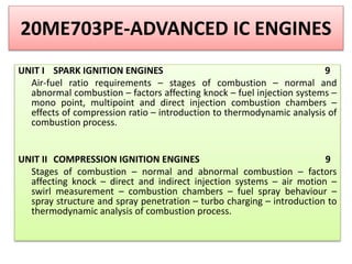
  • 1. 20ME703PE-ADVANCED IC ENGINES UNIT I SPARK IGNITION ENGINES 9 Air-fuel ratio requirements – stages of combustion – normal and abnormal combustion – factors affecting knock – fuel injection systems – mono point, multipoint and direct injection combustion chambers – effects of compression ratio – introduction to thermodynamic analysis of combustion process. UNIT II COMPRESSION IGNITION ENGINES 9 Stages of combustion – normal and abnormal combustion – factors affecting knock – direct and indirect injection systems – air motion – swirl measurement – combustion chambers – fuel spray behaviour – spray structure and spray penetration – turbo charging – introduction to thermodynamic analysis of combustion process.
  • 2. UNIT III EMISSION FORMATION AND CONTROL 9 Formation of NOX, HC/CO mechanism – smoke and particulate emissions – green house effect – methods of controlling emissions – three way catalytic converter – particulate trap – emission (HC, CO, NO and NOX) measuring equipment – smoke and particulate measurement – emission norms – national and international emission standards. UNIT IV ALTERNATE FUELS 9 Need for alternate fuels – alcohols, vegetable oils, bio-diesel, bio-gas, natural gas, liquefied petroleum gas and hydrogen – manufacturing, storage and safety properties – engine modifications and emissions – performance, combustion and emission characteristics of SI and CI engines. UNIT V RECENT TRENDS 9 Homogeneous charge compression ignition engine – lean burn engine – stratified charge engine – surface ignition engine – electronic engine management – common rail direct injection diesel engine – gasoline direct injection engine – hybrid electric vehicles – on board diagnostics – variable geometry turbochargers – NOx absorbers.
  • 4. TOPICS Air-fuel ratio requirements – stages of combustion – normal and abnormal combustion – factors affecting knock – fuel injection systems – mono point, multipoint and direct injection combustion chambers – effects of compression ratio – introduction to thermodynamic analysis of combustion process.
  • 5. AIR-FUEL MIXTURES An engine is generally operated at different loads and speeds. For this, proper air-fuel mixture should be supplied to the engine cylinder. Fuel and air are mixed to form three different types of mixtures. (1) Chemically Correct Mixture (2) Rich Mixture and (3) Lean Mixture
  • 6. β€’ Chemically correct or stoichiometric mixture is one in which there is just enough air for complete combustion of the fuel. For example, to burn one kg of octane (CsH18) completely 15.12 kg of air is required. β€’ Hence chemically correct A/F ratio for C8H18 is 15.12:1; usually approximated to 15:1. This chemically correct mixture will vary only slightly in numerical value between different hydrocarbon fuels. It is always computed from the chemical equation for complete combustion for a particular fuel.
  • 7. β€’ Complete combustion means all carbon in the fuel is converted to CO2 and all hydrogen to H2O. β€’ A mixture which contains less air than the stoichiometric requirement is called a rich mixture (example, A/F ratio of 12:1, 10:1 etc.). A mixture which contains more air than the stoichiometric requirement is called a lean mixture (example, A/F ratio of 17:1, 20:1 etc.).
  • 8. β€’ There is, however, a limited range of A/F ratios in a homogeneous mixture, only within which combustion in an SI engine will occur. Outside this range, the ratio is either too rich or too lean to sustain flame propagation. This range of useful A/F ratio runs from approximately 9:1 (rich) to 19:1 (lean) as indicated in Figure.
  • 9. . β€’ The A/F ratio will affect both the power output and the brake specific fuel consumption, as indicated by the typical curves shown in Figure. β€’ The mixture corresponding to the maximum output on the curve is called the best power mixture with an A/F ratio of approximately 12:1. β€’ The mixture corresponding to the minimum point on the bs fc curve is called the best economy mixture. The A/F ratio is approximately 16:1. β€’ It may be noted that the best power mixture is much richer than the chemically correct mixture and the best economy mixture is slightly leaner than the chemically correct.
  • 10. . β€’ Under normal conditions it is desirable to run the engine on the maximum economy mixture, viz., around 16:1 air-fuel ratio. For quick acceleration and for maximum power, rich mixture, viz., 12:1 air-fuel ratio is required.
  • 11. Automotive Engine Air-Fuel Mixture Requirements β€’ Actual air-fuel mixture requirements in an automotive engine vary considerably from the ideal conditions discussed in the previous section. For successful operation of the engine, the carburetor has to provide mixtures which follow the general shape of the curve ABCD (single cylinder) and A'B'C'D' (multicylinder) in Figure. β€’ which represents a typical automotive engine requirement. The carburetor must be suitably designed to meet the various engine requirements. (i) Idling (mixture must be enriched) (ii) Cruising (mixture must be leaned) (iii) High Power (mixture must be enriched)
  • 13. STAGES OF COMBUSTION IN SI ENGINES β€’ A typical theoretical pressure-crank angle diagram, during the process of compression (a-b), combustion (b-c) and expansion (c-d) in an ideal four-stroke spark ignition engine is shown in Figure. β€’ In an ideal engine, as can be seen from the diagram, the entire pressure rise during combustion takes place at constant volume i.e., at TDC. However, in an actual engine this does not happen. The detailed process of combustion in an actual SI engine is described below. Sir Ricardo, known as the father of engine research, describes the combustion process in a SI engine as consisting of three stages
  • 15. β€’ The first stage (A-B) is referred to as the ignition lag or preparation phase in which growth and development of a self propagating nucleus of flame takes place. This is a chemical process depending upon both temperature and pressure, the nature of the fuel and the proportion of the exhaust residual gas. Further, it also depends upon the relationship between the temperature and the rate of reaction. β€’ The second stage (B-C) is a physical one and it is concerned with the spread of the flame throughout the combustion chamber. The starting point of the second stage is where the first measurable rise of pressure is seen on the indicator diagram ie, the point where the line of combustion departs from the compression line (point B). This can be seen from the deviation from the motoring curve.
  • 16. β€’ During the second damage the flame propagates practically at a constant with Heat transfer to the cylinder wall is low, because only a small part of the burning mixture comes in contact with the cylinder wall during this period. β€’ The rate of heat release depends largely on the turbulence Intensity and also on the reaction rate which is dependent on the mixture composition. The rate of pressure rise is proportional to the rate of heat release because during this stage, the combustion chamber volume remains practically constant (since piston is near the top dead centre).
  • 17. β€’ The starting point of the third stage is usually taken as the instant at which the maximum pressure is reached on the indicator diagram (point C). The flame velocity decreases during this stage. The rate of combustion becomes low due to lower flame velocity and reduced flame front surface. Since the expansion stroke starts before this stage of combustion, with the piston moving away from the top dead centre, there can be no pressure rise during this stage.
  • 18. STAGES OF COMBUSTION IN SI ENGINE
  • 19. FACTORS INFLUENCING THE FLAME SPEED β€’ Turbulence β€’ Fuel-Air Ratio β€’ Temperature and Pressure β€’ Compression Ratio β€’ Engine Output β€’ Engine Size
  • 20. β€’ NORMAL COMBUSTION: In the normal combustion in S.I engine, the flame is started by the ignition of spark which travels across the combustion chamber gradually and runs the engine smoothly. β€’ ABNORMAL COMBUSTION: In normal combustion, the flame initiated by the spark travels across the combustion chamber in a fairly uniform manner. Under certain operating conditions the combustion deviates from its normal course leading to loss of performance and possible damage to the engine. This type of combustion may be termed as an abnormal combustion or knocking combustion. The consequences of this abnormal combustion process are the loss of power recurring pre-ignition and mechanical damage to the engine.
  • 21. KNOCK IN SI ENGINES β€’In a spark-ignition engine combustion which is initiated between the spark plug electrodes spreads across the combustible mixture. A definite flame front which separates the fresh mixture from the products of combustion travels from the spark plug to the other end of the combustion chamber. β€’Heat-release due to combustion increases the temperature and consequently the pressure, of the burned part of the mixture above those of the unburned mixture. In order to effect pressure equalization the burned part of the mixture will expand, and compress the unburned mixture adiabatically thereby increasing its pressure and temperature.
  • 22. β€’ This process continues as the flame front advances through the mixture and the temperature and pressure of the unburned mixture are increased further. β€’ If the temperature of the unburnt mixture exceeds the self- ignition temperature of the fuel and remains at or above this temperature during the period of preflame reactions (ignition lag), spontaneous ignition or auto ignition occurs at various pin-point locations. This phenomenon is called knocking. The process of auto ignition leads towards engine knock.
  • 23. Normal Vs Abnormal Combustion in SI Engine
  • 24. Knock Limited Parameters It should be the aim of the designer to reduce the tendency of knocking in the engine. In this connection, certain knock limited parameters are explained. β€’ Knock Limited Compression Ratio: The knock limited compression ratio is obtained by increasing the compression ratio on a variable compression ratio engine until incipient knocking is observed. Any change in operating conditions such as fuel-air ratio or in the engine design that increases the knock limited compression ratio is said to reduce the tendency towards knocking.
  • 25. β€’ Knock Limited Inlet Pressure: The inlet pressure can be increased by opening the throttle or increasing supercharger delivery pressure until incipient knock is observed. An increase in knock limited inlet pressure indicates a reduction in the knocking tendency. β€’ Knock Limited Indicated Mean Effective Pressure: The indicated mean effective pressure measured at incipient knock is usually abbreviated as Klimep. This parameter and the corresponding fuel consumption are obviously of great practical interest. An useful measure of knocking tendency called the performance number, has been developed from the concept of knock limited indicated mean effective pressure.
  • 26. EFFECT OF ENGINE VARIABLES ON KNOCK From the discussion on knock in the previous section, it may be seen that four major factors are involved in either producing or preventing knock. These are the temperature, pressure, density of the unburned charge and the time factors. Since, the effect of temperature, pressure and density are closely interrelated, these three are consolidated into one group and the time factors into another group
  • 27. Density Factors: Any factor in the design or operation of an engine which tends to reduce the temperature of the unburned charge should reduce the possibility of knocking by reducing the temperature of the end charge for auto ignition. Similarly, any factor which reduces the density of the charge tends to reduce knocking by providing lower energy release. Further, the effect of the following parameters which are directly or indirectly connected with temperature, pressure and density factors on the possibility of knocking is discussed below.
  • 28. Compression Ratio : Compression ratio of an engine is an important factor which determines both the pressure and temperature at the beginning of the combustion process. Increase in compression ratio increases the pressure and temperature of the gases at the end of the compression stroke This decreases the ignition lag of the end gas and thereby increasing the tendency for knocking. The overall increase in the density of the charge due to higher compression ratio increases the preflame reactions in the end charge thereby increasing the knocking tendency of the engine. The in- in the knocking tendency of the engine with increasing compression ratio is the main reason for limiting the compression ratio to a lower value.
  • 29. Mass of Inducted Charge: A reduction in the mass of the inducted large into the cylinder of an engine by throttling or by reducing the mount of supercharging reduces both temperature and density of the charge at the time of ignition. This decreases the tendency of knocking. Inlet Temperature of the Mixture: Increase in the inlet temperature of the mixture makes the compression temperature higher thereby, increasing the tendency of knocking. Further, volumetric efficiency will be lowered. Hence, a lower inlet temperature is always preferable to reduce knocking. It important that the temperature should not be so low as to cause starting and vaporization problems in the engine.
  • 30. Temperature of the Combustion Chamber Walls: Temperature of the combustion chamber walls play a predominant role in knocking. In order to prevent knocking the hot spots in the combustion chamber should be avoided. Since, the spark plug and exhaust valve are two hottest parts in the combustion chamber, the end gas shou should not be compressed against them Retarding the Spark Timing: By retarding the spark timing from the optimized timing, ie, having the spark closer to TDC. the peak pressures are reached farther down on the power stroke and are thus of lower magnitude. This might reduce the knocking. ld not be compressed against them.
  • 31. Power Output of the Engine: A decrease in the output of the engine decreases the temperature of the cylinder and the combustion chamber walls and also the pressure of the charge thereby lowering mixture and end gas temperatures. This reduces the tendency to knock. Time Factors: Increasing the flame speed or increasing the duration of the ignition lag or reducing the time of exposure of the unburned mixture to auto ignition condition will tend to reduce knocking. The following factors, in most cases reduce the possibility of knocking.
  • 32. Turbulence: Turbulence depends on the design of the combustion chamber and on engine speed. Increasing turbulence increases the flame speed and reduces the time available for the end charge to attain autoignition conditions thereby decreasing the tendency to knock. Engine Speed: An increase in engine speed increases the turbulence o the mixture considerably resulting in increased flame speed, and reduces the time available for preflame reactions. Hence knocking tendency is reduce at higher speeds.
  • 33. Flame Travel Distance: The knocking tendency is reduced by shortening the time required for the flame front to traverse the combustion chamber. Engine size and spark plug position are the three important factors governing the fame travel distance. Engine Size: The flame requires a longer time to travel across the combustion chamber of a larger engine. Therefore, a larger engine has a greater tendency knocking than a mater engine since there is more time for the end gas to autoignite. Hence, and SI engine is generally limited to size of about 150 mm bore.
  • 34. Typical Combustion Chamber The design of the combustion chamber for an SI engine has an important influence on the engine performance and its knocking tendencies. The design involves the shape of the combustion chamber, the location of spark plug and the location of inlet and exhaust valves. Because of this importance, the combustion chamber design has been a subject of considerable amount of research and development in the last fifty years. It has resulted in the raising of the compression ratio of the engine from 4 before the first world
  • 35. war period to 11 in the present times with special combustion chamber designs and suitable antiknock fuels. The important requirements of an SI engine combustion chamber are to provide high power output with minimum octane requirement, high thermal efficiency and smooth engine operation. Combustion chambers must be designed carefully, keeping in mind the following general objectives. β€’ Smooth Engine Operation β€’ Moderate Rate of Pressure Rise β€’ Reducing the Possibility of Knocking β€’ High Power Output and Thermal Efficiency
  • 36.
  • 37. TYPES OF INJECTION SYSTEMS IN SI ENGINE INDIRECT FUEL INJECTION SYSTEM (manifold injection system) GASOLINE DIRECT FUEL INJECTION SYSTEM Single Point Fuel Injection System Multi Point Fuel Injection System 2. Port Injection 1. Throttle body injection 1. Throttle body injection 2. Port Injection
  • 38. CONTINUOUS INJECTION SYSTEMS This system usually has a rotary pump. The pump maintains a fuel line gauge pressure of about 0.75 to 1.5 bar. The system injects the fuel through a nozzle located in the manifold immediately downstream of the throttle plate. In a supercharged engine, fuel is injected at the entrance of the supercharger. The timing and duration of the fuel injection is determined by Electronic Control Unit (ECU) depending upon the load and speed.
  • 39. TIMED FUEL INJECTION SYSTEM This system has a fuel supply pump which sends fuel at a low pressure of about 2 bar when the engine is running at maximum speed. A fuel metering or injection pump and a nozzle are the other parts of the system. The nozzle injects the fuel in the manifold or the cylinder head port at about 6.5 bar or into the combustion chamber at pressures that range from 16 to 35 bar. Timed injection system injects fuel usually during the early part of the suction stroke. During maximum power operation injection begins after the closure of the exhaust valve and ends usually after BDC. Direct in-cylinder injection is superior and always desirable and better compared to manifold
  • 40. GASOLINE INJECTION IN FOUR STROKE ENGINES Different methods of injection
  • 42. Fuel injection is a system for mixing fuel with air in an internal combustion engine. The functional objectives for fuel injection systems vary but all of them share the central task of supplying fuel to the combustion process. MONOPOINT INJECTION
  • 43. In the Multipoint Injection System, we have one injector per cylinder, the injector injects the fuel into the admission valve which admits the fuel and air into the cylinder. This gives an individual control on this cylinder, improving the fuel consumption in relation of the Single point injection. MULTIPOINT INJECTION
  • 44.
  • 45. THERMODYNAMIC ANALYSIS OF COMBUSTION PROCESS The main drawback of the Carnot cycle is its impracticability due to high pressure and high volume ratios employed with comparatively low mean effective pressure. Nicolaus Otto (1876), proposed a constant-volume heat addition cycle which forms the basis for the working of today's spark-ignition engines. The cycle is shown on p-V and T-S diagrams in Fig.
  • 46. When the engine is working on full throttle, the processes 0-1 and 1-0 on the P-V diagram represents suction and exhaust processes and their effect is nullified. The process 1-2 represents isentropic compression of the air when the piston moves from bottom dead centre to top dead centre. During the process 2-3 heat is supplied reversibly at constant volume. This process corresponds to spark-ignition and combustion in the actual engine. The processes 3-4 and 4-1 represent isentropic expansion and constant volume heat rejection respectively
  • 47. OTTO CYCLE (P-V and T-S diagram)