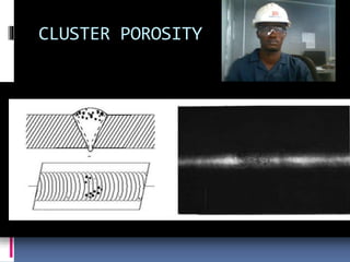
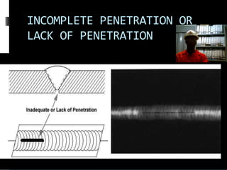
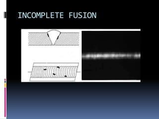
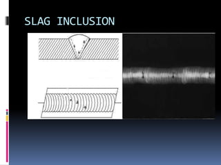
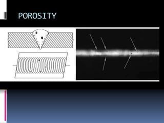
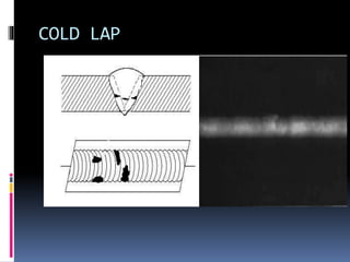
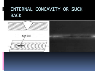
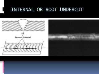
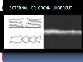
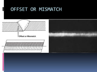
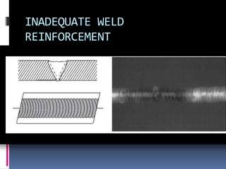
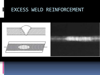
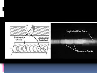
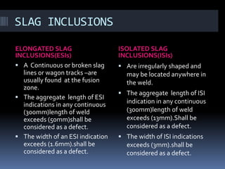
CLUSTER POROSITY
INCOMPLETE PENETRATION OR
LACK OF PENETRATION
INCOMPLETE FUSION
SLAG INCLUSION
POROSITY
COLD LAP
INTERNAL CONCAVITY OR SUCK
BACK
INTERNAL OR ROOT UNDERCUT
EXTERNAL OR CROWN UNDERCUT
OFFSET OR MISMATCH
INADEQUATE WELD
REINFORCEMENT
EXCESS WELD REINFORCEMENT
CRACK
TUNGSTEN INCLUSIONS
OXIDE INCLUSIONS
BURN-THROUGH
ASMEC V
ASMEC SECTIONV
ď‚§ ASME SectionV states that
the radiation energy
ď‚§ used shall achieve the
density and IQI image
ď‚§ requirements given in ASME
SectionV Article 2
SLAG INCLUSIONS
ELONGATED SLAG
INCLUSIONS(ESIs)
ISOLATED SLAG
INCLUSIONS(ISIs)
ď‚§ A Continuous or broken slag
lines or wagon tracks –are
usually found at the fusion
zone.
ď‚§ The aggregate length of ESI
indications in any continuous
(300mm)length of weld
exceeds (50mm)shall be
considered as a defect.
ď‚§ The width of an ESI indication
exceeds (1.6mm).shall be
considered as a defect.
ď‚§ Are irregularly shaped and
may be located anywhere in
the weld.
ď‚§ The aggregate length of ISI
indication in any continuous
(300mm)length of weld
exceeds (13mm).Shall be
considered as a defect.
ď‚§ The width of ISI indications
exceeds (3mm).shall be
considered as a defect.
CLUSTER POROSITY
CLUSTER POROSITY

CLUSTER POROSITY

Editor's Notes

  • #2 Cluster porosity is caused when flux coated electrodes are contaminated with moisture. The moisture turns into a gas when heated and becomes trapped in the weld during the welding process. Cluster porosity appear just like regular porosity in the radiograph but the indications will be grouped close together.
  • #3 Incomplete penetration (IP) or lack of penetration (LOP) occurs when the weld metal fails to penetrate the joint. It is one of the most objectionable weld discontinuities. Lack of penetration allows a natural stress riser from which a crack may propagate. The appearance on a radiograph is a dark area with well-defined, straight edges that follows the land or root face down the center of the weldmentDefinition A situation where the weld metal does not penetrate as deeply as required. Preventive Action 1. Increase the bevel angle and/or root opening of the fit-up. Do not exceed the requirements of the joint design. 2. Ensure bevel edges of both members are lined up properly. 3. Increase amps/volts. 4. Decrease travel speed. 5. Maintain appropriate arc length/wire stickout. 6. Adjust torch/rod angle. Corrective Action 1. Grind or carbon arc the weld to sound metal. Note: Backgouge 2nd side to full penetration (remove fusion lines). Often, more than one fusion line will be present during back gouging. 2. Weld repair the affected area
  • #4 Incomplete fusion is a condition where the weld filler metal does not properly fuse with the base metal. Appearance on radiograph: usually appears as a dark line or lines oriented in the direction of the weld seam along the weld preparation or joining area. A situation where the weld metal does not fuse or completely bond with the base metal or previously. deposited weld metal. Preventive Action 1. Increase amps/volts. 2. Decrease travel speed. 3. Maintain appropriate arc length/wire stickout. 4. Adjust torch/rod angle. 5. Ensure previous beads are free of overlap (bead roll-over) and slag prior to welding additional passes. Corrective Action 1. Grind or carbon arc the weld to sound metal. 2. Weld repair the affected area
  • #5 Slag inclusions are nonmetallic solid material entrapped in weld metal or between weld and base metal. In a radiograph, dark, jagged asymmetrical shapes within the weld or along the weld joint areas are indicative of slag inclusions. Preventive Action Note: Slag is a byproduct of the welding process that cannot be prevented. Below are some actions that make slag removal easier. 1. Adjust amps/volts. 2. Maintain a consistent travel speed. 3. Maintain an appropriate arc length/wire stickout. 4. Adjust torch/rod angle. 5. Sequence weld passes so that the toes of the beads sufficiently overlap one another, minimizing valleys. Corrective Action 1. Completely remove slag from all intermediate weld areas. 2. Remove all loose slag with a needle gun. 3. Grind all tightly adhering, unacceptable slag from the surface of the base material or weld.
  • #19 Porosity is the result of gas entrapment in the solidifying metal. Porosity can take many shapes on a radiograph but often appears as dark round or irregular spots or specks appearing singularly, in clusters, or in rows. Sometimes, porosity is elongated and may appear to have a tail. This is the result of gas attempting to escape while the metal is still in a liquid state and is called wormhole porosity. All porosity is a void in the material and it will have a higher radiographic density than the surrounding area. . Porosity is the result of gas entrapment in the solidifying metal. Porosity can take many shapes on a radiograph but often appears as dark round or irregular spots or specks appearing singularly, in clusters, or in rows. Sometimes, porosity is elongated and may appear to have a tail. This is the result of gas attempting to escape while the metal is still in a liquid state and is called wormhole porosity. All porosity is a void in the material and it will have a higher radiographic density than the surrounding area. Preventive Action 1. Remove contaminants from the joint (rust, grease, moisture, etc.) prior to welding. 2. Maintain filler metal control requirements. 3. Maintain appropriate arc length/wire stickout. 4. Adjust torch/rod angle. 5. Use the largest size gas cup possible and keep it free of spatter. 6. Position wind screens between the welding operation and any heavy flow of air. Corrective Action 1. Completely remove porosity from all intermediate weld areas. 2. Grind or carbon arc the affected area until the unacceptable porosity is removed from the weld. 3. Weld repair the affected area, if needed
  • #20 Cold lap is a condition where the weld filler metal does not properly fuse with the base metal or the previous weld pass material (interpass cold lap). The arc does not melt the base metal sufficiently and causes the slightly molten puddle to flow into the base material without bonding.
  • #21 Internal concavity or suck back is a condition where the weld metal has contracted as it cools and has been drawn up into the root of the weld. On a radiograph it looks similar to a lack of penetration but the line has irregular edges and it is often quite wide in the center of the weld image
  • #22 Internal or root undercut is an erosion of the base metal next to the root of the weld. In the radiographic image it appears as a dark irregular line offset from the centerline of the weldment. Undercutting is not as straight edged as LOP because it does not follow a ground edge. A groove melted into the base metal and left unfilled by weld metal. Preventive Action 1. Decrease amps/volts. 2. Decrease travel speed. 3. Maintain appropriate arc length/wire stickout. 4. Adjust torch/rod angle. 5. Feed more wire into the puddle when manual TIG welding. 6. Increase stop time (dwell time) on weaved beads. 7. Use undercut gauge to verify acceptability. Corrective Action 1. Grind the toe of the weld until the unacceptable undercut blends smoothly into the base material. 2. Weld repair the affected area, if needed
  • #23 External or crown undercut is an erosion of the base metal next to the crown of the weld. In the radiograph, it appears as a dark irregular line along the outside edge of the weld area.
  • #24 Offset or mismatch are terms associated with a condition where two pieces being welded together are not properly aligned. The radiographic image shows a noticeable difference in density between the two pieces. The difference in density is caused by the difference in material thickness. The dark, straight line is caused by the failure of the weld metal to fuse with the land areaNOTE: Offset is one of the major causes of inservice failures! Preventive Action 1. Ensure installing trade provides proper fit-up prior to welding. 2. Use approved temporary attachments (strongbacks, flatbar, etc.), as needed to reduce distortion. 3. Gauge for offset acceptability prior to tack welding with bridgecam or finger gauges. 4. Apply sufficient block tacks prior to welding. Note: Stop welding and immediately notify your foreman anytime unacceptable offset occurs. Corrective Action 1. Installing trade may have to cut apart and re-fit the joint within tolerance. 2. Offset may be repaired by applying weld buildup to the appropriate taper.
  • #25 Inadequate weld reinforcement is an area of a weld where the thickness of weld metal deposited is less than the thickness of the base material. It is very easy to determine by radiograph if the weld has inadequate reinforcement, because the image density in the area of suspected inadequacy will be higher (darker) than the image density of the surrounding base material. Preventive Action 1. During welding of the reinforcement, gauge bead heights in any location that appears to be lower than the rest of the bead. 2. Adjust amps/volts. 3. Slow travel speed to allow increased weld puddle volume. 4. Sequence weld passes so that the toes of the beads sufficiently cover one another, minimizing valleys. Corrective Action Apply additional weld beads until the joint is adequatly filled. (flush or above)
  • #26 Excess weld reinforcement is an area of a weld that has weld metal added in excess of that specified by engineering drawings and codes. The appearance on a radiograph is a localized, lighter area in the weld. A visual inspection will easily determine if the weld reinforcement is in excess of that specified by the engineering requirements. Preventive Action 1. Adjust amps/volts. 2. Increase travel speed. 3. Maintain appropriate wire stickout. 4. Adjust torch/rod angle. 5. Sequence beads so that the toes do not excessively overlap one another, creating high spots in the reinforcement. Corrective Action Grind or carbon arc areas of weld reinforcement that exceed the maximum allowable height (if applicable
  • #27 Cracks can be detected in a radiograph only when they are propagating in a direction that produces a change in thickness that is parallel to the x-ray beam. Cracks will appear as jagged and often very faint irregular lines. Cracks can sometimes appear as "tails" on inclusions or porosity. NOTE: Cracks are the most serious defect! Preventive Action 1. Remove contaminants from the joint (rust, grease, moisture, etc.) prior to welding. 2. Apply and maintain required preheat. 3. Do not allow the base material to cool too quickly. 4. Maintain filler metal control requirements. 5. Use correct filler metal type for the joint. 6. Apply proper bead size and sequencing to eliminate excessive distortion and/or stress in the base material. Corrective Action Repair in accordance with local procedures
  • #28 Tungsten inclusions. Tungsten is a brittle and inherently dense material used in the electrode in tungsten inert gas welding. If improper welding procedures are used, tungsten may be entrapped in the weld. Radiographically, tungsten is more dense than aluminum or steel, therefore it shows up as a lighter area with a distinct outline on the radiograph
  • #29 Oxide inclusions are usually visible on the surface of material being welded (especially aluminum). Oxide inclusions are less dense than the surrounding material and, therefore, appear as dark irregularly shaped discontinuities in the radiograph.
  • #30 Burn-Through results when too much heat causes excessive weld metal to penetrate the weld zone. Often lumps of metal sag through the weld, creating a thick globular condition on the back of the weld. These globs of metal are referred to as icicles. On a radiograph, burn-through appears as dark spots, which are often surrounded by light globular areas (icicles). Preventive Action 1. Reduce amps/volts. 2. Increase travel speed. 3. Maintain appropriate arc length/wire stickout. 4. Use ceramic tape or approved metal backing strap on areas with root gap. Corrective Action 1. Place ceramic tape or approved metal backing strap on the bottom side of the hole. 2. Weld repair the first side of the hole from the easiest side to weld. 3. Once sufficient weld metal has been deposited on the easiest top side, grind or carbon arc the other side of the hole to sound metal. 4. Weld the other side of the hole to the appropriate size or height