Download to read offline

![5
The Elmo Solution
How the commutation works
Movements Description
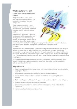
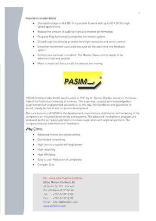
At start-up, the location and orientation of the planar
motor is unknown. The planar motor can only acquire
force if it is positioned correctly.
All feedbacks must be inactive and all the Y-axis SimplIQ-
Whistle drives must move with the same speed relative to
the frame,
The planar motor moves to the outer frame in the
“Stepper” mode (not using the feedback), to arrive at the
correct starting position.
The twist is corrected and the SimplIQ-Whistle drives on
the Y-axis are commutated.
The planar motor must move to a corner to define its
second position. While moving, the motor must
continually verify that it is always correctly positioned with
respect to the frame.
From the corner, the motor can commutate the X-axis.
With all the axes commutating, the planar motor is able to
move in position mode and the Master-Slave protection is
activated.
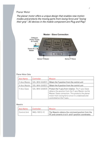
How does the anti-angle work?
Because the communication is not sufficiently fast to handle the synchronization, Elmo
Motion Control recommends that both devices be set up in a Position-Follower
configuration. The YA[N]command for the SimplIQ-Whistle defines the behavior and
direction of the auxiliary position sensor signals. YA[4] is used to specify that the auxiliary
encoder pins shall be outputs, and shall repeat the pulses of the main position
incremental or analog sensors. This mode is used to enable other drives to follow,
without electrically overloading the main position sensor.
The main position incremental encoder is direct on
every controller. The Master is controlled in position or
velocity mode and sends its position over the auxiliary
encoder. YA[4] = 4 specifies that there are no auxiliary
encoder inputs and that the auxiliary encoder pin output
repeats the main encoder input (or produces an
emulated encoder signal for drives with analog encoder
or resolver feedback options).
The situation is similar for the Slave. YA[4] = 2 sets up an auxiliary encoder entry that is
used as input for external quadrate incremental encoder signals.
Master Slave
Main Feedback](https://image.slidesharecdn.com/closed-loop-planar-servo-motor-141221061153-conversion-gate01/85/Closed-loop-planar-servo-motor-5-320.jpg)
![6
Program example:
#@AUTOEXEC
YA[4]=2 // Set AUX feedback as quadrate incremental encoder command input.
FR[3]=1 // Set follower ratio to 100%
AG[2]=0 // Disable influence of analog input
RM=1 // Enable reference mode
UM=5 // Set position mode
MO=1 // Motor on
BG // Begin motion
Advantages of using the Maestro as a control unit
Movement Description
The Maestro controls only the Master Axis for the planar
motor.
Setting up the movement parameters. Both axes are
controlled as vectors. At the beginning, after each
movement, we want the motor to wait for new
commands:
v1.attach()
v1.vsp=70000 // max velocity
v1.vse=0 //* end velocity*/
Achieving point-to-point movement. Initially, we want
the motor to start at 0 and move to a position in the field.
v1.line(70000, 100000) //go to position (7000,10000)
v1.bg //action!
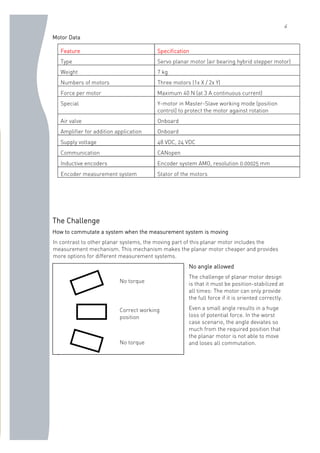
Achieving more interesting motion. It is more useful to
work as a vector from this location.
What we want:
Radius 50000,
Start angle 180°
3/4 turn=270°
v1.circle(50000, 180, 270) // create circle
v1.bg // start motion
Radius 50000
start angle 180°
(70000,10000)](https://image.slidesharecdn.com/closed-loop-planar-servo-motor-141221061153-conversion-gate01/85/Closed-loop-planar-servo-motor-6-320.jpg)

The document describes a planar servo motor system consisting of three motors (1 x-axis, 2 y-axis) that move on an air bearing. A master-slave configuration is used where the y-axis motors are controlled by a master controller to prevent rotation and loss of force. The measurement system is on the moving part, presenting a challenge for commutation. This is solved by using position follower mode where the master sends its position to slaves without overloading the sensor. The Maestro controller handles motion profiles like point-to-point and circular interpolation moves.


