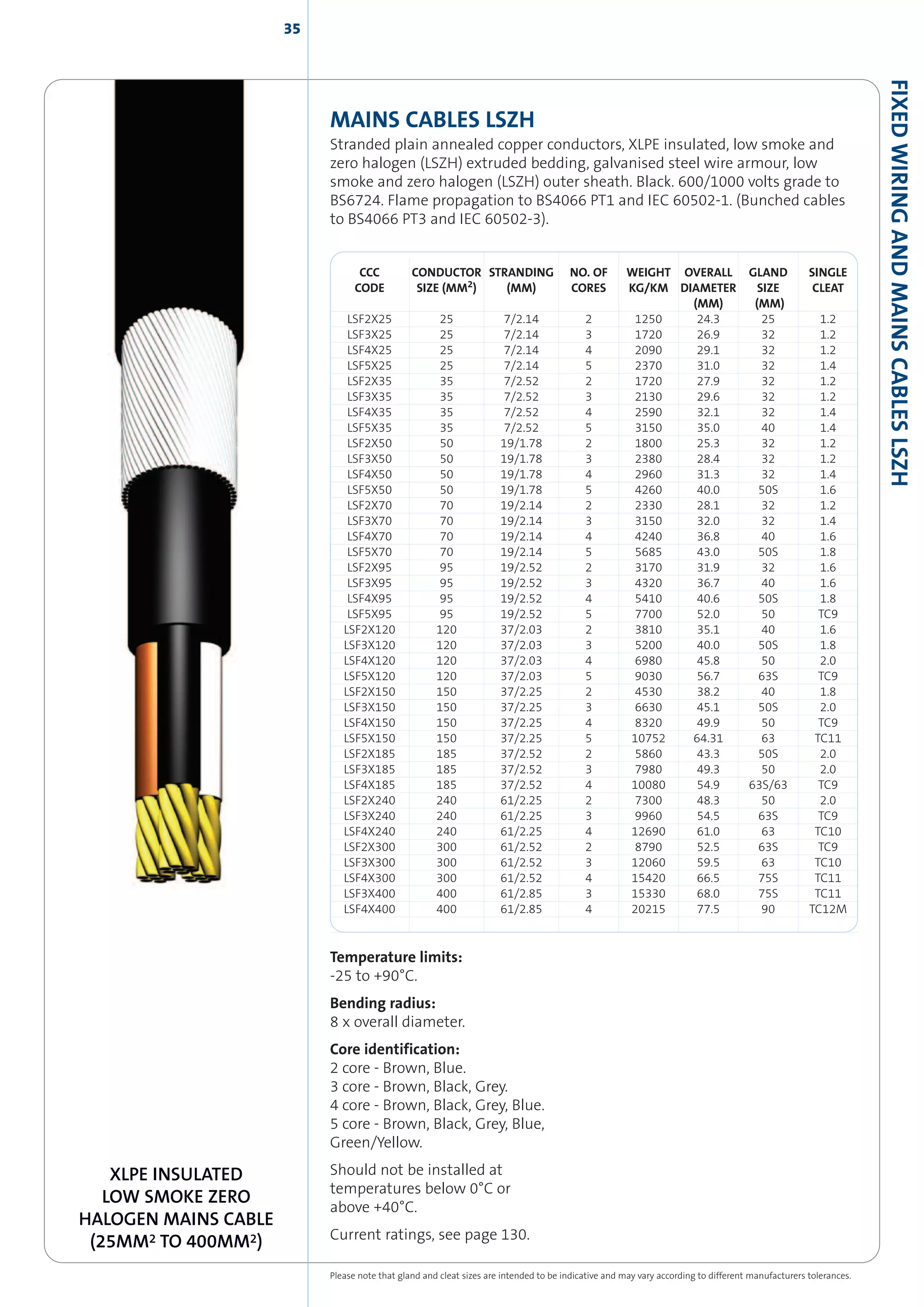
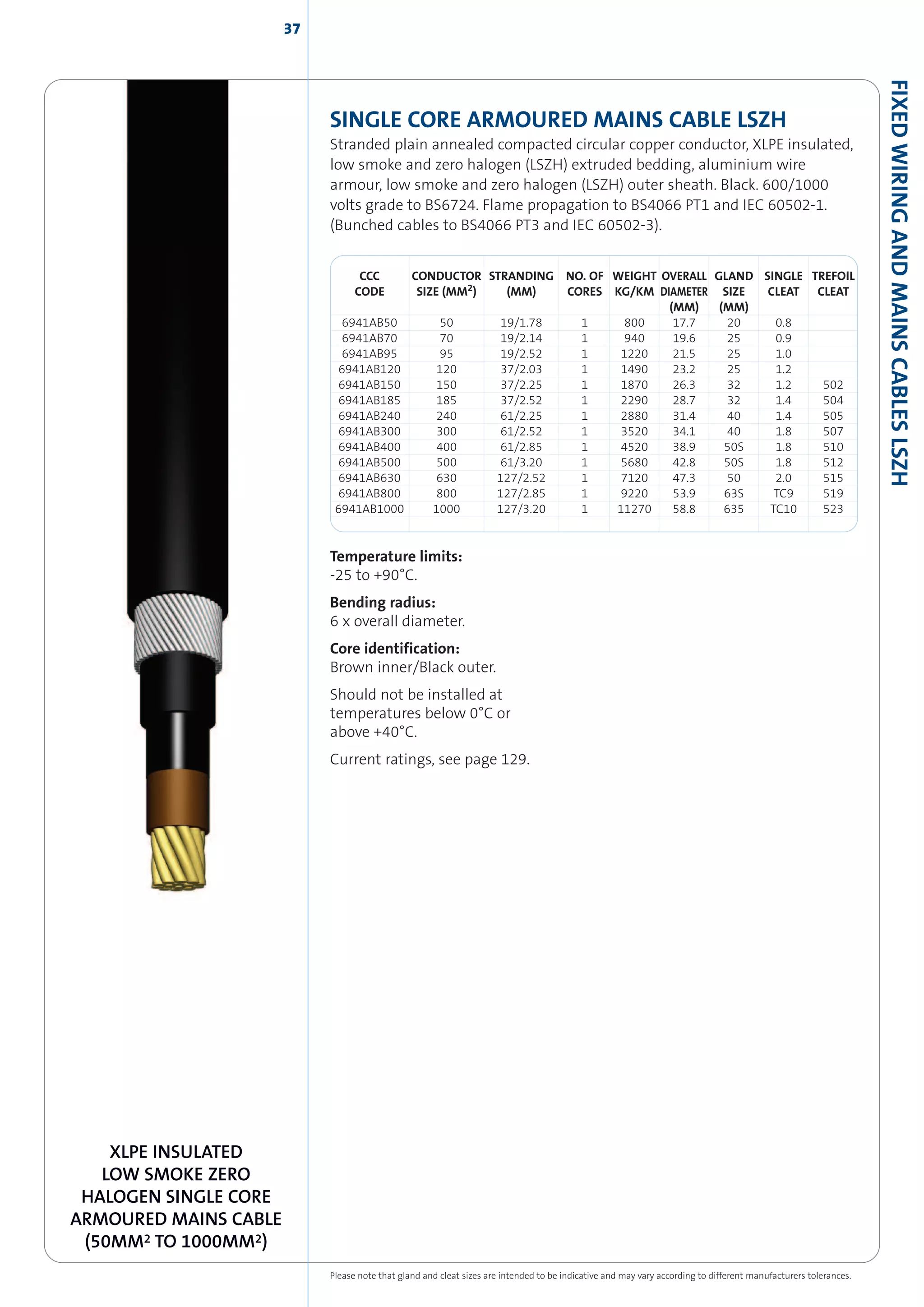
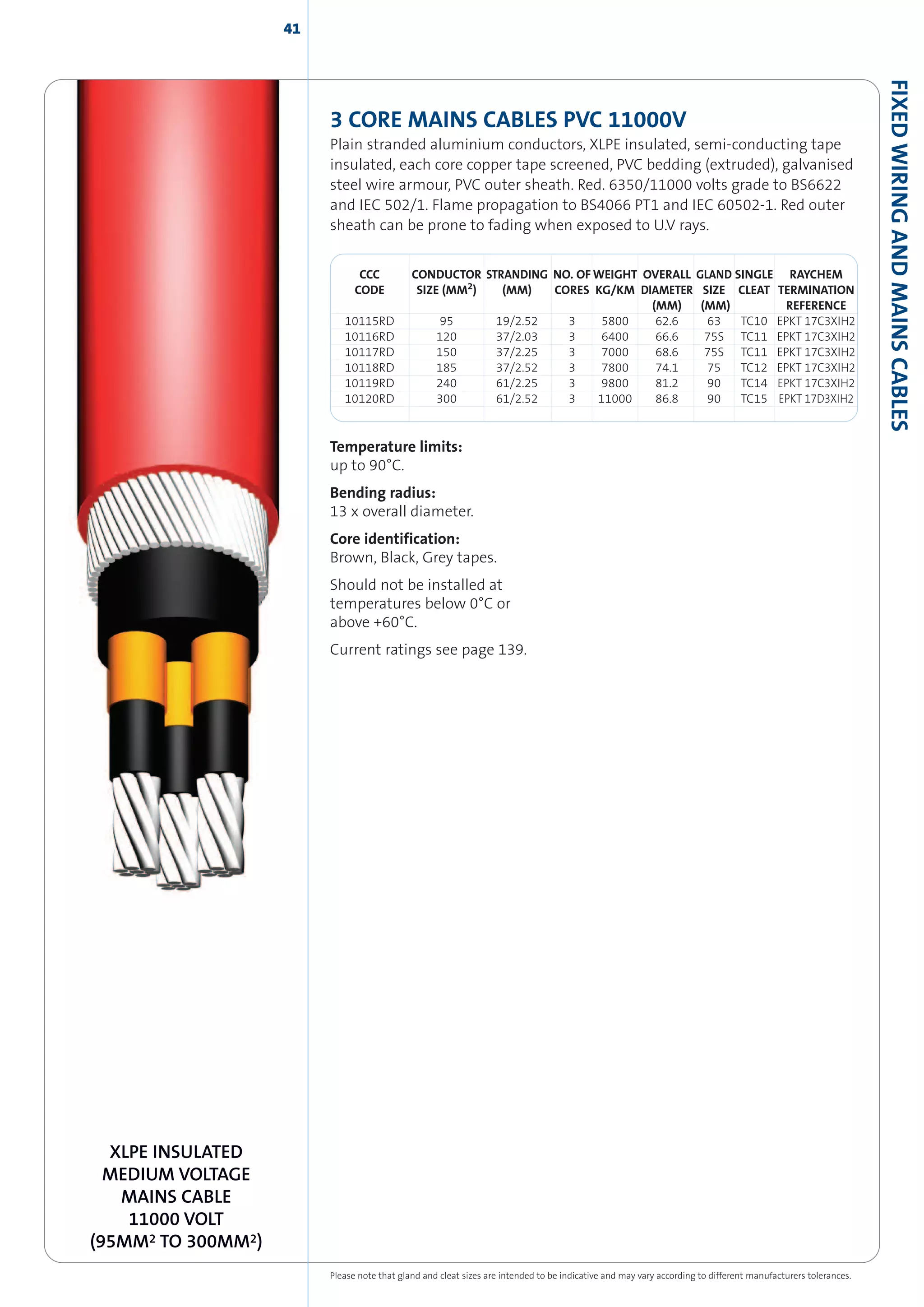
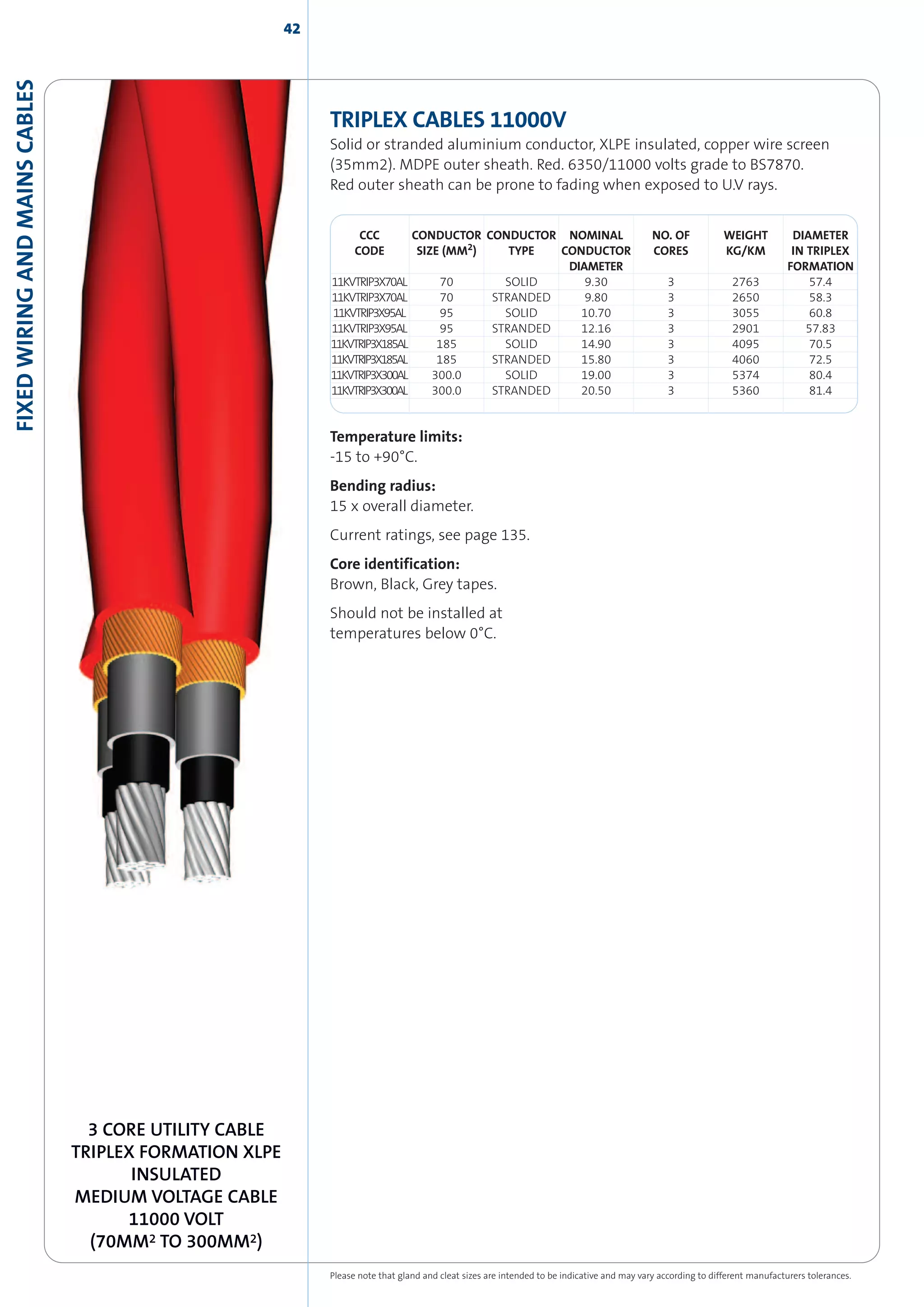
T H E
C A B L E
A N D
A C C E S S O R Y
C A T A L O G U E
A W O R L D P O W E R I N C A B L E S U P P L Y
CLEVELANDCABLELOCATIONS 2
CLEVELAND CABLE LOCATIONS
3
CLEVELANDCABLECOMPANY
As is illustrated within our catalogue, we stock a
comprehensive range of cables for every
conceivable application. All types shown are
considered as standard items to our range and are
always available for immediate delivery. Our stocks
are extremely large and unrivalled in the industry.
We are fortunate to have a very
experienced and dedicated team of
people who are able to assist and
advise. Additionally our policy of
continuing investment in the best
available technology, warehousing,
handling and measuring equipment
and delivery vehicles enables us to
guarantee all our customers an
extremely high quality service.
Enquiries are welcome from customers worldwide. Our export service is efficient
and reliable with the ability to ship by air or sea freight to any destination.
Please feel free to contact the depot of your
choice for an immediate, professional and
trouble free service.
Middlesbrough 01642 241133
Bristol 01179 382222
Glasgow 0141 6465000
Milton Keynes 01908 221414
London 0208 3114141
Newcastle 0191 2633363
Warrington 01925 655383
4CLEVELANDCABLECOMPANY
CLEVELAND CABLE COMPANY
Cleveland Cable Company, established in 1978, is
undoubtedly the foremost distributor of electrical
cables in Great Britain and possibly Europe.
The Head Office and principal stocking location is located at Middlesbrough in the
North East of England. This site covers an area of twelve acres and includes over
160,000 square feet of warehousing. Additionally there are regional depots at
Bristol, Glasgow, London, Milton Keynes, Newcastle and Warrington. Each location
holds comprehensive stocks and is equipped with the most modern handling and
measuring equipment. Deliveries are made by our own fleet of purpose-designed
vehicles, all of which are fitted with hydraulic lifting equipment for safe offloading
onsite and also efficient collection of empty drums.
6
GLAND SELECTION GUIDELINES
There are many factors to considered when selecting
cable glands for industrial installations. Neglecting to
give due attention to these factors could cause
unnecessary difficulties at a crucial point in time where
most inconvenience and expense can result. It is most
desirable to avoid discovering that, once all other
equipment is on site or installed, the glands have not
been ordered or are the wrong size or type.
Good practise would be to allocate some planning and
preparation time to cable gland selection. This will help
avoid the possible disruption which could result at a
critical point of the installation process. In the event of a
project schedule of cables being available Cleveland
Cable Company are happy to offer a gland selection and
sizing service. Please contact any of our depots for
further information or assistance.
Here is a summary of some aspects to carefully consider
when selecting cable glands.
• Identify the type of cable to be used.
• Check the construction, size and material properties
of the cable.
• Check the type and material of the cable armour(*)
• Check the short circuit fault current rating of the
cable armour(**)
• Check the actual diameter of the inner bedding
(where present) against this catalogue.
• Check the actual diameter of the lead covering (where
present) against this catalogue.
• Check the actual size of the overall cable diameter
against this catalogue.
• Check the size and type or armour or braid (where
present) against this catalogue.
• Check any special environmental requirements in
relation to corrosion protection
• Check the material of the mating electrical enclosures
to eliminate dis-similar metals.
• Consider whether any protective plating is required to
be applied to the cable gland.
• Check the type and size of the cable entry hole in the
mating electrical equipment.
• Check the ingress protection rating of the electrical
equipment or site standard.
• Check whether a single or double seal cable gland is
required.
• Check whether an entry thread seal is required for
IP66 (or IP67/IP68) conditions.
• Check whether fixing accessories such as locknuts
and serrated washers are required.
• Check whether earth tags are required. (**)
• Check whether shrouds are required.
• Select a corresponding cable gland type from this
catalogue.
• For installations in Hazardous Areas, special
considerations should be taken into account to ensure
compliance with national or international codes of
practice.
• Check whether a thread conversation adaptor or
reducer is required to make the installation.
• Select corresponding adaptors or reducers from this
catalogue.
• Check whether any stopper plugs are required to close
unused cable entries.
• Select corresponding stopper plugs from this
catalogue.
Note (*): If the cable armour is of a non standard
material, i.e. Aluminium Wire Armour, it may be
necessary to consider an alternative cable gland material,
e.g. Aluminium.
Note (**): For certain medium voltage and high voltage
cables where the fault current carrying capacity of the
cable armour is greater that that of the standard earth
tag it may be necessary to consider a cable gland utilising
the a heavy Cast Integral Earth Lug (CIEL) option which
can be identified in the body of this catalogue.
7
CONTENTS
SECTION 1 Low Voltage PVC Fixed Wiring & Mains Cables
6491X (HO7V-R) PVC insulated wiring, 1.5mm2
– 630mm2
........................................................................................................................12
Bare copper strand, soft drawn to BS6360/81, 6mm2 - 400mm2............................................................................................................12
6181Y PVC insulated, PVC sheathed surface wiring, 1.5mm2
– 120mm2
..............................................................................................13
624*Y PVC insulated, PVC sheathed surface wiring, 1mm2
– 16mm2
....................................................................................................13
BS5467 Mains & control, XLPE, PVC SWA, PVC, 1.5mm2
– 16mm2
including multicores................................................................14
BS5467 Mains, XLPE, PVC, SWA, PVC, copper conductors, 25mm2
– 400mm2
....................................................................................15
BS5467 Mains, XLPE, PVC, SWA, PVC, aluminium conductors, 25mm2
– 300mm2
............................................................................16
BS7889 Mains, single core, XLPE, PVC, non-armoured, 6mm2
– 1000mm2
..........................................................................................17
BS5467 Mains, single core, XLPE, PVC, aluminium wire armoured, PVC, 50mm2
–1000mm2
......................................................18
Mines & Quarries Mains, XLPE, PVC, SWA, PVC, with 60% Conductivity in armour, 10mm2
– 300mm2
................................19
EEMUA 133 Multicore, XLPE, lead sheathed, PVC, SWA, PVC, Control cable for petro-chemical industries, 1.5mm2
– 4mm2
......20
EEMUA 133 Mains, XLPE, lead sheathed, PVC,SWA, PVC, for petro-chemical industries, 1.5mm2
– 16mm2
..........................21
EEMUA 133 Mains, XLPE, lead sheathed, PVC, SWA, PVC, for petro-chemical industries, 25mm2
– 300mm2
......................22
Cathodic Protection Cables. XLPE, PVC, and XLPE, PVC, SWA, PVC, 6mm2
– 185mm2
......................................................................23
Concentric, split & straight, single phase service cable, 4mm2
– 35mm2
............................................................................................24
SECTION 2 3300V Mains Cable
BS5467 Mains, single core XLPE, PVC, aluminium wire armoured, PVC, 3300V, 120mm2
– 630mm2
......................................26
BS5467 Mains three core, XLPE, PVC, SWA, PVC, 3300V, 16mm2
– 300mm2
........................................................................................27
Mines & Quarries Mains, XLPE, PVC, SWA, PVC, with 60% conductivity in armour, 3300V, 16mm2
– 300mm2
..................28
EEMUA 133 Mains, XLPE, Lead sheathed, PVC, SWA, PVC, for petro-chemical industries, 3300V, 25mm2
– 300mm2
......29
SECTION 3 LSZH Fixed Wiring & Mains Cables
6491B (H07Z-R) LSZH insulated wiring, 1.5mm2
– 630mm2
......................................................................................................................32
6181B XLPE insulated, LSZH sheathed, surface wiring, 1.5mm2
– 120mm2
........................................................................................33
624*B LSZH insulated, LSZH sheathed surface wiring 1.5mm2
– 16mm2
..............................................................................................33
BS6724 Mains & control, XLPE, LSZH, SWA, LSZH, 1.5mm2
– 16mm2
including multicores..........................................................34
BS6724 Mains, XLPE, LSZH, SWA, LSZH, 25mm2
– 400mm2
........................................................................................................................35
BS6724 Mains, single core, XLPE, LSZH, 50mm2
– 1000mm2
......................................................................................................................36
BS6724 Mains, single core, XLPE, LSZH, aluminium wire armoured, LSZH, 50mm2
– 1000mm2
................................................37
BS8436 Protected fixed wiring cable, 1mm2
– 6mm2
....................................................................................................................................38
8
SECTION 4 Medium Voltage 11000V & above
BS6622 Mains, single core, XLPE, CTS, PVC, aluminium wire armoured, PVC, 11000V, 50mm2
– 630mm2
............................40
BS6622 Mains, three core, XLPE, CTS, PVC, SWA, PVC, 11000V, 25mm2
– 400mm2
..........................................................................40
BS6622 Mains, three core, aluminium conductor, XLPE, CTS, PVC, SWA, PVC, 11000V, 95mm2
– 300mm2
............................41
Triplex, BS7870, aluminium conductor XLPE, CTS, MDPE, 11000V, utility cable, 70mm2
– 300mm2
........................................42
Paper insulated, BS6480 Mains, three core, SWA, PVC, 11000V, 25mm2
– 400mm2
........................................................................43
BS7835 Mains, single core, XLPE, CTS, LSZH, aluminium wire armoured, LSZH, 11000V, 50mm2
– 630mm2
........................44
BS7835 Mains, three core, XLPE, CTS, LSZH, SWA, LSZH, 11000V, 35mm2
– 400mm2
......................................................................44
SECTION 5 Fire Protection, Alarm & Security Cables
Mineral Insulated............................................................................................................................................................................................................46
BS5839/BS7629 Fire performance alarm and security cable, 1mm2
– 4mm2
....................................................................................47
BS6387/BS7846Mainsandcontrol,micatape,XLPE,LSZH,SWA,LSZH,fireresistant,1.5mm2
–16mm2
,includingmulticores................48
BS6387/BS7846 Mains, mica tape, XLPE, LSZH, SWA, LSZH, fire resistant, 25mm2
– 400mm2
....................................................49
SECTION 6 Flexible Cables, PVC
218*Y ( H03VV-F) PVC, PVC, 0.5mm2
– 0.75mm2
..............................................................................................................................................52
318*Y (H05VV-F) PVC, PVC, 0.5mm2
– 2.5mm2
................................................................................................................................................52
309*Y Heat resisting PVC, PVC, 0.5mm2
– 2.5mm2
........................................................................................................................................53
Artic grade low temperature flex, 1.5mm2
– 4mm2
........................................................................................................................................53
318*B (H05ZIZI-F) LSZH, LSZH, 0.75mm2
– 2.5mm2
........................................................................................................................................54
YY Control cable, 0.75mm2
– 1.5mm2
....................................................................................................................................................................55
YY Control cable, 2.5mm2
– 50mm2
........................................................................................................................................................................56
SY Control cable, 0.75mm2
– 2.5mm2
....................................................................................................................................................................57
SY Control cable, 4.0mm2
– 95mm2
........................................................................................................................................................................58
CY Control cable, 0.5mm2
– 16mm2
........................................................................................................................................................................59
YY Control cable, LSZH, 0.75mm2
– 25mm2
........................................................................................................................................................60
CY Control cable, LSZH, 0.75mm2
– 1.5mm2
......................................................................................................................................................60
Tri-rated and Bi-rated BS6195, switchgear and control panel wire, 0.5mm2
– 400mm2
................................................................61
6381Y PVC, PVC, 6mm2
– 400mm2
..........................................................................................................................................................................62
CONTENTS
9
SECTION 7 Flexible Cables, Rubber
BS6500 EPR insulated, CSP sheathed, flexible power & control, 0.75 – 2.5mm2
................................................................................63
BS7919 EPR insulated, CSP sheathed, flexible mains 4mm2
......................................................................................................................64
BS7919 EPR insulated, CSP sheathed, flexible mains, 6mm2
– 630mm2
..............................................................................................65
HO7RN-F EPR insulated, PCP sheathed, flexible mains, 1.0mm2
– 400mm2
........................................................................................66
380*P EPR insulated, copper braided screen, PCP sheathed, flexible mains, 1mm2
– 16mm2
......................................................67
BS6500 EPR insulated, TR sheathed, flexible power & control 0.75mm2
– 2.5mm2
........................................................................67
Coil lead BS6195 EPR, CSP, 0.5mm2
– 400mm2
..................................................................................................................................................68
Welding cable, O361TQ EPR, CSP, 16mm2
– 185mm2
....................................................................................................................................69
Flatform cable, PVC, PVC, 1.5mm2
– 95mm2
......................................................................................................................................................70
Flatform cable, EPR, PCP, 1.5mm2
– 70mm2
........................................................................................................................................................70
Silicon insulated, silicon sheathed, flexible cable, 0.75mm2
– 2.5mm2
..................................................................................................71
SECTION 8 Instrumentation, Control & Communication Cables
BS5308 Control and instrumentation cable, non-armoured with collective screen, 0.5mm2
– 1.5mm2
, part 1 and part 2 ......74
BS5308 Control and instrumentation cable, non-armoured with individual and collective screen, 0.5mm2
– 1.5mm2
,
part 1 and part 2 ............................................................................................................................................................................................................75
BS5308 Control and instrumentation cable, armoured with collective screen, 0.5mm2
– 2.5mm2
, part 1 and part 2 ....76
BS5308 Control and instrumentation cable, armoured with individual and collective screen, 0.5mm2
– 1.5mm2
,
part 1 and part 2 ............................................................................................................................................................................................................77
BS5308 Control and instrumentation cable, lead sheathed, armoured with collective screen, 0.75mm2
– 1.5mm2
,
part 1 and part 2 ............................................................................................................................................................................................................78
BS5308 Control and instrumentation cable, lead sheathed, armoured with individual and collective screen,
0.75mm2
– 1.5mm2
, part 1 and part 2 ..................................................................................................................................................................79
BS5308 part 1 core identification............................................................................................................................................................................80
BS5308 part 2 core identification............................................................................................................................................................................81
British Steel specification CES20 type 134, 0.75mm2
....................................................................................................................................82
British Steel specification CES20 type 143, 0.75mm2
....................................................................................................................................83
CW1308 telephone cable............................................................................................................................................................................................84
Telephone cable to ESI 09-6 standard ............................................................................................................................................................85/86
ESI 09-6 section 3.6 core identification ................................................................................................................................................................87
ESI 09-6 section 4.5 core identification ................................................................................................................................................................88
CONTENTS
10CONTENTS
Petroleum jelly filled telephone cable to CW1128, CW1128/1198 and BS3573................................................................................89
Defence standard screened cable type 61-12....................................................................................................................................................90
Defence standard 61-12 parts 4 & 5 core identification ..............................................................................................................................91
Thermocouple extension and compensating cable, 0.75mm2
..................................................................................................................92
Thermocouple core identification............................................................................................................................................................................93
Traffic signal cable, loop feeder cable and loop detector cable ..........................................................................................................94/95
SECTION 9 Data Cables
Belden equivalents ........................................................................................................................................................................................................98
Coaxial cables ..................................................................................................................................................................................................................98
Cat 5 data cables ............................................................................................................................................................................................................98
SECTION 10 Railway Cables
Signalling cable types A1, A2, A3, B1 and B2, 0.75mm2 – 95mm2........................................................................................................100
Signalling cable types C1, C2, C3, D1, D2, D3, E1, E2 and E3, 0.75mm2 – 35mm2 ........................................................................101
Train protection warning system cable..............................................................................................................................................................102
Point heater cable ........................................................................................................................................................................................................102
Axle counting cable ....................................................................................................................................................................................................103
Datalink cable ................................................................................................................................................................................................................103
Copper trackside cable ..............................................................................................................................................................................................104
Power cables, 16mm2 – 95mm2 ..........................................................................................................................................................................105
Trackfeeder cables, 150mm2 – 1000mm2........................................................................................................................................................105
SECTION 11 Marine and Offshore Cables
EPR insulated, non-armoured shipwiring cable, 1.5mm2 – 6mm2 ......................................................................................................108
EPR insulated, non-armoured shipwiring cable, 10mm2 – 630mm2 ..................................................................................................109
EPR insulated, braided armoured shipwiring cable, 1.5mm3 – 4mm2................................................................................................110
EPR insulated, braided armoured shipwiring cable, 6mm3 – 300mm2 ..............................................................................................111
EPR insulated, single core braided shipwiring cable, 6mm2 – 630mm2 ............................................................................................112
SECTION 12 Installation Accessories ....................................................................................................................................................114
SECTION 13 Current Ratings........................................................................................................................................................................127
11
FIXED WIRING AND
MAINS CABLES
PVC
FIXEDWIRINGANDMAINSCABLESPVC
FIXEDWIRINGANDMAINSCABLESPVC 12
Please note that gland and cleat sizes are intended to be indicative and may vary according to different manufacturers tolerances.
PVC INSULATED WIRING
CABLE 6491X
(1.5MM2 TO 630MM2)
AND BARE COPPER STRAND
(6MM2 TO 400MM2)
6491X (HO7V-R) PVC
Stranded plain annealed compacted circular copper conductor, PVC outer sheath.
Ref 6491X. Harmonised code HO7V-R. 450 volts grade to BS6004. Flame
propagation to BS4066 PT1 and IEC 60502-1.
CCC CONDUCTOR STRANDING WEIGHT OVERALL
CODE SIZE (MM2
) (MM) KG/KM DIAMETER
(MM)
6491X1/5 1.5 7/0.53 21 3.00
6491X2/5 2.5 7/0.67 35 3.65
6491X4 4.0 7/0.85 50 4.20
6491X6 6.0 7/1.04 71 4.75
6491X10 10.0 7/1.35 120 6.15
6491X16 16.0 7/1.70 180 7.10
6491X25 25.0 7/2.14 280 8.90
6491X35 35.0 7/2.52 380 9.95
6491X50 50.0 19/1.78 510 11.70
6491X70 70.0 19/2.14 720 13.35
6491X95 95.0 19/2.52 990 15.60
6491X120 120.0 37/2.03 1200 17.20
6491X150 150.0 37/2.25 1500 19.10
6491X185 185.0 37/2.52 1900 21.30
6491X240 240.0 61/2.25 2500 24.30
6491X300 300.0 61/2.52 3000 27.05
6491X400 400.0 61/2.85 3950 30.35
6491X500 500.0 61/3.20 4950 32.80
6491X630 630.0 127/2.50 6250 36.50
Temperature limits:
-15 to +70°C.
Bending radius:
up to 10mm2
- 3 x overall diameter.
above 25mm2
- 6 x overall diameter.
Standard colours available:
1.5mm2
& 2.5mm2
- Brown, Black,
Grey, Blue, Green/Yellow, White,
Orange, Turquoise, Violet, Pink.
4mm2
-630mm2
- Brown, Black, Grey,
Blue, Green/Yellow.
Should not be installed at
temperatures below 0°C or
above +60°C.
Current ratings see page 128.
BARE COPPER STRAND
Stranded plain annealed compacted circular copper conductor, non insulated
and non sheathed. 450 volts grade, soft drawn to BS6360/81.
CCC CONDUCTOR STRANDING WEIGHT OVERALL
CODE SIZE (MM2
) (MM) KG/KM DIAMETER
(MM)
CB006 6.0 7/1.04 58 3.0
CB010 10.0 7/1.35 96 4.2
CB016 16.0 7/1.70 154 5.1
CB025 25.0 7/2.14 240 5.9
CB035 35.0 7/2.52 336 7.8
CB050 50.0 19/1.78 480 8.8
CB070 70.0 19/2.14 672 9.8
CB095 95.0 19/2.52 912 12.5
CB120 120.0 37/2.03 1152 12.8
CB150 150.0 37/2.25 1440 14.4
CB185 185.0 37/2.52 1776 16.1
CB240 240.0 61/2.25 2304 19.8
CB300 300.0 61/2.52 2800 20.6
CB400 400.0 61/2.85 3750 26.4
Temperature limits:
- 15 to + 70°C
Bending radius:
Up to 10mm - 3 x overall diameter.
Above 25mm - 6 x overall diameter.
Current ratings see page 128.
FIXEDWIRINGANDMAINSCABLESPVC
13
Please note that gland and cleat sizes are intended to be indicative and may vary according to different manufacturers tolerances.
SURFACE WIRING CABLES PVC 6181Y
Plain annealed stranded circular copper conductor, single core, PVC insulated,
PVC sheathed, Ref 6181 Y. 300/500 volts grade to BS6004. Brown/Grey or
Blue/Grey. Flame propagation to BS4066 PT1 and IEC 60502-1.
CCC CONDUCTOR STRANDING NO. OF WEIGHT OVERALL GLAND SINGLE
CODE SIZE (MM2
) (MM) CORES KG/KM DIAMETER SIZE CLEAT
(MM) (MM)
6181Y1 1.0 1/1.13 1 28 4.5 20/16
6181Y1/5 1.5 1/1.38 1 36 5.1 20/16
6181Y2/5 2.5 1/1.78 1 51 6.0 20/16
6181Y4 4.0 7/0.85 1 75 6.8 20/16
6181Y6 6.0 7/1.04 1 98 7.4 20/16
6181Y10 10.0 7/1.35 1 150 8.8 20S
6181Y16 16.0 7/1.70 1 220 10.5 20S 0.5
6181Y25 25.0 7/2.14 1 340 12.5 20 0.5
6181Y35 35.0 7/2.52 1 440 13.5 25 0.6
6181Y50 50.0 19/1.78 1 540 14.38 25A2 0.6
6181Y70 70.0 19/2.14 1 750 15.3 25A2 0.7
6181Y95 95.0 19.2.52 1 1010 17.7 25A2 0.7
6181Y120 120.0 37/2.03 1 1250 19.3 32A2 0.8
SURFACE WIRING CABLES PVC 624*Y
Plain annealed copper conductor, PVC insulated one, two or three cores
laid flat with an uninsulated circuit protective conductor and PVC
sheathed. Grey. Ref 6241/2/3Y 300/500 V to BS6004. Flame propagation
to BS4066 PT1 and IEC 60502-1
Temperature limits:
-15 to +70°C.
Bending radius:
up to 10mm2
- 3 x overall diameter.
over 10mm2
- 4 x overall diameter.
Should not be installed at
temperatures below 0°C or
above +60°C.
Temperature limits:
-15 to +70°C.
Bending radius:
Fixed 3 x overall diameter.
Should not be installed at
temperatures below 0°C or
above +60°C.
CCC CONDUCTOR STRANDING NO. OF WEIGHT OVERALL
CODE SIZE (MM2
) (MM) CORES KG/KM DIAMETER
(MM) (MM)
6241Y1BR 1.0 1/1.13 1 49 4.15 X 5.40
6241Y1/5BR 1.5 1/1.37 1 51 4.65 X 5.80
6242Y1 1.0 1/1.13 1 69 4.10 X 8.65
6242Y1/5 1.5 1/1.38 2 85 4.55 X 8.80
6242Y1/5BRBR 1.5 1/1.38 2 85 4.55 X 8.80
6242Y2/5 2.5 1/1.77 2 120 5.40 X 10.50
6242Y4 4.0 7/0.85 2 175 6.10 X 12.00
6242Y6 6.0 7/1.04 2 240 6.90 X 13.80
6242Y10 10.0 7/1.35 2 390 8.40 X 18.50
6242Y16 16.0 7.1.70 2 560 9.70 X 20.60
6243Y1 1.0 1/1.13 3 92 4.60 X 10.20
6243Y1/5 1.5 1/1.37 3 115 4.75 X 11.45
6243Y2/5 2.5 1/1.77 3 170 5.45 X 13.40
PVC INSULATED
PVC SHEATHED SURFACE
WIRING CABLE
TYPE 6181Y
(1MM2 TO 120MM2)
PVC INSULATED
PVC SHEATHED
WIRING CABLE
TYPE 624*Y
(1MM2 TO 16MM2)
FIXEDWIRINGANDMAINSCABLESPVC 14
Please note that gland and cleat sizes are intended to be indicative and may vary according to different manufacturers tolerances.
MAINS AND CONTROL CABLES PVC
Stranded plain annealed copper conductors, XLPE insulated, PVC bedding,
galvanised steel wire armour, PVC outer sheath. Black. 600/1000 volts grade to
BS5467. Flame propagation to IEC 60502-1 and BS4066 PT1.
CCC CONDUCTOR STRANDING NO. OF WEIGHT OVERALL GLAND SINGLE
CODE SIZE (MM2
) (MM) CORES KG/KM DIAMETER SIZE CLEAT
(MM) (MM)
XLPE2X1/5 1.5 7/0.53 2 295 12.00 20/16 0.5
XLPE3X1/5 1.5 7/0.53 3 324 12.9 20/16 0.6
XLPE4X1/5 1.5 7/0.53 4 367 13.7 20S 0.6
XLPE5X1/5 1.5 7/0.53 5 380 14.2 20S 0.6
XLPE7X1/5 1.5 7/0.53 7 463 15.6 20S 0.7
XLPE8X1/5 1.5 7/0.53 8 501 16.7 20 0.7
XLPE10X1/5 1.5 7/0.53 10 750 18.7 20 0.8
XLPE12X1/5 1.5 7/0.53 12 791 20.1 20 0.8
XLPE19X1/5 1.5 7/0.53 19 1030 23.2 25 1.0
XLPE27X1/5 1.5 7/0.53 27 1420 27.7 32 1.1
XLPE37X1/5 1.5 7/0.53 37 1750 30.3 32 1.2
XLPE48X1/5 1.5 7/0.53 48 2100 32.3 32 1.4
XLPE2X2/5 2.5 7/0.67 2 340 13.2 20S 0.6
XLPE3X2/5* 2.5 7/0.67 3 392 13.8 20S 0.6
XLPE4X2/5 2.5 7/0.67 4 440 14.7 20S 0.6
XLPE5X2/5 2.5 7/0.67 5 480 16.1 20S 0.7
XLPE7X2/5 2.5 7/0.67 7 584 17.1 20 0.7
XLPE10X2/5 2.5 7/0.67 10 910 21.4 25 0.9
XLPE12X2/5 2.5 7/0.67 12 950 22.0 25 0.9
XLPE19X2/5 2.5 7/0.67 19 1500 26.5 25 1.1
XLPE27X2/5 2.5 7/0.67 27 1928 30.7 32 1.4
XLPE37X2/5 2.5 7/0.67 37 2300 33.8 32 1.4
XLPE48X2/5 2.5 7/0.67 48 3010 39.0 40 1.6
XLPE2X4 4.0 7/0.85 2 419 14.3 20S 0.6
XLPE3X4* 4.0 7/0.85 3 460 14.9 20S 0.6
XLPE4X4 4.0 7/0.85 4 550 16.2 20 0.7
XLPE5X4 4.0 7/0.85 5 600 18.0 20 0.8
XLPE7X4 4.0 7/0.85 7 700 19.7 20 0.8
XLPE12X4 4.0 7/0.85 12 1300 25.0 25 1.0
XLPE19X4 4.0 7/0.85 19 1750 28.1 32 1.4
XLPE27X4 4.0 7/0.85 27 2500 35.2 40 1.4
XLPE2X6 6.0 7/1.04 2 490 15.4 20S 0.7
XLPE3X6* 6.0 7/1.04 3 639 16.6 20 0.7
XLPE4X6 6.0 7/1.04 4 780 18.3 20 0.8
XLPE5X6 6.0 7/1.04 5 900 20.0 25 0.8
XLPE7X6 6.0 7/1.04 7 1100 21.9 25 0.9
XLPE2X10 10.0 7/1.35 2 700 17.9 20 0.8
XLPE3X10* 10.0 7/1.35 3 860 18.9 25 0.8
XLPE4X10 10.0 7/1.35 4 1029 20.3 25 0.8
XLPE5X10 10.0 7/1.35 5 1130 22.5 25 0.9
XLPE7X10 10.0 7/1.35 7 1500 25.00 25 1.0
XLPE2X16 16.0 7/1.70 2 900 20.0 25 0.8
XLPE3X16* 16.0 7/1.70 3 1100 22.0 25 0.9
XLPE4X16 16.0 7/1.70 4 1350 23.6 25 1.0
XLPE5X16 16.0 7/1.70 5 1750 26.0 25 1.1
XLPE7X16 16.0 7/1.70 7 2150 28.1 32 1.2
XLPE INSULATED
MAINS AND
CONTROL CABLE
(1.5MM2 TO 16MM2)
Temperature limits:
-15 to +90°C.
Bending radius:
6 x overall diameter.
Core identification:
2 core - Brown, Blue.
3 core - Brown, Black, Grey.
4 core - Brown, Black, Grey, Blue.
5 core and above - up to 6mm2
-
White with Black numbers.
5 core - 10mm2
and 16mm2
- Brown,
Black, Grey, Blue, Green/Yellow
1.5 & 2.5 - 2,3,4 core also available in
white numbered cores to ESI 09-6
Should not be installed at
temperatures below 0°C or
above +60°C.
Current ratings, see page 130.
* Additionally these cables are
stocked with Brown, Blue and
Green/Yellow core identification.
MAINS CABLES PVC
Stranded plain annealed copper conductors, XLPE insulated, PVC bedding,
galvanised steel wire armour, PVC outer sheath. Black. 600/1000 volts grade to
BS5467. Flame propagation to IEC 60502-1 and BS4066 PT1.
15
Please note that gland and cleat sizes are intended to be indicative and may vary according to different manufacturers tolerances.
CCC CONDUCTOR STRANDING NO. OF WEIGHT OVERALL GLAND SINGLE
CODE SIZE (MM2
) (MM) CORES KG/KM DIAMETER SIZE CLEAT
(MM) (MM)
6942X25 25 7/2.14 2 1000 20.4 25 0.9
6943X25 25 7/2.14 3 1500 23.6 32 1.0
6944X25 25 7/2.14 4 1950 26.1 32 1.2
6945X25 25 7/2.14 5 2370 31.0 32 1.2
6942X35 35 7/2.52 2 1490 27.9 32 1.2
6943X35 35 7/2.52 3 1940 29.6 32 1.2
6944X35 35 7/2.52 4 2350 32.1 32 1.4
6945X35 35 7/2.52 5 3150 35.0 40 1.4
6942X50 50 19/1.78 2 1750 25.8 32 1.2
6943X50 50 19/1.78 3 2225 28.5 32 1.2
6944X50 50 19/1.78 4 2875 32.0 32 1.4
6945X50 50 19/1.78 5 4260 40.0 50S 1.6
6942X70 70 19/2.14 2 2300 29.0 32 1.2
6943X70 70 19/2.14 3 3025 32.2 32 1.4
6944X70 70 19/2.14 4 4250 37.7 40 1.6
6945X70 70 19/2.14 5 5685 43.0 50S 1.8
6942X95 95 19/2.52 2 3100 33.1 40 1.6
6943X95 95 19/2.52 3 4275 37.0 40 1.6
6944X95 95 19/2.52 4 5475 41.7 50S 1.8
6945X95 95 19/2.52 5 7700 52.0 50 TC9
6942X120 120 37/2.03 2 3700 36.1 40 1.6
6943X120 120 37/2.03 3 5250 40.4 50S 1.8
6944X120 120 37/2.03 4 7175 47.1 50 2.0
6942X150 150 37/2.25 2 4400 39.3 40 1.8
6943X150 150 37/2.25 3 6650 45.5 50S 2.0
6944X150 150 37/2.25 4 8475 51.4 50 TC9
6942X185 185 37/2.52 2 5700 44.7 50S 2.0
6943X185 185 37/2.52 3 8000 49.8 50 2.0
6944X185 185 37/2.52 4 10350 56.6 63S TC10
6942X240 240 61/2.25 2 7100 49.0 50 2.0
6943X240 240 61/2.25 3 10150 55.1 63S TC9
6944X240 240 61/2.25 4 13000 63.0 63 TC10
6942X300 300 61/2.52 2 8500 53.5 63S TC9
6943X300 300 61/2.52 3 12400 60.2 63 TC10
6944X300 300 61/2.52 4 15750 68.8 75S TC11
6942X400 400 61/2.85 2 10650 58.0 63S TC10
6943X400 400 61/2.85 3 14770 65.8 75S TC11
6944X400 400 61/2.85 4 19950 75.4 90 TC12
XLPE INSULATED
MAINS CABLE
(25MM2 TO 400MM2)
FIXEDWIRINGANDMAINSCABLESPVC
Temperature limits:
-15 to +90°C.
Bending radius:
8 x overall diameter.
Core identification:
2 core - Brown, Blue.
3 core - Brown, Black, Grey.
4 core - Brown, Black, Grey, Blue.
5 core - Brown, Black, Grey, Blue,
Green/Yellow.
Should not be installed at
temperatures below 0°C or
above +60°C.
Current ratings, see page 130.
FIXEDWIRINGANDMAINSCABLESPVC
Please note that gland and cleat sizes are intended to be indicative and may vary according to different manufacturers tolerances.
MAINS CABLES WITH ALUMINIUM CONDUCTORS PVC
Solid plain aluminium sectoral conductors, XLPE insulated, PVC bedding,
galvanised steel wire armour, PVC outer sheath. Black. 600/1000 volts grade to
BS5467. Flame propagation to BS4066 PT1 and IEC 60502-1.
CCC CONDUCTOR NO. OF WEIGHT OVERALL GLAND SINGLE
CODE SIZE (MM2
) CORES KG/KM DIAMETER SIZE CLEAT
(MM) (MM)
SAC4X25 25 4 1235 25.4 25 1.0
SAC4X35 35 4 1515 28.9 32 1.2
SAC4X50 50 4 1686 29.5 32 1.2
SAC4X70 70 4 2401 34.7 40 1.4
SAC4X95 95 4 2905 38.3 40 1.6
SAC4X120 120 4 3705 42.2 50S 1.8
SAC4X150 150 4 4550 46.0 50 2.0
SAC4X185 185 4 5076 51.1 50 9
SAC4X240 240 4 6104 56.4 63S 9
SAC4X300 300 4 7212 61.4 63 10
16
XLPE INSULATED
MAINS CABLE
WITH ALUMINIUM
CONDUCTORS
(25MM2 TO 300MM2)
Temperature limits:
-15 to +90°C.
Bending radius:
8 x overall diameter.
Core identification:
Brown, Black, Grey, Blue.
Should not be installed at
temperatures below 0°C or
above +60°C.
Current ratings, see page 132.
FIXEDWIRINGANDMAINSCABLESPVC
17
Please note that gland and cleat sizes are intended to be indicative and may vary according to different manufacturers tolerances.
SINGLE CORE NON-ARMOURED MAINS CABLES PVC
Plain annealed stranded compacted circular copper conductor, single core,
XLPE insulated, PVC outer sheath Black. 600/1000 volts grade to BS7889/97.
Flame propagation to BS4066 PT1 and IEC 60502-1.
CCC CONDUCTOR STRANDING WEIGHT OVERALL GLAND SINGLE TREFOIL
CODE SIZE (MM2
) (MM) KG/KM DIAMETER SIZE CLEAT CLEAT
(MM) (MM)
6181X50 50 19/1.78 540 13.6 25 0.6
6181X70 70 19/2.14 750 15.6 25 0.7
6181X95 95 19/2.52 1010 17.5 25 0.7
6181X120 120 37/2.03 1250 19.2 32 0.8
6181X150 150 37/2.25 1530 21.3 32 0.9
6181X185 185 37/2.52 1900 23.4 32 1.0 207
6181X240 240 61/2.25 2470 26.3 40 1.1 502
6181X300 300 61/2.52 3080 29.0 40 1.2 504
6181X400 400 61/2.85 3890 32.7 50S 1.4 506
6181X500 500 61/3.20 4970 36.6 50S 1.6 509
6181X630 630 127/2.52 6370 41.3 50 1.8 511
6181X800 800 127/2.85 8150 46.3 63S 2.0 515
6181X1000 1000 127/3.20 9860 53.0 63 TC9 519
XLPE INSULATED
SINGLE CORE
NON-ARMOURED
MAINS CABLE
(50MM2 TO 1000MM2)
Temperature limits:
-15 to +90°C.
Bending radius:
8 x overall diameter.
Core identification:
Brown inner / Black outer.
Should not be installed at
temperatures below 0°C or
above +60°C.
Current ratings, see page 134.
18FIXEDWIRINGANDMAINSCABLESPVC
Please note that gland and cleat sizes are intended to be indicative and may vary according to different manufacturers tolerances.
XLPE INSULATED
SINGLE CORE ARMOURED
MAINS CABLE
(50MM2 TO 1000MM2)
SINGLE CORE ARMOURED MAINS CABLE PVC
Stranded plain annealed compacted circular copper conductor, XLPE insulated,
PVC bedding, aluminium wire armour, PVC outer sheath. Black. 600/1000 volts
grade to BS5467. Flame propagation to BS4066 PT1 and IEC 60502-1.
CCC CONDUCTOR STRANDING NO. OF WEIGHT OVERALL GLAND SINGLE TREFOIL
CODE SIZE (MM2
) (MM) CORES KG/KM DIAMETER SIZE CLEAT CLEAT
(MM) (MM)
6941AX50 50 19/1.78 1 800 17.7 20 0.8
6941AX70 70 19/2.14 1 940 19.6 25 0.9
6941AX95 95 19/2.52 1 1220 21.5 25 1.0
6941AX120 120 37/2.03 1 1490 23.2 25 1.2
6941AX150 150 37/2.25 1 1870 26.3 32 1.2 502
6941AX185 185 37/2.52 1 2290 28.7 32 1.4 504
6941AX240 240 61/2.25 1 2880 31.4 40 1.4 505
6941AX300 300 61/2.52 1 3520 34.1 40 1.8 507
6941AX400 400 61/2.85 1 4520 38.9 50S 1.8 510
6941AX500 500 61/3.20 1 5680 42.8 50S 1.8 512
6941AX630 630 127/2.52 1 7120 47.3 50 2.0 515
6941AX800 800 127/2.85 1 9220 53.9 63S TC9 519
6941AX1000 1000 127/3.20 1 11270 58.8 63S TC10 523
Temperature limits:
-15 to +90°C.
Bending radius:
6 x overall diameter.
Core identification:
Brown inner / Black outer.
Should not be installed at
temperatures below 0°C or
above +60°C.
Current ratings, see page 129.
19
FIXEDWIRINGANDMAINSCABLESPVC
Please note that gland and cleat sizes are intended to be indicative and may vary according to different manufacturers tolerances.
MAINS CABLES FOR MINES & QUARRIES PVC
Plain annealed stranded copper conductors, XLPE insulated, PVC extruded
bedding, galvanised steel wire armour incorporating tinned copper wires to
provide 60% conductivity of any one phase, PVC outer sheath. Black. 600/1000
volts grade generally to BS5467 and BC295. Flame propagation to BS4066 PT1
and IEC 60502-1.
CCC CONDUCTOR STRANDING NO. OF WEIGHT OVERALL GLAND SINGLE
CODE SIZE (MM2
) (MM) CORES KG/KM DIAMETER SIZE CLEAT
(MM) (MM)
NCB3X10/1 10 7/1.04 3 896 18.9 20 0.8
NCB4X10/1 10 7/1.04 4 1038 20.3 20 0.8
NCB3X16/1 16 7/1.70 3 1205 23.1 25 1.0
NCB4X16/1 16 7/1.70 4 1675 26.3 25 1.1
NCB3X25 25 7/2.14 3 1550 26.9 25 1.1
NCB4X25 25 7/2.14 4 1880 29.1 32 1.2
NCB3X35 35 7/2.52 3 1940 29.6 32 1.2
NCB4X35 35 7/2.52 4 2350 32.1 32 1.4
NCB3X50 50 19/1.78 3 2360 28.4 32 1.2
NCB4X50 50 19/1.78 4 2950 31.3 32 1.4
NCB3X70 70 19/2.14 3 3120 32.0 32 1.4
NCB4X70 70 19/2.14 4 4230 36.8 40 1.6
NCB3X95 95 19/2.52 3 4310 36.7 40 1.6
NCB4X95 95 19/2.52 4 5390 40.6 50S 1.6
NCB3X120 120 37/2.03 3 5160 40.0 50S 1.6
NCB4X120 120 37/2.03 4 6980 45.8 50S 2.0
NCB3X150 150 37/2.25 3 6610 45.1 50S 1.8
NCB4X150 150 37/2.25 4 8300 49.9 50 2.0
NCB3X185 185 37/2.52 3 7920 49.3 50 2.0
NCB4X185 185 37/2.52 4 10070 54.9 63S TC9
NCB3X240 240 61/2.25 3 9930 54.5 63S TC9
NCB4X240 240 61/2.25 4 12680 61.0 63 TC10
NCB3X300 300 61/2.52 3 11970 59.5 63 TC10
NCB4X300 300 61/2.52 4 15380 66.5 75S TC11
XLPE INSULATED MAINS
CABLE WITH 60%
CONDUCTIVITY
IN ARMOUR.
(MINES & QUARRIES &
BRITISH COAL)
(10MM2 TO 300MM2)
Temperature limits:
-15 to +70°C.
Bending radius:
up to 16mm2
- 6 x overall diameter.
over 16mm2
- 8 x overall diameter.
Core identification:
3 core - Brown, Black, Grey.
4 core - Brown, Black, Grey, Blue.
Should not be installed at
temperatures below 0°C or
above +60°C.
Current ratings, see page 130.
20FIXEDWIRINGANDMAINSCABLESPVC
Please note that gland and cleat sizes are intended to be indicative and may vary according to different manufacturers tolerances.
EEMUA133 CONTROL CABLES PVC
Plain annealed stranded copper conductors, XLPE insulated, lead sheathed,
PVC bedding, galvanised steel wire armour, PVC outer sheath. Cores white
with black numbers. 600/1000 volts grade to BS5467 and EEMUA 133.
Flame propogation to BS 4066 PT1 and IEC 60502-1.
CCC CONDUCTOR STRANDING NO. OF WEIGHT OVERALL GLAND SINGLE
CODE SIZE (MM2
) (MM) CORES KG/KM DIAMETER SIZE CLEAT
(MM) (MM)
EEMUA2X1/5ESI 1.5 7/0.53 2 566 15.3 20S 0.6
EEMUA3X1/5ESI 1.5 7/0.53 3 593 15.8 20 0.6
EEMUA4X1/5ESI 1.5 7/0.53 4 813 16.0 20 0.7
EEMUA5X1/5 1.5 7/0.53 5 695 16.8 20 0.7
EEMUA7X1/5 1.5 7/0.53 7 1072 17.7 20 0.8
EEMUA12X1/5 1.5 7/0.53 12 1387 22.3 25 0.9
EEMUA19X1/5 1.5 7/0.53 19 1686 24.8 25 1.0
EEMUA27X1/5 1.5 7/0.53 27 2418 30.0 32 1.2
EEMUA37X1/5 1.5 7/0.53 37 2850 32.7 40 1.4
EEMUA2X2/5ESI 2.5 7/0.67 2 772 15.8 20 0.7
EEMUA3X2/5ESI 2.5 7/0.67 3 842 16.3 20 0.7
EEMUA4X2/5ESI 2.5 7/0.67 4 934 17.2 20 0.7
EEMUA5X2/5 2.5 7/0.67 5 1038 18.4 20 0.8
EEMUA7X2/5 2.5 7/0.67 7 1324 19.3 25 0.9
EEMUA12X2/5 2.5 7/0.67 12 1750 23.9 25 1.0
EEMUA19X2/5 2.5 7/0.67 19 2489 28.9 32 1.2
EEMUA27X2/5 2.5 7/0.67 27 3248 33.3 40 1.4
EEMUA37X2/5 2.5 7/0.67 37 3840 36.7 40 1.6
EEMUA5X4 4.0 7/0.85 5 1014 20.6 25 0.9
EEMUA7X4 4.0 7/0.85 7 1110 21.5 25 0.9
XLPE INSULATED LEAD
SHEATHED CONTROL
CABLE FOR
PETRO-CHEMICAL
INDUSTRIES
(1.5MM2 TO 4MM2)
Temperature limits:
-15 to +90°C.
Bending radius:
12 x overall diameter.
Core identification:
White with Black numbers.
Should not be installed at
temperatures below 0°C or
above +60°C.
21
FIXEDWIRINGANDMAINSCABLESPVC
EEMUA133 MAINS CABLES PVC
Plain annealed stranded copper conductors, XLPE insulated, lead sheathed,
PVC bedding, galvanised steel wire armour, PVC outer sheath. Black. 600/1000
volts grade to BS5467 and EEMUA 133 (formerly OCMA 4B). Flame
propagation to BS4066 PT1 and IEC 60502-1.
XLPE INSULATED LEAD
SHEATHED MAINS CABLE
FOR PETRO-CHEMICAL
INDUSTRIES
(1.5MM2 TO 16MM2)
Please note that gland and cleat sizes are intended to be indicative and may vary according to different manufacturers tolerances.
CCC CONDUCTOR STRANDING NO. OF WEIGHT OVERALL GLAND SINGLE
CODE SIZE (MM2
) (MM) CORES KG/KM DIAMETER SIZE CLEAT
(MM) (MM)
EEMUA2X1/5 1.5 7/0.53 2 690 14.5 20S 0.6
EEMUA3X1/5 1.5 7/0.53 3 744 15.0 20 0.6
EEMUA4X1/5 1.5 7/0.53 4 813 16.0 20 0.7
EEMUA2X2/5 2.5 7/0.67 2 772 15.8 20 0.7
EEMUA3X2/5 2.5 7/0.67 3 842 16.3 20 0.7
EEMUA4X2/5 2.5 7/0.67 4 934 17.2 20 0.7
EEMUA2X4 4.0 7/0.85 2 883 20.4 20 0.7
EEMUA3X4 4.0 7/0.85 3 1190 21.0 20 0.7
EEMUA4X4 4.0 7/0.85 4 1310 22.1 20 0.8
EEMUA2X6 6.0 7/1.04 2 1001 18.2 20 0.8
EEMUA3X6 6.0 7/1.04 3 1122 18.8 20 0.8
EEMUA4X6 6.0 7/1.04 4 1402 20.9 25 0.9
EEMUA2X10 10.0 7/1.35 2 1227 20.1 20 0.8
EEMUA3X10 10.0 7/1.35 3 1493 21.7 25 0.9
EEMUA4X10 10.0 7/1.35 4 1710 23.1 25 1.0
EEMUA2X16 16.0 7/1.70 2 1565 23.2 25 1.0
EEMUA3X16 16.0 7/1.70 3 1813 24.4 25 1.0
EEMUA4X16 16.0 7/1.70 4 2191 26.4 25 1.1
Temperature limits:
-15 to +90°C.
Bending radius:
12 x overall diameter.
Core identification:
2 core - Brown, Blue.
3 core - Brown, Black, Grey.
4 core - Brown, Black, Grey, Blue.
Should not be installed at
temperatures below 0°C or
above +60°C.
22FIXEDWIRINGANDMAINSCABLESPVC
Please note that gland and cleat sizes are intended to be indicative and may vary according to different manufacturers tolerances.
EEMUA133 MAINS CABLES PVC
Plain annealed stranded copper conductors, XLPE insulated, lead sheathed,
PVC bedding, galvanised steel wire armour, PVC outer sheath. Black. 600/1000
volts grade to BS5467 and EEMUA 133 (formerly OCMA 4B). Flame
propagation to BS4066 PT1 and IEC 60502-1.
CCC CONDUCTOR STRANDING NO. OF WEIGHT OVERALL GLAND SINGLE
CODE SIZE (MM2
) (MM) CORES KG/KM DIAMETER SIZE CLEAT
(MM) (MM)
EEMUA2X25 25 7/2.14 2 2094 27.1 25 1.1
EEMUA3X25 25 7/2.14 3 2673 29.7 32 1.2
EEMUA4X25 25 7/2.14 4 3204 32.1 32 1.4
EEMUA2X35 35 19/1.53 2 2868 30.9 32 1.4
EEMUA3X35 35 19/1.53 3 3338 32.6 32 1.4
EEMUA4X35 35 19/1.53 4 4043 35.3 40 1.4
EEMUA2X50 50 19/1.78 2 2783 28.1 32 1.2
EEMUA3X50 50 19/1.78 3 3572 31.4 32 1.4
EEMUA4X50 50 19/1.78 4 4456 34.5 40 1.4
EEMUA2X70 70 19/2.14 2 3566 31.1 32 1.4
EEMUA3X70 70 19/2.14 3 4639 35.2 40 1.4
EEMUA4X70 70 19/2.14 4 6160 40.2 50S 1.6
EEMUA2X95 95 19/2.52 2 4678 35.1 40 1.4
EEMUA3X95 95 19/2.52 3 6023 40.1 50S 1.6
EEMUA4X95 95 19/2.52 4 7592 44.2 50S 1.8
EEMUA2X120 120 37/2.03 2 5641 38.5 50S 1.6
EEMUA3X120 120 37/2.03 3 7392 43.6 50S 1.8
EEMUA4X120 120 37/2.03 4 9802 49.5 50 2.0
EEMUA2X150 150 37/2.25 2 6660 41.8 50S 1.8
EEMUA3X150 150 37/2.25 3 9242 48.9 50 2.0
EEMUA4X150 150 37/2.25 4 11757 54.1 63S TC9
EEMUA2X185 185 37/2.52 2 8457 47.1 50 2.0
EEMUA3X185 185 37/2.52 3 11054 53.1 63S TC9
EEMUA4X185 185 37/2.52 4 14117 59.3 63 TC10
EEMUA2X240 240 61/2.25 2 10286 52.3 63S TC9
EEMUA3X240 240 61/2.25 3 13792 55.9 63S TC9
EEMUA4X240 240 61/2.25 4 17700 65.8 75S TC11
EEMUA2X300 300 61/2.52 2 12245 56.7 63S TC9
EEMUA3X300 300 61/2.52 3 16519 64.1 63 TC11
EEMUA4X300 300 61/2.52 4 21173 71.5 75S TC12
XLPE INSULATED
LEAD SHEATHED MAINS
CABLE FOR
PETRO-CHEMICAL
INDUSTRIES
(25MM2 TO 300MM2)
Temperature limits:
-15 to +90°C.
Bending radius:
12 x overall diameter.
Core identification:
2 core - Brown, Blue
3 core - Brown, Black, Grey.
4 core - Brown, Black, Grey, Blue.
Should not be installed at
temperatures below 0°C or
above +60°C.
23
FIXEDWIRINGANDMAINSCABLESPVC
Please note that gland and cleat sizes are intended to be indicative and may vary according to different manufacturers tolerances.
SINGLE CORE NON-ARMOURED CATHODIC
PROTECTION CABLES PVC
Plain annealed compacted circular copper conductor, XLPE insulated, PVC outer
sheath, 600/1000 volts grade generally to BS5467 & IEC 502/1. Colours
Black/Black or Red/Red.
CCC CONDUCTOR STRANDING WEIGHT OVERALL GLAND
CODE SIZE (MM2
) (MM) KG/KM DIAMETER SIZE
(MM) (MM)
6181X6 6 7/1.04 105 7.2 20/16
6181X10 10 7/1.35 150 8.1 20/16
6181X16 16 7/1.70 210 9.0 20S
6181X25 25 7/2.14 305 10.6 20S
6181X35 35 7/2.52 395 11.6 20
6181X50 50 19/1.78 515 13.0 20
6181X70 70 19/2.14 725 14.9 25
6181X95 95 19/2.52 1230 17.5 25
6181X120 120 37/2.03 1355 19.2 32
6181X150 150 37/2.25 1695 21.3 32
6181X185 185 37/2.52 2110 23.4 32
SINGLE CORE ARMOURED CATHODIC
PROTECTION CABLES PVC
Plain annealed compacted circular copper conductor, XLPE insulated, PVC
bedding, galvanised steel wire armour, PVC outer sheath. Black. 600/1000
volts grade generally to IEC 502/1 & BS5467.
CCC CONDUCTOR STRANDING WEIGHT OVERALL GLAND
CODE SIZE (MM2
) (MM) KG/KM DIAMETER SIZE
(MM) (MM)
6941X6 6 7/1.04 285 11.5 20/16
6941X10 10 7/1.35 355 12.5 20/16
6941X16 16 7/1.70 435 13.5 20S
6941X25 25 7/2.14 585 15.0 20S
6941X35 35 7/2.52 685 16.0 20
6941X50 50 19/1.78 835 17.5 20
6941X70 70 19/2.14 1080 19.5 20
6941X95 95 19/2.52 1375 21.6 25
6941X120 120 37/2.03 1685 23.4 25
6941X150 150 37/2.25 2120 26.4 25
6941X185 185 37/2.52 2505 28.9 32
XLPE INSULATED NON-
ARMOURED AND
ARMOURED SINGLE CORE
CABLE FOR CATHODIC
PROTECTION
(6MM2 TO 185MM2)
Bending radius:
4 x overall diameter.
Should not be installed at
temperatures below 0°C or
above +60°C.
Bending radius:
4 x overall diameter.
Should not be installed at
temperatures below 0°C or
above +60°C.
24FIXEDWIRINGANDMAINSCABLESPVC
SPLIT CONCENTRIC CABLES PVC
Plain annealed stranded copper phase conductor, XLPE insulated surrounded
by a concentric layer of plain annealed solid copper neutral conductors. XLPE
insulated and plain annealed solid strand bare copper earth conductors, PVC
outer sheath. Black. 600/1000 volts grade to BS 7870.
CCC CONDUCTOR STRANDING WEIGHT OVERALL GLAND
CODE SIZE (MM2
) (MM) KG/KM DIAMETER SIZE
(MM) (MM)
4 SPLITCON 4 7/0.85 206 9.6 20S
6 SPLITCON 6 7/1.04 281 11.4 20
10 SPLITCON 10 7/1.35 394 12.7 20
16 SPLITCON 16 7/1.70 583 14.6 25
25 SPLITCON 25 *7/2.14 843 18.7 32
35 SPLITCON 35 7/2.52 1300 23.0 40
STRAIGHT CONCENTRIC CABLES PVC
Plain annealed stranded copper phase conductor, PVC insulated surrounded by
a concentric layer of plain annealed solid copper neutral/earth conductors in
concentric layer, PVC outer sheath. Black. 600/1000 volts grade to BS 7870 &
ESI 09-7. Combined neutral and earth (CNE).
CCC CONDUCTOR STRANDING WEIGHT OVERALL GLAND
CODE SIZE (MM2
) (MM) KG/KM DIAMETER SIZE
(MM) (MM)
4 STRCON 4 7/0.85 180 9.0 20S
6 STRCON 6 7/1.04 230 10.0 20S
16 STRCON 16 7/1.70 440 12.0 20
25 STRCON 25 7/2.14 600 15.0 25
35 STRCON 35 7/2.25 850 16.0 25
Please note that gland and cleat sizes are intended to be indicative and may vary according to different manufacturers tolerances.
XLPE INSULATED SINGLE
PHASE SPLIT AND
STRAIGHT CONCENTRIC
SERVICE CABLE
(4MM2 TO 35MM2)
* Stranding of neutral is the same as
phase conductor except 25 sq mm
which has 11 x 1.70mm.
Conductor identification:
Brown Live/Blue Neutral.
Should not be installed at
temperatures below 0°C or
above +60°C.
Also available in Violet outer sheath
in 6mm, 10mm, 16mm & 25mm.
Temperature limits:
-15 to +70°C.
Bending radius:
10 x overall diameter.
Should not be installed at
temperatures below 0°C or
above +60°C.
25
FIXED WIRING AND
MAINS CABLES
3300V PVC
FIXEDWIRINGANDMAINSCABLESPVC
26
SINGLE CORE ARMOURED MAINS CABLES 1900/3300V
Stranded plain annealed copper conductors, XLPE insulated, PVC bedding,
galvanised steel wire armour, PVC outer sheath. Black. 1900/3300 volts grade
to BS5467. Flame propagation to BS4066 PT1 and IEC 60502-1.
CCC CONDUCTOR STRANDING NO. OF WEIGHT OVERALL GLAND SINGLE TREFOIL
CODE SIZE (MM2
) (MM) CORES KG/KM DIAMETER SIZE CLEAT CLEAT
(MM) (MM)
6941AX120/3 120 37/2.03 1 1490 23.2 25 1.2
6941AX150/3 150 37/2.25 1 1870 26.3 32 1.2 502
6941AX185/3 185 37/2.52 1 2290 28.7 32 1.4 504
6941AX240/3 240 61/2.25 1 2880 31.4 40 1.4 505
6941AX300/3 300 61/2.52 1 3520 34.1 40 1.8 507
6941AX400/3 400 61/2.85 1 4520 38.9 50S 1.8 510
6941AX500/3 500 61/3.20 1 5680 42.8 50S 1.8 512
6941AX630/3 630 127/2.52 1 7120 47.3 50 2.0 515
Please note that gland and cleat sizes are intended to be indicative and may vary according to different manufacturers tolerances.
XLPE INSULATED
SINGLE CORE ARMOURED
MAINS CABLE
3300V
(120MM2 TO 630MM2)
Temperature limits:
-25 to +90°C.
Bending radius:
6 x overall diameter.
Core identification:
Brown inner/Black outer.
Should not be installed at
temperatures below 0°C or
above +60°C.
FIXEDWIRINGANDMAINSCABLESPVC
27
XLPE INSULATED
MAINS CABLE
3300 VOLT
(16MM2 TO 400MM2)
Please note that gland and cleat sizes are intended to be indicative and may vary according to different manufacturers tolerances.
3 CORE MAINS CABLES 1900/3300V PVC
Stranded plain annealed copper conductors, XLPE insulated, PVC bedding,
galvanised steel wire armour, PVC outer sheath. Black. 1900/3300 volts grade
to BS5467. Flame propagation to BS4066 PT1 and IEC 60502-1.
CCC CONDUCTOR STRANDING NO. OF WEIGHT OVERALL GLAND SINGLE
CODE SIZE (MM2
) (MM) CORES KG/KM DIAMETER SIZE CLEAT
(MM) (MM)
XLPE3X16/3 16 7/1.70 3 1600 29.5 32 1.2
XLPE3X25/3 25 7/2.14 3 2060 32.3 32 1.4
XLPE3X35/3 35 7/2.52 3 2330 35.0 40 1.4
XLPE3X50/3 50 19/1.78 3 3040 34.9 40 1.4
XLPE3X70/3 70 19/2.14 3 3800 38.0 40 1.6
XLPE3X95/3 95 19/2.52 3 4730 41.4 50S 1.8
XLPE3X120/3 120 37/2.03 3 6070 45.6 50S 1.8
XLPE3X150/3 150 37/2.25 3 7010 48.3 50 2.0
XLPE3X185/3 185 37/2.52 3 8270 51.6 50 TC9
XLPE3X240/3 240 61/2.25 3 10310 56.5 63S TC9
XLPE3X300/3 300 61/2.52 3 12300 60.7 63 TC10
XLPE3X400/3 400 61/2.85 3 14780 65.8 75S TC11
Temperature limits:
-15 to +90°C.
Bending radius:
8 x overall diameter.
Core identification:
Brown, Black, Grey.
Should not be installed at
temperatures below 0°C or
above +60°C.
Current ratings, see page 134.
FIXEDWIRINGANDMAINSCABLESPVC
28FIXEDWIRINGANDMAINSCABLESPVC
MAINS CABLES FOR MINES & QUARRIES 1900/3300V
Plain annealed stranded copper conductors, XLPE insulated, PVC extruded
bedding, galvanised steel wire armour incorporating tinned copper wires to
provide 60% conductivity of any one phase, PVC outer sheath. Black.
1900/3300 volts grade generally to BS5467 and BC295. Flame propagation to
BS4066 PT1 and IEC 60502-1.
CCC CONDUCTOR STRANDING NO. OF WEIGHT OVERALL GLAND SINGLE
CODE SIZE (MM2
) (MM) CORES KG/KM DIAMETER SIZE CLEAT
(MM) (MM)
NCB3X16/3 16 7/1.70 3 1600 29.5 32 1.2
NCB3X25/3 25 19/1.35 3 2060 32.3 32 1.4
NCB3X35/3 35 19/1.53 3 2330 35.0 40 1.4
NCB3X50/3 50 19/1.78 3 3040 34.9 40 1.4
NCB3X70/3 70 19/2.14 3 3800 38.0 40 1.6
NCB3X95/3 95 19/2.52 3 4730 41.4 50S 1.8
NCB3X120/3 120 37/2.03 3 6070 45.6 50S 1.8
NCB3X150/3 150 37/2.25 3 7110 48.3 50 2.0
NCB3X185/3 185 37/2.52 3 8270 51.6 50 TC9
NCB3X240/3 240 61/2.25 3 10310 56.5 63S TC9
NCB3X300/3 300 61/2.52 3 12300 60.7 63 TC10
XLPE INSULATED MAINS
CABLE 3300V
WITH 60%
CONDUCTIVITY
IN ARMOUR.
(MINES & QUARRIES &
BRITISH COAL)
(16MM2 TO 300MM2)
Temperature limits:
-15 to +70°C.
Bending radius:
up to 16mm2
- 6 x overall diameter.
over 16mm2
- 8 x overall diameter.
Core identification:
3 core - Brown, Black, Grey
Should not be installed at
temperatures below 0°C or
above +60°C.
Current ratings, see page 134.
Please note that gland and cleat sizes are intended to be indicative and may vary according to different manufacturers tolerances.
29
Please note that gland and cleat sizes are intended to be indicative and may vary according to different manufacturers tolerances.
EEMUA133 MAINS CABLES 1900/3300V PVC
Plain annealed stranded copper conductors, XLPE insulated, lead sheathed,
PVC bedding, galvanised steel wire armour, PVC outer sheath. Black.
1900/3300 volts grade to BS5467 and EEMUA 133 (formerly OCMA 4B).
Flame propagation to BS4066 PT1 and IEC 60502-1.
CCC CONDUCTOR STRANDING NO. OF WEIGHT OVERALL GLAND SINGLE
CODE SIZE (MM2
) (MM) CORES KG/KM DIAMETER SIZE CLEAT
(MM) (MM)
EEMUA3X25/3 25 7/2.14 3 3400 32.5 32 1.4
EEMUA3X35/3 35 19/1.53 3 3560 38.4 40 1.6
EEMUA3X50/3 50 19/1.78 3 4520 38.1 40 1.6
EEMUA3X70/3 70 19/2.14 3 5550 41.4 50S 1.8
EEMUA3X95/3 95 19/2.52 3 6770 45.0 50S 2.0
EEMUA3X120/3 120 37/2.03 3 8390 49.4 50 2.0
EEMUA3X150/3 150 37/2.25 3 9630 52.3 50 TC9
EEMUA3X185/3 185 37/2.52 3 11270 55.8 63S TC9
EEMUA3X240/3 240 61/2.25 3 13720 60.9 63 TC10
EEMUA3X300/3 300 61/2.52 3 16380 65.3 75S TC11
XLPE INSULATED
LEAD SHEATHED MAINS
CABLE FOR
PETRO-CHEMICAL
INDUSTRIES
3300 VOLT
(25MM2 TO 300MM2)
Temperature limits:
-15 to +90°C.
Bending radius:
12 x overall diameter.
Core identification:
Brown, Black, Grey.
Should not be installed at
temperatures below 0°C or
above +60°C.
FIXEDWIRINGANDMAINSCABLESPVC
31
FIXED WIRING AND
MAINS CABLES
LSZH
FIXEDWIRINGANDMAINSCABLESLSZH
32FIXEDWIRINGANDMAINSCABLESLSZH
Please note that gland and cleat sizes are intended to be indicative and may vary according to different manufacturers tolerances.
LOW SMOKE ZERO
HALOGEN INSULATED
WIRING CABLE 6491B
(1.5MM2 TO 630MM2)
6491B (HO7Z-R) LSZH
Stranded plain annealed compacted circular copper conductor, low smoke and
zero halogen (LSZH) outer sheath. 450/750 volts grade to BS7211. Flame
propagation to BS4066 PT1 and IEC 60502-1 Harmonised code HO7 Z-R.
CCC CONDUCTOR STRANDING WEIGHT OVERALL
CODE SIZE (MM2
) (MM) KG/KM DIAMETER
(MM)
6491B1/5 1.5 7/0.53 22 3.00
6491B2/5 2.5 7/0.67 33 3.65
6491B4 4.0 7/0.85 49 4.20
6491B6 6.0 7/1.04 69 4.75
6491B10 10.0 7/1.35 116 6.15
6491B16 16.0 7/1.70 175 7.10
6491B25 25.0 7/2.14 273 8.90
6491B35 35.0 7/2.52 367 9.95
6491B50 50.0 19/1.78 510 11.70
6491B70 70.0 19/2.14 715 13.35
6491B95 95.0 19/2.52 990 15.60
6491B120 120.0 37/2.03 1230 17.20
6491B150 150.0 37/2.25 1510 19.10
6491B185 185.0 37/2.52 1900 21.30
6491B240 240.0 61/2.25 2490 24.30
6491B300 300.0 61/2.52 3050 27.05
6491B400 400.0 61/2.85 3842 30.35
6491B500 500.0 61/3.20 4900 32.80
6491B630 630.0 127/2.50 6334 36.50
Temperature limits:
-15 to +70°C.
Bending radius:
up to 10mm2
- 3 x overall diameter
above 25mm2
- 6 x overall diameter
Standard colours available:
1.5mm2
& 2.5mm2
- Brown, Black,
Grey, Blue, Green/Yellow, White,
Orange, Turquoise, Violet, Pink.
Should not be installed at
temperatures below 0°C or
above +40°C.
Current ratings, see page 128.
33
SURFACE WIRING CABLES LSZH 624*B
Plain annealed compacted copper conductor, XLPE insulated, one, two or three
cores laid flat with an uninsulated circuit protective conductor and (LSZH)
sheathed. White. Ref 6241/2/3B 300/500V to BS7211 low smoke and zero
halogen (LSZH). Flame propogation to BS4066 PT1 and IEC 60502-1
CCC CONDUCTOR STRANDING NO.OF WEIGHT OVERALL
CODE SIZE (MM2
) (MM) CORES KG/KM DIAMETER
(MM)
6241B1/5BR 1.5 1/1.37 1 51 4.65 X 5.80
6241B1/5BY 1.5 1/1.37 1 51 4.65 X 5.80
6242B1/WH 1.0 1/1.13 2 69 4.10 X 8.65
6242B1/5WH 1.5 1/1.37 2 85 4.55 X 8.80
6242B1/5BRBR 1.5 1/1.37 2 85 4.55 X 8.80
6242B2/5WH 2.5 1/1.77 2 120 5.40 X 10.50
6242B4WH 4.0 7/0.85 2 175 6.10 X 12.00
6242B6WH 6.0 7/1.04 2 240 6.90 X 13.80
6242B10WH 10.0 7/1.35 2 390 8.40 X 18.50
6242B16WH 16.0 7/1.70 2 560 9.70 X 20.60
6243B1WH 1.0 1/1.13 3 92 4.60 X 10.20
6243B1/5WH 1.5 1/1.37 3 115 5.75 X 11.45
6243B2/5WH 2.5 1/1.77 3 170 5.30 X 12.80
CCC CONDUCTOR STRANDING NO. OF WEIGHT OVERALL GLAND CLEAT
CODE SIZE (MM2
) (MM) CORES KG/KM DIAMETER REF SIZE
(MM) (MM)
6181B1 1.0 1/1.13 1 28 4.5 20/16
6181B1/5 1.5 1/1.38 1 34 5.1 20/16
6181B2/5 2.5 1/1.78 1 49 6.0 20/16
6181B4 4.0 7/0.85 1 75 6.8 20/16
6181B6 6.0 7/1.04 1 99 7.4 20/16
6181B10 10.0 7/1.35 1 155 8.8 20S
6181B16 16.0 7/1.04 1 225 10.5 20S 0.5
6181B25 25.0 7/2.14 1 340 12.5 20 0.5
6181B35 35.0 7/2.52 1 440 13.5 25 0.6
Temperature limits:
-25 to +90°C.
Bending radius:
up to 10mm2
- 3 x overall diameter
over 10mm2
- 4 x overall diameter
Should not be installed at
temperatures below 0°C or
above +40°C.
Temperature limits:
-25 to +90°C.
Bending radius:
Fixed = 3 x diameter
Should not be installed at
temperatures below 0°C or
above +40°C.
Please note that gland and cleat sizes are intended to be indicative and may vary according to different manufacturers tolerances.
FIXEDWIRINGANDMAINSCABLESLSZH
XLPE INSULATED
LSZH SHEATHED SURFACE
WIRING CABLE TYPE
6181B
(1MM2 TO 35MM2)
XLPE INSULATED
LSZH SHEATHED
WIRING CABLE TYPE
624*B
(1MM2 TO 16MM2)
SURFACE WIRING CABLES LSZH 6181B
Plain annealed stranded circular copper conductor, single core, XLPE insulated,
(LSZH) sheathed, Ref 6181B. 300/500 volts grade o BS 7889. Brown/White or
Grey/White. Flame propagation to BS4066 PT1 and IEC 60502-1 low smoke
and zero halogen (LSZH).
FIXEDWIRINGANDMAINSCABLESLSZH 34
Please note that gland and cleat sizes are intended to be indicative and may vary according to different manufacturers tolerances.
MAINS AND CONTROL CABLES LSZH
Plain annealed stranded copper conductors, XLPE insulated, low smoke and
zero halogen (LSZH) bedding, galvanised steel wire armour, low smoke and
zero halogen (LSZH) outer sheath. Black. 600/1000 volts grade to BS6724.
Flame propagation to BS4066 PT1 and IEC 60502-1. (Bunched cables to
BS4066 PT3 and IEC 60502-3).
CCC CONDUCTOR STRANDING NO. OF WEIGHT OVERALL GLAND SINGLE
CODE SIZE (MM2
) (MM) CORES KG/KM DIAMETER SIZE CLEAT
(MM) (MM)
LSF2X1/5 1.5 7/0.53 2 295 12.0 20/16 0.5
LSF3X1/5 1.5 7/0.53 3 324 12.9 20S 0.6
LSF4X1/5 1.5 7/0.53 4 367 13.7 20S 0.6
LSF5X1/5 1.5 7/0.53 5 380 14.2 20 0.6
LSF7X1/5 1.5 7/0.53 7 463 15.6 20 0.7
LSF12X1/5 1.5 7/0.53 12 791 20.1 20 0.8
LSF19X1/5 1.5 7/0.53 19 1030 23.2 25 1.0
LSF27X1/5 1.5 7/0.53 27 1420 27.7 32 1.2
LSF37X1/5 1.5 7/0.53 37 1750 30.3 32 1.4
LSF48X1/5 1.5 7/0.53 48 2100 32.3 32 1.4
LSF2X2/5 2.5 7/0.67 2 340 13.2 20S 0.6
LSF3X2/5 2.5 7/0.67 3 392 13.8 20S 0.6
LSF4X2/5 2.5 7/0.67 4 440 14.7 20S 0.6
LSF5X2/5 2.5 7/0.67 5 480 16.1 20 0.7
LSF7X2/5 2.5 7/0.67 7 584 17.1 20 0.7
LSF12X2/5 2.5 7/0.67 12 950 22.0 25 0.9
LSF19X2/5 2.5 7/0.67 19 1500 26.5 25 1.1
LSF27X2/5 2.5 7/0.67 27 1928 30.7 32 1.4
LSF37X2/5 2.5 7/0.67 37 2300 33.8 40 1.4
LSF48X2/5 2.5 7/0.67 48 3010 39.0 40 1.6
LSF2X4 4.0 7/0.85 2 419 14.3 20S 0.6
LSF3X4 4.0 7/0.85 3 460 14.9 20S 0.7
LSF4X4 4.0 7/0.85 4 550 16.2 20 0.7
LSF5X4 4.0 7/0.85 5 600 18.0 20 0.8
LSF7X4 4.0 7/0.85 7 700 19.7 20 0.9
LSF12X4 4.0 7/0.85 12 1300 25.0 25 1.0
LSF27X4 4.0 7/0.85 27 2500 35.2 40 1.4
LSF2X6 6.0 7/1.04 2 490 15.4 20 0.7
LSF3X6 6.0 7/1.04 3 639 16.6 20 0.7
LSF4X6 6.0 7/1.04 4 780 18.3 20 0.8
LSF5X6 6.0 7/1.04 5 900 20.0 25 0.9
LSF7X6 6.0 7/1.04 7 1100 21.9 25 0.9
LSF2X10 10.0 7/1.35 2 700 17.9 20 0.8
LSF3X10 10.0 7/1.35 3 860 18.9 25 0.8
LSF4X10 10.0 7/1.35 4 1029 20.3 25 0.9
LSF5X10 10.0 7/1.35 5 1130 22.5 25 0.9
LSF7X10 10.0 7/1.35 7 1500 25.00 25 1.0
LSF2X16 16.0 7/1.70 2 900 20.0 20 0.8
LSF3X16 16.0 7/1.70 3 1100 22.0 25 0.9
LSF4X16 16.0 7/1.70 4 1350 23.6 25 1.0
LSF5X16 16.0 7/1.70 5 1750 26.0 25 1.1
LSF7X16 16.0 7/1.70 7 2150 28.1 32 1.2
XLPE INSULATED
LOW SMOKE ZERO
HALOGEN MAINS AND
CONTROL CABLE
(1.5MM2 TO 16MM2)
Temperature limits:
-25 to +90°C
Bending radius:
6 x overall diameter.
Core identification:
2 core - Brown, Blue.
3 core - Brown, Black, Grey.
4 core - Brown, Black, Grey, Blue.
5 core and above - Up to 6mm2
-
White with Black numbers.
5 - 10mm2
and 16mm2
- Brown,
Black, Grey, Blue, Green/Yellow.
1.5 & 2.5 - 2,3,4 core also available in
white numbered cores to ESI 09-6
Should not be installed at
temperatures below 0°C or
above +40°C.
Current ratings, see page 130.
MAINS CABLES LSZH
Stranded plain annealed copper conductors, XLPE insulated, low smoke and
zero halogen (LSZH) extruded bedding, galvanised steel wire armour, low
smoke and zero halogen (LSZH) outer sheath. Black. 600/1000 volts grade to
BS6724. Flame propagation to BS4066 PT1 and IEC 60502-1. (Bunched cables
to BS4066 PT3 and IEC 60502-3).
CCC CONDUCTOR STRANDING NO. OF WEIGHT OVERALL GLAND SINGLE
CODE SIZE (MM2
) (MM) CORES KG/KM DIAMETER SIZE CLEAT
(MM) (MM)
LSF2X25 25 7/2.14 2 1250 24.3 25 1.2
LSF3X25 25 7/2.14 3 1720 26.9 32 1.2
LSF4X25 25 7/2.14 4 2090 29.1 32 1.2
LSF5X25 25 7/2.14 5 2370 31.0 32 1.4
LSF2X35 35 7/2.52 2 1720 27.9 32 1.2
LSF3X35 35 7/2.52 3 2130 29.6 32 1.2
LSF4X35 35 7/2.52 4 2590 32.1 32 1.4
LSF5X35 35 7/2.52 5 3150 35.0 40 1.4
LSF2X50 50 19/1.78 2 1800 25.3 32 1.2
LSF3X50 50 19/1.78 3 2380 28.4 32 1.2
LSF4X50 50 19/1.78 4 2960 31.3 32 1.4
LSF5X50 50 19/1.78 5 4260 40.0 50S 1.6
LSF2X70 70 19/2.14 2 2330 28.1 32 1.2
LSF3X70 70 19/2.14 3 3150 32.0 32 1.4
LSF4X70 70 19/2.14 4 4240 36.8 40 1.6
LSF5X70 70 19/2.14 5 5685 43.0 50S 1.8
LSF2X95 95 19/2.52 2 3170 31.9 32 1.6
LSF3X95 95 19/2.52 3 4320 36.7 40 1.6
LSF4X95 95 19/2.52 4 5410 40.6 50S 1.8
LSF5X95 95 19/2.52 5 7700 52.0 50 TC9
LSF2X120 120 37/2.03 2 3810 35.1 40 1.6
LSF3X120 120 37/2.03 3 5200 40.0 50S 1.8
LSF4X120 120 37/2.03 4 6980 45.8 50 2.0
LSF5X120 120 37/2.03 5 9030 56.7 63S TC9
LSF2X150 150 37/2.25 2 4530 38.2 40 1.8
LSF3X150 150 37/2.25 3 6630 45.1 50S 2.0
LSF4X150 150 37/2.25 4 8320 49.9 50 TC9
LSF5X150 150 37/2.25 5 10752 64.31 63 TC11
LSF2X185 185 37/2.52 2 5860 43.3 50S 2.0
LSF3X185 185 37/2.52 3 7980 49.3 50 2.0
LSF4X185 185 37/2.52 4 10080 54.9 63S/63 TC9
LSF2X240 240 61/2.25 2 7300 48.3 50 2.0
LSF3X240 240 61/2.25 3 9960 54.5 63S TC9
LSF4X240 240 61/2.25 4 12690 61.0 63 TC10
LSF2X300 300 61/2.52 2 8790 52.5 63S TC9
LSF3X300 300 61/2.52 3 12060 59.5 63 TC10
LSF4X300 300 61/2.52 4 15420 66.5 75S TC11
LSF3X400 400 61/2.85 3 15330 68.0 75S TC11
LSF4X400 400 61/2.85 4 20215 77.5 90 TC12M
XLPE INSULATED
LOW SMOKE ZERO
HALOGEN MAINS CABLE
(25MM2 TO 400MM2)
FIXEDWIRINGANDMAINSCABLESLSZH
35
Please note that gland and cleat sizes are intended to be indicative and may vary according to different manufacturers tolerances.
Temperature limits:
-25 to +90°C.
Bending radius:
8 x overall diameter.
Core identification:
2 core - Brown, Blue.
3 core - Brown, Black, Grey.
4 core - Brown, Black, Grey, Blue.
5 core - Brown, Black, Grey, Blue,
Green/Yellow.
Should not be installed at
temperatures below 0°C or
above +40°C.
Current ratings, see page 130.
FIXEDWIRINGANDMAINSCABLESLSZH 36
Please note that gland and cleat sizes are intended to be indicative and may vary according to different manufacturers tolerances.
SINGLE CORE NON-ARMOURED MAINS CABLES LSZH
Plain annealed stranded compacted circular copper conductor, single core,
XLPE insulated, low smoke and zero halogen (LSZH) outer sheath. Black.
600/1000 volts grade to BS6724. Flame propagation to BS4066 PT1 and
IEC 60502-1. (Bunched cables to BS4066 PT3 and IEC 60502-3).
CCC CONDUCTOR STRANDING WEIGHT OVERALL GLAND SINGLE TREFOIL
CODE SIZE (MM2
) (MM) KG/KM DIAMETER SIZE CLEAT CLEAT
(MM) (MM)
6181B50 50 19/1.78 540 13.6 25 0.6
6181B70 70 19/2.14 750 15.6 25 0.7
6181B95 95 19/2.52 1010 17.5 25 0.7
6181B120 120 37/2.03 1250 19.2 32 0.8
6181B150 150 37/2.25 1530 21.3 32 0.9
6181B185 185 37/2.52 1900 23.4 32 1.0 207
6181B240 240 61/2.25 2470 26.3 40 1.1 502
6181B300 300 61/2.52 3080 29.0 40 1.2 504
6181B400 400 61/2.52 3890 32.7 50S 1.4 506
6181B500 500 61/3.20 4970 36.6 50S 1.6 509
6181B630 630 127/2.52 6370 41.3 50 1.8 511
6181B800 800 127/2.85 8150 46.3 63S 2.0 515
6181B1000 1000 127/3.20 9860 53.00 63 TC9 519
XLPE INSULATED
LOW SMOKE ZERO
HALOGEN SINGLE CORE
NON-ARMOURED
MAINS CABLE
(50MM2 TO 1000MM2)
Temperature limits:
-25 to +90°C.
Bending radius:
6 x overall diameter.
Core identification:
Brown inner/Black outer.
Should not be installed at
temperatures below 0°C or
above +40°C.
Current ratings, see page 134.
37
SINGLE CORE ARMOURED MAINS CABLE LSZH
Stranded plain annealed compacted circular copper conductor, XLPE insulated,
low smoke and zero halogen (LSZH) extruded bedding, aluminium wire
armour, low smoke and zero halogen (LSZH) outer sheath. Black. 600/1000
volts grade to BS6724. Flame propagation to BS4066 PT1 and IEC 60502-1.
(Bunched cables to BS4066 PT3 and IEC 60502-3).
CCC CONDUCTOR STRANDING NO. OF WEIGHT OVERALL GLAND SINGLE TREFOIL
CODE SIZE (MM2
) (MM) CORES KG/KM DIAMETER SIZE CLEAT CLEAT
(MM) (MM)
6941AB50 50 19/1.78 1 800 17.7 20 0.8
6941AB70 70 19/2.14 1 940 19.6 25 0.9
6941AB95 95 19/2.52 1 1220 21.5 25 1.0
6941AB120 120 37/2.03 1 1490 23.2 25 1.2
6941AB150 150 37/2.25 1 1870 26.3 32 1.2 502
6941AB185 185 37/2.52 1 2290 28.7 32 1.4 504
6941AB240 240 61/2.25 1 2880 31.4 40 1.4 505
6941AB300 300 61/2.52 1 3520 34.1 40 1.8 507
6941AB400 400 61/2.85 1 4520 38.9 50S 1.8 510
6941AB500 500 61/3.20 1 5680 42.8 50S 1.8 512
6941AB630 630 127/2.52 1 7120 47.3 50 2.0 515
6941AB800 800 127/2.85 1 9220 53.9 63S TC9 519
6941AB1000 1000 127/3.20 1 11270 58.8 635 TC10 523
FIXEDWIRINGANDMAINSCABLESLSZH
Please note that gland and cleat sizes are intended to be indicative and may vary according to different manufacturers tolerances.
XLPE INSULATED
LOW SMOKE ZERO
HALOGEN SINGLE CORE
ARMOURED MAINS CABLE
(50MM2 TO 1000MM2)
Temperature limits:
-25 to +90°C.
Bending radius:
6 x overall diameter.
Core identification:
Brown inner/Black outer.
Should not be installed at
temperatures below 0°C or
above +40°C.
Current ratings, see page 129.
38
SCREENEDFIXEDWIRINGANDMAINSCABLESTOBS8436
Plain annealed stranded copper, XLPE insulated, tinned annealed stranded
copper earth wire, bonded aluminium tube applied longitudinally, low smoke
and zero halogen (LSZH) outer sheath, to BS EN 50267-1:1998 and BS EN
50268-2:2000, UV Stable. 600/1000v to BS8436, White.
FIXEDWIRINGANDMAINSCABLESLSZH
CCC CONDUCTOR STRANDING NO. OF WEIGHT OVERALL GLAND 1 HOLE GLAND
CODE SIZE (MM2
) (MM) CORES KG/KM DIAMETER SIZE CLIP REF
(MM) (MM) REF
FSX2X1WH 1.0 7/0.44 2 85 8.60 20S RCHL20 20SA2
FSX3X1WH 1.0 7/0.44 3 105 9.40 20S RCHL20 20SA2
FSX4X1WH 1.0 7/0.44 4 130 10.00 20 RCHL20 20A2
FSX2X1/5WH 1.5 7/0.53 2 106 9.80 20 RCHL20 20A2
FSX3X1/5WH 1.5 7/0.53 3 140 10.40 20 RCHL20 20A2
FSX4X1/5WH 1.5 7/0.53 4 158 11.30 20 RCHL20 20A2
FSX2X2/5WH 2.5 7/0.67 2 135 10.80 20 RCHL20 20A2
FSX3X2/5WH 2.5 7/0.67 3 182 11.10 20 RCHL20 20A2
FSX4X2/5WH 2.5 7/0.67 4 259 12.60 20 RCHL20 20A2
FSX2X4WH 4 7/0.85 2 206 11.50 20 RCHL20 20A2
FSX3X4WH 4 7/0.85 3 265 13.10 25 RCHL25 25A2
FSX4X4WH 4 7/0.85 4 320 13.90 25 RCHL25 25A2
FSX2X6WH 6 7/1.04 2 258 13.10 25 RCHL25 25A2
FSX3X6WH 6 7/1.04 3 328 14.20 25 RCHL25 25A2
FSX4X6WH 6 7/1.04 4 450 14.90 25 RCHL25 25A2
MECHANICALLY
PROTECTED
WIRING CABLE
Minimum installation temperature:
-10°C.
Maximum continuous conductors
operating temperature:
+90°C.
Core identification:
2 core - Brown, Blue.
3 core - Brown, Black, Grey.
4 core - Brown, Black, Grey, Blue.
*Solid cores available on request.
Different sheath and core colours
available on request.
10mm2
and 16mm2
available
on request
Also available in 300/500 volt rating.
Please note that gland and cleat sizes are intended to be indicative and may vary according to different manufacturers tolerances.
39
FIXED WIRING AND
MAINS CABLES
11000V
FIXEDWIRINGANDMAINSCABLES
40
3 CORE MAINS CABLES PVC 11000V
Stranded plain annealed circular compacted copper conductors, XLPE insulated,
semi-conducting tape insulated, each core copper tape screened, PVC bedding,
galvanised steel wire armour, PVC outer sheath - Red. 6350/11000 volts grade
to BS6622 and IEC 502/1. Flame retardant to BS 4066 PT1 and IEC 60502-1.
Red outer sheath can be prone to fading when exposed to U.V rays.
CCC CONDUCTOR STRANDING NO. OF WEIGHT OVERALL GLAND SINGLE RAYCHEM
CODE SIZE (MM2
) (MM) CORES KG/KM DIAMETER SIZE CLEAT TERMINATION
(MM) (MM) REFERENCE
11KV XLPE3X25RD 25 7/2/14 3 4400 48.8 50 2.0 EPKT 17A3XIH2
11KV XLPE3X35RD 35 19/1/53 3 4900 51.6 50 TC9 EPKT 17B3XIH2
11KV XLPE3X50RD 50 19/1/78 3 5600 54.6 63S TC9 EPKT 17B3XIH2
11KV XLPE3X70RD 70 19/2/14 3 6500 58.5 63S TC10 EPKT 17B3XIH2
11KV XLPE3X95RD 95 19/2/52 3 7800 62.6 63 TC10 EPKT 17C3XIH2
11KV XLPE3X120RD 120 37/2/03 3 8900 66.6 75S TC11 EPKT 17C3XIH2
11KV XLPE3X150RD 150 37/2/25 3 10000 68.8 75S TC11 EPKT 17C3XIH2
11KV XLPE3X185RD 185 37/2/52 3 11600 74.1 75 TC12 EPKT 17C3XIH2
11KV XLPE3X240RD 240 61/2/25 3 14800 81.2 90 TC14 EPKT 17C3XIH2
11KV XLPE3X300RD 300 61/2/52 3 17300 86.8 90 TC15 EPKT 1D3XIH2
11KV XLPE3X400RD 400 61/2/85 3 19300 93.0 TC15 EPKT 17D3XIH2
SINGLE CORE ARMOURED MAINS CABLES PVC 11000V
Stranded plain annealed circular compacted copper conductors, XLPE
insulated, semi-conducting tape insulated, copper tape screen, PVC bedding,
aluminium wire armour, PVC outer sheath - Red. 6350/11000 volts grade to
BS6622 and IEC 502/1. Flame retardant to BS4066 PT1 and IEC 60502-1.
Red outer sheath can be prone to fading when exposed to U.V rays.
CCC CONDUCTOR STRANDING NO. OF WEIGHT OVERALL GLAND SINGLE TREFOIL RAYCHEM
CODE SIZE (MM2
) (MM) CORES KG/KM DIAMETER SIZE CLEAT CLEAT TERMINATION
(MM) (MM) REFERENCE
10001 50 19/1.78 1 1200 28.0 32 1.2 503/504 EPKT 17B1XI
10002 70 19/2.14 1 1500 29.9 32 1.2 504 EPKT 17B1XI
10003 95 19/2.52 1 1600 31.7 32 1.4 506 EPKT 17C1XI
10004 120 37/2.03 1 2100 33.3 40 1.4 506 EPKT 17C1XI
10005 150 37/2.25 1 2500 35.7 40 1.6 508/509 EPKT 17C1XI
10006 185 37/2.52 1 2900 37.5 40 1.6 508/509 EPKT 17C1XI
10007 240 61/2.25 1 3600 40.1 50S 1.6 510/511 EPKT 17C1XI
10008 300 61/2.52 1 4300 42.4 50S 1.8 512/513 EPKT 17D1XI
10009 400 61/2.85 1 5200 45.8 50S 2.0 514 EPKT 17D1XI
10010 500 61/3.20 1 6500 50.5 50 2.0 516/517 EPKT 17E1XI
10011 630 127/2.52 1 8000 54.7 63S R9 519/521 EPKT 17E1XI
Please note that gland and cleat sizes are intended to be indicative and may vary according to different manufacturers tolerances.
Temperature limits:
up to 90°C.
Bending radius:
12 x overall diameter.
Core identification:
Brown, Black, Grey tapes.
Should not be installed at
temperatures below 0°C or
above +60°C.
Current ratings, see page 138.
Temperature limits:
up to 90°C.
Bending radius:
12 x overall diameter.
Core identification:
Brown.
Should not be installed at
temperatures below 0°C or
above +60°C.
Current ratings, see page 137.
FIXEDWIRINGANDMAINSCABLES
SINGLE CORE
(50MM2 TO 630MM2)
AND 3 CORE
(25MM2 TO 400MM2)
XLPE INSULATED MEDIUM
VOLTAGE MAINS CABLES
11000 VOLT
FIXEDWIRINGANDMAINSCABLES
41
Please note that gland and cleat sizes are intended to be indicative and may vary according to different manufacturers tolerances.
CCC CONDUCTOR STRANDING NO. OF WEIGHT OVERALL GLAND SINGLE RAYCHEM
CODE SIZE (MM2
) (MM) CORES KG/KM DIAMETER SIZE CLEAT TERMINATION
(MM) (MM) REFERENCE
10115RD 95 19/2.52 3 5800 62.6 63 TC10 EPKT 17C3XIH2
10116RD 120 37/2.03 3 6400 66.6 75S TC11 EPKT 17C3XIH2
10117RD 150 37/2.25 3 7000 68.6 75S TC11 EPKT 17C3XIH2
10118RD 185 37/2.52 3 7800 74.1 75 TC12 EPKT 17C3XIH2
10119RD 240 61/2.25 3 9800 81.2 90 TC14 EPKT 17C3XIH2
10120RD 300 61/2.52 3 11000 86.8 90 TC15 EPKT 17D3XIH2
3 CORE MAINS CABLES PVC 11000V
Plain stranded aluminium conductors, XLPE insulated, semi-conducting tape
insulated, each core copper tape screened, PVC bedding (extruded), galvanised
steel wire armour, PVC outer sheath. Red. 6350/11000 volts grade to BS6622
and IEC 502/1. Flame propagation to BS4066 PT1 and IEC 60502-1. Red outer
sheath can be prone to fading when exposed to U.V rays.
XLPE INSULATED
MEDIUM VOLTAGE
MAINS CABLE
11000 VOLT
(95MM2 TO 300MM2)
Temperature limits:
up to 90°C.
Bending radius:
13 x overall diameter.
Core identification:
Brown, Black, Grey tapes.
Should not be installed at
temperatures below 0°C or
above +60°C.
Current ratings see page 139.
FIXEDWIRINGANDMAINSCABLES
Please note that gland and cleat sizes are intended to be indicative and may vary according to different manufacturers tolerances.
42
TRIPLEX CABLES 11000V
Solid or stranded aluminium conductor, XLPE insulated, copper wire screen
(35mm2). MDPE outer sheath. Red. 6350/11000 volts grade to BS7870.
Red outer sheath can be prone to fading when exposed to U.V rays.
CCC CONDUCTOR CONDUCTOR NOMINAL NO. OF WEIGHT DIAMETER
CODE SIZE (MM2
) TYPE CONDUCTOR CORES KG/KM IN TRIPLEX
DIAMETER FORMATION
11KVTRIP3X70AL 70 SOLID 9.30 3 2763 57.4
11KVTRIP3X70AL 70 STRANDED 9.80 3 2650 58.3
11KVTRIP3X95AL 95 SOLID 10.70 3 3055 60.8
11KVTRIP3X95AL 95 STRANDED 12.16 3 2901 57.83
11KVTRIP3X185AL 185 SOLID 14.90 3 4095 70.5
11KVTRIP3X185AL 185 STRANDED 15.80 3 4060 72.5
11KVTRIP3X300AL 300.0 SOLID 19.00 3 5374 80.4
11KVTRIP3X300AL 300.0 STRANDED 20.50 3 5360 81.4
Temperature limits:
-15 to +90°C.
Bending radius:
15 x overall diameter.
Current ratings, see page 135.
Core identification:
Brown, Black, Grey tapes.
Should not be installed at
temperatures below 0°C.
3 CORE UTILITY CABLE
TRIPLEX FORMATION XLPE
INSULATED
MEDIUM VOLTAGE CABLE
11000 VOLT
(70MM2 TO 300MM2)
FIXEDWIRINGANDMAINSCABLES
43
Please note that gland and cleat sizes are intended to be indicative and may vary according to different manufacturers tolerances.
PAPER INSULATED MAINS CABLES PVC 11000V
COPPER CONDUCTOR
Plain annealed copper conductors, paper insulated, paper belted, semi-
conducting carbon paper tape bedding, lead sheathed, textile compound
bedding, galvanised steel wire armour, PVC outer sheath - Red. 6350/11000
volts grade to BS6480/88. Flame propagation to BS4066 PT1 and IEC 60502-1.
Red outer sheath can be prone to fading when exposed to U.V rays.
CCC CONDUCTOR STRANDING No. OF WEIGHT OVERALL SINGLE RAYCHEM
CODE SIZE (MM2
) (MM) CORES KG/KM DIAMETER CLEAT TERMINATION
(MM) REFERENCE
PILC3X25RD 25 7/2.14 3 5230 43.6 1.8 EPKT 17A3MIH2
PILC3X35RD 35 19/1.53 3 5890 42.3 2.0 EPKT 17B3MIH2
PILC3X50RD 50 19/1.78 3 6620 45.6 2.0 EPKT 17B3MIH2
PILC3X70RD 70 19/2.14 3 7820 49.7 2.0 EPKT 17B3MIH2
PILC3X95RD 95 19/2.52 3 9240 53.3 TC9 EPKT 17C3MIH2
PILC3X120RD 120 37/2.03 3 10400 56.2 TC9 EPKT 17C3MIH2
PILC3X150RD 150 37/2.25 3 11770 59.2 TC10 EPKT 17C3MIH2
PILC3X185RD 185 37/2.52 3 13550 62.8 TC10 EPKT 17C3MIH2
PILC3X240RD 240 61/2.25 3 16390 67.8 TC11 EPKT 17C3MIH2
PILC3X300RD 300 61/2.52 3 19870 73.6 TC12 EPKT 17D3MIH2
PILC3X400RD 400 61/2.85 3 23700 79.4 TC14 EPKT 17D3MIH2
ALUMINIUM CONDUCTOR
Plain aluminium stranded conductors, paper insulated, paper belted, semi-
conducting carbon paper tape bedding, lead sheathed, textile compound
bedding, galvanised steel wire armour, PVC outer sheath - Red. 6350/11000
volts grade to BS6480/88. Flame propagation to BS4066 PT1 and IEC 60502-1.
Red outer sheath can be prone to fading when exposed to U.V rays.
CCC CONDUCTOR STRANDING No. OF WEIGHT OVERALL SINGLE RAYCHEM
CODE SIZE (MM2
) (MM) CORES KG/KM DIAMETER CLEAT TERMINATION
(MM) REFERENCE
10100RD 95 19/2.52 3 7115 53.2 TC9 EPKT 17C3MIH2
10103RD 185 37/2.52 3 9521 63.5 TC11 EPKT 17C3MIH2
10105RD 300 61/2.52 3 13403 71.5 TC12 EPKT 17D3MIH2
PAPER INSULATED
MEDIUM VOLTAGE
MAINS CABLE
11000 VOLT
(25MM2 TO 400MM2)
Temperature limits:
up to 65°C.
Bending radius:
13 x overall diameter.
Core identification:
White printed numbers on
insulating papers.
Should not be installed at
temperatures below 0°C or
above +60°C.
Temperature limits:
up to 65°C.
Bending radius:
13 x overall diameter.
Core identification:
White printed numbers on
insulating papers.
Should not be installed at
temperatures below 0°C or
above +60°C.
FIXEDWIRINGANDMAINSCABLES
Please note that gland and cleat sizes are intended to be indicative and may vary according to different manufacturers tolerances.
44
SINGLE CORE
(50MM2 TO 630MM2)
AND 3 CORE
(25MM2 TO 400MM2)
XLPE INSULATED LOW
SMOKE ZERO HALOGEN
MEDIUM VOLTAGE MAINS
CABLES 11000 VOLT
SINGLE CORE ARMOURED MAINS CABLES LSZH 11000V
Stranded plain annealed compacted circular copper conductor, XLPE insulated,
semi-conducting tape insulated, copper tape screen, low smoke and zero halogen
(LSZH) bedding, aluminium wire armour, low smoke and zero halogen (LSZH)
outer sheath - Red. 6350/11000 volts grade to BS7835. Flame retardant to
BS4066 PT1 and IEC 60502-1. (Bunched cables to BS4066 PT3 and IEC 60502-3).
Due to poor U.V resistant qualities, red outer sheath cables are not recomended
for outdoor installation.
CCC CONDUCTOR STRANDING NO. OF WEIGHT OVERALL GLAND SINGLE TREFOIL RAYCHEM
CODE SIZE (MM2
) (MM) CORES KG/KM DIAMETER SIZE CLEAT CLEAT TERMINATION
(MM) (MM) REFERENCE
10050 50 19/1.78 1 1200 28.8 32 1.2 504 EPKT 17B1XI
10051 70 19/2.14 1 1500 29.9 32 1.2 504 EPKT 17B1XI
10052 95 19/2.52 1 1600 31.7 32 1.4 505 EPKT 17C1XI
10053 120 37/2.03 1 2100 33.3 40 1.4 506 EPKT 17C1XI
10054 150 37/2.25 1 2500 35.7 40 1.6 508 EPKT 17C1XI
10055 185 37/2.52 1 2900 37.5 40 1.6 509 EPKT 17C1XI
10056 240 61/2.25 1 3600 40.1 50S 1.6 511 EPKT 17C1XI
10057 300 61/2.52 1 4300 42.4 50S 1.8 512 EPKT 17D1XI
10058 400 61/2.85 1 5200 45.8 50S 2.0 514 EPKT 17D1XI
10059 500 61X3.20 1 6500 50.5 50 2.0 517 EPKT 17E1XI
10060 630 127X2.52 1 8000 54.7 63S TC9 520 EPKT 17E1XI
Temperature limits:
up to 90°C.
Bending radius:
15 x overall diameter.
Core identification:
Brown.
Should not be installed at
temperatures below 0°C or
above +40°C.
Current ratings, see page 137.
3 CORE MAINS CABLES LSZH 11000V
Stranded plain annealed compacted circular copper conductors, XLPE
insulated, semi-conducting tape insulated, each core copper tape screened,
low smoke and zero halogen (LSZH) bedding, galvanised steel wire armour,
low smoke and zero halogen (LSZH) outer sheath - Red. 6350/11000 volts
grade to BS7835. Flame retardant to BS4066 PT1 and IEC 60502-1.
(Bunched cables to BS4066 PT3 and IEC 60502-3). Due to poor U.V resistant
qualities red outer sheath cables are not recomended for outdoor installation.
CCC CONDUCTOR STRANDING NO. OF WEIGHT OVERALL GLAND SINGLE RAYCHEM
CODE SIZE (MM2
) (MM) CORES KG/KM DIAMETER SIZE CLEAT TERMINATION
(MM) (MM) REFERENCE
10302RD 35 19/1.53 3 4900 51.6 50 TC9 EPKT 17B3XIH2
10304RD 50 19/1.78 3 5600 54.6 63S TC9 EPKT 17B3XIH2
10306RD 70 19/2.14 3 6500 58.5 63S TC10 EPKT 17B3XIH2
10308RD 95 19/2.52 3 7800 62.6 63 TC10 EPKT 17C3XIH2
10310RD 120 37/2.03 3 8900 66.6 75S TC11 EPKT 17C3XIH2
10312RD 150 37/2.25 3 10000 68.8 75 TC11 EPKT 17C3XIH2
10314RD 185 37/2.52 3 11600 74.1 75 TC12 EPKT 17C3XIH2
10316RD 240 61/2.25 3 14800 81.2 90 TC14 EPKT 17C3XIH2
10318RD 300 61/2.52 3 17300 86.8 90 TC15 EPKT 17D3XIH2
10320RD 400 70/3.15 3 19300 90.9 TC15
Temperature limits:
up to 90°C.
Bending radius:
12 x overall diameter.
Core identification:
Brown, Black, Grey tapes.
Should not be installed at
temperatures below 0°C or
above +40°C.
Current ratings, see page 138.
45
FIREPROOF CABLES
FIREPROOFCABLES
46
FIREPROOF CABLES - MINERAL INSULATED
Solid plain annealed copper conductors, magnesium oxide insulated, solid copper
sheath to BS6207, IEC 331 and BS 6387 CWZ. Available in the following options:
(a) Light Duty = 500 volts grade (b) Outer sheath finishes, bare copper,
Heavy Duty = 1000 volts grade PVC or LSZH
(c) Outer sheath colours. Orange, Red,
White or Black.
SIZE BARE SHEATHED OVERALL OVERALL GLAND SINGLE HOLE CLIP NOMINAL
REF. KG/KM KG/KM DIAMETER DIAMETER FOR USE REFERENCE STD DRUM
BARE SHEATHED WITH RPS BARE SHEATHED LTHS (MTS)
(MM) (MM) SEALS
2L1.0 105 126 5.1 6.4 20 20 26 500
2L1.5 131 154 5.7 7.0 20 20 28 500
2L2.5 180 206 6.6 7.9 20 26 32 500
2L4.0 262 322 7.7 9.2 20 30 37 500
3L1.0 136 159 5.8 7.1 20 22 28 500
3L1.5 168 194 6.4 7.7 20 24 30 500
3L2.5 222 272 7.3 8.8 20 28 34 500
4L1.0 162 187 6.3 7.6 20 24 30 500
4L1.5 203 231 7.0 8.3 20 28 34 500
4L2.5 286 336 8.1 9.6 20 32 37 500
7L1.5 310 351 8.4 9.9 25 32 40 380
7L2.5 433 475 9.7 11.2 25 37 43 285
1H6.0 173 213 6.4 7.7 20 24 34 650
1H10 233 273 7.3 8.8 20 28 34 510
1H16 321 361 8.3 9.8 20 32 37 400
1H25 456 506 9.6 11.1 20 37 43 275
1H35 600 650 10.7 12.2 20 40 47 222
1H50 782 842 12.1 13.6 25 47 54 170
1H70 1087 1147 13.7 15.2 25 54 59 190
1H95 1450 1520 15.4 17.4 25 59 67 155
1H120 1790 1870 16.8 18.8 32 63 75 135
1H150 2130 2230 18.4 20.4 32 71 79 110
1H240 3146 3312 23.3 26.1 40 88 101 67
Temperature limits:
PVC sheath -20 to +70°C.
LSF sheath -20 to +80C.
Bending radius: 6 x overall diameter.
Should not be installed at
temperatures below 0°C.
Should not be installed at
temperatures below 0°C.
SIZE BARE SHEATHED OVERALL OVERALL GLAND SINGLE HOLE CLIP NOMINAL
REF. KG/KM KG/KM DIAMETER DIAMETER FOR USE REFERENCE STD DRUM
BARE SHEATHED WITH RPS BARE SHEATHED LTHS (MTS)
(MM) (MM) SEALS
2H1.5 224 259 7.9 9.4 20 30 37 500
2H2.5 275 314 8.7 10.2 20 34 40 500
2H4.0 355 398 9.8 11.3 20 37 43 500
2H6.0 433 483 10.9 12.4 20 43 47 500
2H10 637 697 12.7 14.2 25 47 54 500
2H16 888 968 14.7 16.2 25 54 63 112
2H25 1175 1275 17.1 19.1 32 67 75 80
3H1.5 253 290 8.3 9.8 20 32 37 500
3H2.5 324 365 9.3 10.8 20 37 43 500
3H4.0 416 461 10.4 11.9 20 40 47 500
3H6.0 530 590 11.5 13.0 25 43 51 184
3H10 783 853 13.6 15.1 25 54 59 130
3H16 1000 1080 15.6 17.1 25 59 71 100
3H25 1442 1548 18.2 20.2 40 71 79 70
4H1.5 303 344 9.1 10.6 20 34 43 500
4H2.5 385 430 10.1 11.6 20 40 47 500
4H4.0 517 577 11.4 12.9 25 43 54 195
4H6.0 658 718 12.7 14.2 25 47 54 144
4H10 980 1050 14.8 16.3 25 54 63 110
4H16 1300 1390 17.3 19.3 32 67 75 89
4H25 1800 1943 20.1 22.3 40 79 88 60
7H1.5 431 478 10.8 12.3 25 43 47 245
7H2.5 561 614 12.1 13.6 25 47 54 195
12H2.5 875 970 15.6 17.9 32 59 71 148
19H1.5 989 1086 16.6 18.9 40 63 71 112
FIREPROOFCABLES
Please note that gland and cleat sizes are intended to be indicative and may vary according to different manufacturers tolerances.
MINERAL
INSULATED CABLE
(1.0MM2 TO 240MM2)
47
FIREPROOFCABLES
Please note that gland and cleat sizes are intended to be indicative and may vary according to different manufacturers tolerances.
STANDARD FIRE ALARM AND SECURITY
WIRING CABLES
Plain annealed copper conductor, silicon rubber insulated aluminium/polyester
tape screen, tinned annealed copper earth wire, low smoke zero halogen (LSZH)
outer sheath. Red, White, Orange or Black. Fire resistant to IEC 331 and BS6387.
Flame retardant to BS5839-1:2003 and IEC 60332-3 CAT CWZ, BS7629-1 1997.
CCC CONDUCTOR STRANDING NO. OF WEIGHT OVERALL GLAND 1 HOLE GLAND
CODE SIZE (MM2
) (MM) CORES KG/KM DIAMETER SIZE CLIP REF REF
(MM) (MM)
FP2X1 1.0 1/1.13 2+E 90 7.5 20 32 251
FP3X1 1.0 1/1.13 3+E 110 8.0 20 34 251
FP4X1 1.0 1/1.13 4+E 135 8.8 20 40 251
FP7X1 1.0 1/1.13 7+E 170 10.5 20 47 252
FP12X1 1.0 1/1.13 12+E 270 13.7 25 59 254
FP2X1/ 5 1.5 1/1.38 2+E 110 8.0 20 34 251
FP3X1/ 5 1.5 1/1.38 3+E 130 8.4 20 40 251
FP4X1/5 1.5 1/1.38 4+E 160 9.5 20 43 251
FP7X1/5 1.5 1/1.38 7+E 230 11.3 20 51 252
FP12X1/5 1.5 1/1.38 12+E 365 15.2 25 67 254
FP19X1/5 1.5 1/1.38 19+E 540 17.8 25 79 254
FP2X2/5 2.5 7/0.67 2+E 160 9.0 20 40 252
FP3X2/5 2.5 7/0.67 3+E 200 10.5 20 47 252
FP4X2/5 2.5 7/0.67 4+E 250 11.7 20 47 252
FP7X2/5 2.5 7/0.67 7+E 285 13.7 20 54 252
FP12X2/5 2.5 7/0.67 12+E 470 17.9 25 75 254
FP19X2/5 2.5 7/0.67 19+E 720 21.4 32 88 255
FP2X4 4.0 7/0.85 2+E 260 11.3 20 43 252
FP3X4 4.0 7/0.85 3+E 315 12.1 25 54 254
FP4X4 4.0 7/0.85 4+E 380 13.3 25 54 254
FIRE RESISTANT
FIRE ALARM &
SECURITY CABLE
STANDARD AND
ENHANCED
(1.0MM2 TO 4MM2)
E = Bare earth conductor.
Temperature limits:
-10 to +80°C.
Bending radius:
6 x overall diameter.
Core identification:
2 core - Brown, Blue.
3 core - Brown, Black, Grey.
4 core - Brown, Black, Grey, Blue.
7 core and above - White with Black
numbers.
Should not be installed at
temperatures below 0°C or
above +40°C.
E = Bare earth conductor.
Temperature limits:
-10 to +80°C.
Bending radius:
6 x overall diameter.
Core identification:
2 core - Brown, Blue.
3 core - Brown, Black, Grey.
4 core - Brown, Black, Grey, Blue.
Should not be installed at
temperatures below 0°C or above
+40˚C.
CCC CONDUCTOR STRANDING NO. OF WEIGHT OVERALL GLAND 1 HOLE GLAND
CODE SIZE (MM2
) (MM) CORES KG/KM DIAMETER SIZE CLIP REF REF
(MM) (MM)
ENH2X1/5 1.5 1/1.38 2+E 110 8.0 20 34 251
ENH3X1/5 1.5 1/1.38 3+E 130 8.4 20 40 251
ENH4X1/5 1.5 1/1.38 4+E 160 9.5 20 43 251
ENH2X2/5 2.5 7/0.67 2+E 160 9.0 20 40 252
ENH3X2/5 2.5 7/0.67 3+E 200 10.5 20 47 252
ENH4X2/5 2.5 7/0.67 4+E 250 11.7 20 47 252
ENH2x4 4.0 7/0.85 2+E 260 11.3 20 43 252
ENH3x4 4.0 7/0.85 3+E 315 12.1 25 54 254
ENH4x4 4.0 7/0.85 4+E 380 13.3 25 54 254
ENHANCED FIRE ALARM AND SECURITY
WIRING CABLES
48
FIREPROOF MAINS AND CONTROL CABLES LSZH
Plain annealed stranded copper conductor, mica fire resistant tape, XLPE
insulated, low smoke & zero halogen (LSZH) bedding, galvanised steel wire
armour, low smoke & zero halogen (LSZH) outer sheath. Black. 600/1000 volts.
Fire resistant to IEC 331 & BS7846 / BS6387 & CWZ. Flame propagation to
BS4066 PT1 and IEC 60332-3 (PT3 for bunched cables).
FIRE RESISTANT POWER
AND CONTROL CABLE
(1.5MM2 TO 16MM2)
FIREPROOFCABLES
Please note that gland and cleat sizes are intended to be indicative and may vary according to different manufacturers tolerances.
CCC CONDUCTOR STRANDING NO. OF WEIGHT OUTSIDE GLAND SINGLE
CODE SIZE (MM2
) (MM) CORES KG/KM DIAMETER SIZE CLEAT
(MM) (MM)
6942F1/5 1.5 7/0.53 2 295 12.00 20/16 0.5
6943F1/5 1.5 7/0.53 3 324 12.50 20/16 0.6
6944F1/5 1.5 7/0.53 4 367 13.30 20S 0.6
6947F1/5 1.5 7/0.53 7 463 15.30 20S 0.7
6940/12F1/5 1.5 7/0.53 12 791 20.00 25 0.8
6940/19F1/5 1.5 7/0.53 19 1030 22.90 25 1.0
6940/27F1/5 1.5 7/0.53 27 1534 27.90 32 1.2
6940/37F1/5 1.5 7/0.53 37 1849 30.70 32 1.4
6942F2/5 2.5 7/0.67 2 352 13.10 20S 0.6
6943F2/5 2.5 7/0.67 3 392 13.70 20S 0.6
6944F2/5 2.5 7/0.67 4 454 14.70 20S 0.6
6947F2/5 2.5 7/0.67 7 584 17.00 20 0.7
6940/12F2/5 2.5 7/0.67 12 1003 22.50 25 0.9
6940/19F2/5 2.5 7/0.67 19 1525 27.00 32 1.1
6940/27F2/5 2.5 7/0.67 27 1990 31.60 32 1.4
6940/37F2/5 2.5 7/0.67 37 2435 34.80 40 1.4
6942F4 4 7/0.85 2 424 14.10 20S 0.6
6943F4 4 7/0.85 3 478 14.80 20S 0.6
6944F4 4 7/0.85 4 556 16.00 20 0.7
6945F4 4 7/0.85 5 725 18.12 20 0.8
6947F4 4 7/0.85 7 852 19.50 20 0.8
6942F6 6 7/1.04 2 504 15.20 20 0.7
6943F6 6 7/1.04 3 573 16.00 20 0.7
6944F6 6 7/1.04 4 783 18.20 20 0.8
6945F6 6 7/1.04 5 865 19.65 20 0.8
6942F10 10 7/1.35 2 620 16.90 20 0.7
6943F10 10 7/1.35 3 868 18.50 20 0.8
6944F10 10 7/1.35 4 1029 20.00 25 0.8
6945F10 10 7/1.35 5 1222 22.64 25 0.9
6942F16 16 7/1.70 2 954 19.50 20 0.8
6943F16 16 7/1.70 3 1136 20.80 25 0.9
6944F16 16 7/1.70 4 1367 22.50 25 0.9
6945F16 16 7/1.70 5 1812 26.55 25 1.1
Temperature limits:
-25 to +90°C.
Bending radius:
8 x overall diameter.
Core identification:
2 core - Brown, Blue.
3 core - Brown, Black, Grey.
4 core - Brown, Black, Grey, Blue.
5 core and above 4mm2
and 6mm2
-
White with Black numbers.
5 core - 10mm2
and 16mm2
- Brown,
Black, Grey, Blue, Green/Yellow.
Should not be installed at
temperatures below 0°C or
above 40˚C.
49
Please note that gland and cleat sizes are intended to be indicative and may vary according to different manufacturers tolerances.
FIREPROOFCABLES
FIREPROOF MAINS CABLES LSZH
Plain annealed stranded copper conductor, mica fire resistant tape, XLPE
insulated, low smoke, zero halogen (LSZH) bedding, galvanised steel wire
armour, low smoke, zero halogen (LSZH) outer sheath. Black. 600/1000 volts
grade. Fire resistant to BS6387/7846 & CWZ. Flame propagation to BS4066
PT1 and IEC 60332-3 (PT3 for bunched cables).
FIRE RESISTANT
POWER CABLE
(25MM2 TO 400MM2)
CCC CONDUCTOR STRANDING NO. OF WEIGHT OVERALL GLAND SINGLE
CODE SIZE (MM2
) (MM) CORES KG/KM DIAMETER SIZE CLEAT
(MM) (MM)
FP 2X25 25 7/2.14 2 1460 24.50 25 1.0
FP 3X25 25 7/2.14 3 1960 27.5 25 1.1
FP 4X25 25 7/2.14 4 2320 32.0 32 1.4
FP 5X25 25 7/2.14 5 2700 32.0 32 1.4
FP 2X35 35 7/2.52 2 2100 28.0 25 1.2
FP 3X35 35 7/2.52 3 2380 30.0 32 1.2
FP 4X35 35 7/2.52 4 2870 32.0 32 1.4
FP 2X50 50 19/1.78 2 1900 27.0 32 1.2
FP 3X50 50 19/1.78 3 2770 30.5 32 1.4
FP 4X50 50 19/1.78 4 3450 34.0 40 1.4
FP 2X70 70 19/2.14 2 2450 30.0 40 1.2
FP 3X70 70 19/2.14 3 3550 34.0 40 1.4
FP 4X70 70 19/2.14 4 4800 39.5 50S 1.6
FP 2X95 95 19/2.52 2 3400 34.0 40 1.4
FP 3X95 95 19/2.52 3 4780 39.0 50S 1.6
FP 4X95 95 19/2.52 4 5980 43.0 50S 1.8
FP 2X120 120 37/2.03 2 4000 36.0 40 1.6
FP 3X120 120 37/2.03 3 5720 42.0 50S 1.8
FP 4X120 120 37/2.03 4 7690 48.5 50 2.0
FP 2X150 150 37/2.25 2 4800 40.5 40 1.6
FP 3X150 150 37/2.25 3 7100 46.5 50 2.0
FP 4X150 150 37/2.25 4 8900 52.5 50 TC9
FP 2X185 185 37/2.52 2 6200 44.0 50S 1.8
FP 3X185 185 37/2.52 3 8490 51.0 50 TC9
FP 4X185 185 37/2.52 4 10800 58.0 63S TC9
FP 2X240 240 61/2.25 2 7600 50.0 50 2.0
FP 3X240 240 61/2.25 3 10620 56.5 63S TC9
FP 4X240 240 61/2.25 4 13600 64.5 63 TC11
FP 2X300 300 61/2.52 2 9200 53.0 63S TC9
FP 3X300 300 61/2.52 3 12740 61.5 63 TC10
FP 4X300 300 61/2.52 4 16500 70.0 75S TC11
FP 3X400 400 61/2.85 3 15810 68.0 75S TC11
FP 4X400 400 61/2.85 4 21800 79.0 75 TC14
Temperature limits:
-25 to +90°C.
Bending radius:
8 x overall diameter.
Core identification:
2 core - Brown, Blue.
3 core - Brown, Black, Grey.
4 core - Brown, Black, Grey, Blue.
5 core - Brown, Black, Grey, Blue,
Green/Yellow.
Should not be installed at
temperatures below 0°C or
above 40˚C.
51
FLEXIBLE CABLES
FLEXIBLECABLES
FLEXIBLECABLES 52
Please note that gland and cleat sizes are intended to be indicative and may vary according to different manufacturers tolerances.
PVC INSULATED FLEXIBLE CORDS 218*Y - 318*Y
Plain annealed flexible copper conductors, PVC insulated, PVC outer sheath.
Black or White. 300/500 volts grade to BS6500. (Harmonized code HO5VV-F).
Flame propagation to BS4066 PT1 and IEC 332 PT1. (*HO3VV-F)
CCC CONDUCTOR STRANDING NO. OF WEIGHT OVERALL GLAND
CODE SIZE (MM2
) (MM) CORES KG/KM DIAMETER SIZE
(MM) (MM)
*2182Y/5 0.5 16/0.2 2 36 5.4 20/16
*2182Y/75 0.75 24/0.2 2 45 5.8 20/16
*2183Y/5 0.5 16/0.2 3 44 5.6 20/16
*2183Y/75 0.75 24/0.2 3 55 6.1 20/16
3182Y/5 0.5 16/0.2 2 52 6.3 20/16
3183Y/5 0.5 16/0.2 3 54 6.3 20/16
3182Y/75 0.75 24/0.20 2 59 6.8 20/16
3183Y/75 0.75 24/0.20 3 70 7.2 20/16
3184Y/75 0.75 24/0.20 4 85 7.7 20/16
3185Y/75 0.75 24/0.20 5 110 8.5 20S
3182Y1 1.0 24/0.20 2 69 7.2 20/16
3183Y1 1.0 32/0.20 3 82 7.6 20/16
3184Y1 1.0 32/0.20 4 105 8.5 20S
3185Y1 1.0 32/0.20 5 130 9.1 20S
3182Y1/5 1.5 30/0.25 2 95 8.2 20/16
3183Y1/5 1.5 30/0.25 3 120 8.9 20S
3184Y1/5 1.5 30/0.25 4 150 10.0 20S
3185Y1/5 1.5 30/0.25 5 180 11.0 20
3182Y2/5 2.5 50/0.25 2 145 9.9 20S
3183Y2/5 2.5 50/0.25 3 180 10.8 20S
3184Y2/5 2.5 50/0.25 4 220 11.3 20
3185Y2/5 2.5 50/0.25 5 265 12.8 20
PVC INSULATED
FLEXIBLE CORDS
TYPE 218*Y & 318*Y
(0.5MM2 TO 2.5MM2)
Temperature limits:
Fixed - -5 to +60°C.
Flexing - +5 to +60°C.
Bending radius:
Fixed 2 x overall diameter.
Flexing 6 x overall diameter.
Core identification:
2 core - Blue, Brown.
3 core - Blue, Brown, Green/Yellow.
4 core - Blue, Brown, Black,
Green/Yellow or Brown, Black, Grey,
Green/Yellow.
5 core - Blue, Brown, Black, Grey,
Green/Yellow.
As per Cenelec HD 308 four core is
available in two alternative core
identification methods.
Should not be installed at
temperatures below 0°C.
FLEXIBLECABLES
53
Please note that gland and cleat sizes are intended to be indicative and may vary according to different manufacturers tolerances.
PVC INSULATED FLEXIBLE CORDS 309*Y
Plain annealed flexible copper conductors heat resisting PVC outer sheath. White
300/500 volts grade to BS6141. Flame propagation to BS4066 PT1 and IEC 332 PT1.
CCC CONDUCTOR STRANDING NO. OF WEIGHT OVERALL GLAND
CODE SIZE (MM2
) (MM) CORES KG/KM DIAMETER SIZE
(MM) (MM)
3092Y/5 0.5 16/0.20 2 46 6.3 20/16
3093Y/5 0.5 16/0.20 3 66 6.5 20/16
3094Y/5 0.5 16/0.20 4 70 7.2 20/16
3092Y/75 0.75 24/0.20 2 56 6.8 20S
3093Y/75 0.75 24/0.20 3 68 7.2 20S
3094Y/75 0.75 24/0.20 4 85 7.7 20S
3095Y/75 0.75 24/0.20 5 104 8.5 20S
3092Y1 1.0 32/0.20 2 65 7.2 20S
3093Y1 1.0 32/0.20 3 77 7.6 20S
3094Y1 1.0 32/0.20 4 100 8.5 20S
3092Y1/5 1.5 30/0.25 2 80 8.2 20S
3093Y1/5 1.5 30/0.25 3 100 8.9 20S
3094Y1/5 1.5 30/0.25 4 130 10.0 20
3092Y2/5 2.5 50/0.25 2 135 10.0 20S
3093Y2/5 2.5 50/0.25 3 150 10.8 20
3094Y2/5 2.5 50/0.25 4 195 11.8 20
Temperature limits:
Fixed - -5 to +90°C.
Flexing - +5 to +90°C.
Bending radius:
Fixed - 2 x overall diameter.
Flexing - 6 x overall diameter.
Current ratings, see page 129.
Core identification:
2 core - Blue, Brown.
3 core - Blue, Brown, Green/Yellow.
4 core - Blue, Brown, Black,
Green/Yellow.
Should not be installed at
temperatures below 0°C.
ARTIC GRADE FLEXIBLE CORDS
Plain annealed flexible copper conductors, low temperature PVC insulation, low
temperature PVC outer sheath. Blue or Yellow. 300/500 volts grade to BS7919 table
44 and BS6500. Flame propagation to BS4066 PTI and IEC332PTI.
CCC CONDUCTOR STRANDING NO. OF WEIGHT OVERALL GLAND
CODE SIZE (MM2
) (MM) CORES KG/KM DIAMETER SIZE
(MM) (MM)
3183AG1/5 1.5 30/0.25 3 90 8.20 20S
3184AG1/5 1.5 30/0.25 4 130 9.55 20S
3183AG2/5 2.5 50/0.25 3 180 10.15 20S
3184AG2/5 2.5 50/0.25 4 220 11.30 20
3183AG4 4 56/0.30 3 240 11.40 20
Temperature limits:
Flexing - 40 to + 70°C
Bending radius:
6 x overall diameter.
Current ratings, see page 129.
Core identification:
3 core - Blue, Brown, Green/Yellow.
4 core - Blue, Brown, Black,
Green/Yellow.
PVC INSULATED
FLEXIBLE CORDS
TYPE 309*Y
(0.5MM2 TO 2.5MM2)
AND ARTIC GRADE
(1.5MM2 TO 4MM2)
FLEXIBLECABLES 54
Please note that gland and cleat sizes are intended to be indicative and may vary according to different manufacturers tolerances.
ZERO HALOGEN FLEXIBLE CORDS (HO5 ZIZI-F)
Plain annealed copper conductors, Low smoke and zero halogen (LSZH) insulated,
low smoke and zero halogen (LSZH) outer sheath. Black or white. 300/500 volts
grade (Generally to BS6500) flame propagation to BS4066 PT1 and IEC 332 PT1
Harmonised code HO5 ZIZI-F.
CCC CONDUCTOR STRANDING NO. OF WEIGHT OVERALL GLAND
CODE SIZE (MM2
) (MM) CORES KG/KM DIAMETER SIZE
(MM) (MM)
3182B/75 0.75 24/0.2 2 59 6.8 20/16
3183B/75 0.75 24/0.2 3 70 7.2 20/16
3184B/75 0.75 24/0.2 4 85 7.7 20/16
3185B/75 0.75 24/0.2 5 110 8.5 20S
3182B1 1.00 32/0.2 2 69 7.2 20/16
3183B1 1.00 32/0.2 3 82 7.6 20/16
3184B1 1.00 32/0.2 4 105 8.5 20S
3185B1 1.0 32/0.2 5 130 9.1 20S
3182B1/5 1.5 30/0.25 2 95 8.2 20/16
3183B1/5 1.5 30/0.25 3 120 8.9 20S
3184B1/5 1.5 30/0.25 4 150 10 20S
3185B1/5 1.5 30/0.25 5 180 11 20
3182B2/5 2.5 50/0.25 2 145 9.9 20S
3183B2/5 2.5 50/0.25 3 180 10.8 20S
3184B2/5 1.5 50/0.25 4 220 11.3 20
3185B2/5 2.5 50/0.25 5 265 12.8 20
LOW SMOKE
ZERO HALOGEN FLEXIBLE
CORDS TYPE 318*B
(0.75MM2 TO 2.5MM2)
Temperature limits:
-15 to +70°c
Bending radius:
Fixed 4x overall diameter
Flexing 6x overall diameter
Core identification:
2 core - Brown, Blue.
3 core - Blue, Brown, Green/Yellow.
4 core - Blue, Brown, Black,
Green/Yellow or Brown, Black, Grey,
Green/Yellow.
5 core - Blue, Brown, Black, Grey,
Green/Yellow.
As per Cenelec HD 308, four core is
available in two alternative core
identification methods.
Should not be installed at
temperatures below 0°C.
FLEXIBLECABLES
55
Please note that gland and cleat sizes are intended to be indicative and may vary according to different manufacturers tolerances.
TYPE YY CONTROL CABLES
Plain annealed flexible copper conductors, PVC insulated, PVC sheathed.
Grey. 300/500 volts grade, generally to BS6500 and VDE 0250.
CCC CONDUCTOR STRANDING NO. OF WEIGHT OVERALL GLAND
CODE SIZE (MM2
) (MM) CORES KG/KM DIAMETER SIZE
(MM) (MM)
YY2X/75 0.75 24/0.20 2 53 6.0 20/16
YY3X/75 0.75 24/0.20 3 63 6.3 20/16
YY4X/75 0.75 24/0.20 4 76 6.9 20/16
YY5X/75 0.75 24/0.20 5 93 7.5 20/16
YY7X/75 0.75 24/0.20 7 116 8.2 20/16
YY12X/75 0.75 24/0.20 12 194 11.1 20S
YY18X/75 0.75 24/0.20 18 278 13.0 20
YY25X/75 0.75 24/0.20 25 379 15.9 25
YY34X/75 0.75 24/0.20 34 516 18.2 25
YY50X/75 0.75 24/0.20 50 734 21.7 32
YY65X/75 0.75 24/0.20 65 912 24.3 32
YY2X1 1.0 32/0.20 2 60 6.2 20/16
YY3X1 1.0 32/0.20 3 73 6.5 20/16
YY4X1 1.0 32/0.20 4 89 7.1 20/16
YY5X1 1.0 32/0.20 5 109 7.8 20/16
YY7X1 1.0 32/0.20 7 137 8.5 20S
YY12X1 1.0 32/0.20 12 229 11.5 20
YY18X1 1.0 32/0.20 18 331 13.5 25
YY25X1 1.0 32/0.20 25 452 16.5 25
YY34X1 1.0 32/0.20 34 615 18.9 25
YY41X1 1.0 32/0.20 41 770 21.0 32
YY50X1 1.0 32/0.20 50 879 22.5 32
YY65X1 1.0 32/0.20 65 1171 26.5 40
YY2X1/5 1.5 30/0.25 2 77 6.8 20/16
YY3X1/5 1.5 30/0.25 3 95 7.2 20/16
YY4X1/5 1.5 30/0.25 4 117 7.8 20/16
YY5X1/5 1.5 30/0.25 5 144 8.6 20S
YY7X1/5 1.5 30/0.25 7 183 9.4 20S
YY8X1/5 1.5 30/0.25 8 232 12.5 20
YY10X1/5 1.5 30/0.25 10 265 12.4 20
YY12X1/5 1.5 30/0.25 12 307 12.8 20
YY18X1/5 1.5 30/0.25 18 461 15.4 25
YY25X1/5 1.5 30/0.25 25 627 18.8 25
YY34X1/5 1.5 30/0.25 34 850 21.4 32
YY50X1/5 1.5 30/0.25 50 1212 25.4 40
YY65X1/5 1.5 30/0.25 65 1602 29.5 40
PVC INSULATED FLEXIBLE
POWER AND CONTROL
CABLE TYPE “YY”
(0.75MM2 TO 1.5MM2)
Temperature limits:
-5 to +70°C.
Bending radius:
Static - 6 x overall diameter.
Flexing - 15 x overall diameter.
Core identification:
2 core - Black with White numbers.
3 core and above - Black with White
numbers plus Green/Yellow.
Should not be installed at
temperatures below -5°C.
Also available with coloured cores
as follows:
2 core - Blue, Brown.
3 core - Blue, Brown, Green/Yellow.
4 core - Blue, Brown, Black,
Green/Yellow or Brown, Black, Grey,
Green/Yellow.
5 core - Blue, Brown, Black, Grey,
Green/Yellow.
As per Cenelec HD 308, four core
cable is available in 2 alternative
identification methods.
CCC CONDUCTOR STRANDING NO. OF WEIGHT OVERALL GLAND
CODE SIZE (MM2
) (MM) CORES KG/KM DIAMETER SIZE
(MM) (MM)
YY2X2/5 2.5 50/0.25 2 114 8.0 20/16
YY3X2/5 2.5 50/0.25 3 143 8.5 20S
YY4X2/5 2.5 50/0.25 4 177 9.3 20S
YY5X2/5 2.5 50/0.25 5 229 10.6 20S
YY7X2/5 2.5 50/0.25 7 293 11.6 20
YY8X2/5 2.5 50/0.25 8 333 13.5 25
YY12X2/5 2.5 50/0.25 12 488 15.7 25
YY18X2/5 2.5 50/0.25 18 729 18.8 25
YY25X2/5 2.5 50/0.25 25 989 22.9 32
YY34X2/5 2.5 50/0.25 34 1338 26.0 40
YY3X4 4.0 56/0.30 3 230 11.6 20
YY4X4 4.0 56/0.30 4 289 12.0 20
YY5X4 4.0 56/0.30 5 357 13.2 20
YY7X4 4.0 56/0.30 7 457 14.4 25
YY3X6 6.0 84/0.30 3 326 13.2 20
YY4X6 6.0 84/0.30 4 480 14.4 25
YY5X6 6.0 84/0.30 5 583 16.6 25
YY7X6 6.0 84/0.30 7 782 18.6 25
YY3X10 10.0 80/0.40 3 610 16.7 25
YY4X10 10.0 80/0.40 4 737 18.8 25
YY5X10 10.0 80/0.40 5 914 20.9 32
YY3X16 16.0 126/0.40 3 812 18.5 25
YY4X16 16.0 126/0.40 4 1087 22.2 32
YY5X16 16.0 126/0.40 5 1370 25.0 32
YY3X25 25.0 196/0.40 3 900 22.8 32
YY4X25 25.0 196/0.40 4 960 25.8 32
YY5X25 25.0 196/0.40 5 1200 29.3 40
YY4X35 35.0 276/0.40 4 1344 28.9 40
YY5X35 35.0 276/0.40 5 1680 33.1 50S
YY4X50 50.0 396/0.40 4 1920 34.5 50S
TYPE YY CONTROL CABLES
Plain annealed flexible copper conductors, PVC insulated, PVC sheathed.
Grey. 300/500 volts grade, generally to BS6500 and VDE 0250.
FLEXIBLECABLES 56
Please note that gland and cleat sizes are intended to be indicative and may vary according to different manufacturers tolerances.
PVC INSULATED FLEXIBLE
POWER AND CONTROL
CABLE TYPE “YY”
(2.5MM2 TO 50MM2)
Temperature limits:
-5 to +70°C.
Bending radius:
Static - 6 x overall diameter.
Flexing - 15 x overall diameter.
Core identification:
2 core - Black with White numbers.
3 core and above - Black with White
numbers plus Green/Yellow.
Should not be installed at
temperatures below -5°C.
Also available with coloured cores
as follows:
2 core - Blue, Brown.
3 core - Blue, Brown, Green/Yellow.
4 core - Blue, Brown, Black,
Green/Yellow or Brown, Black, Grey,
Green/Yellow.
5 core - Blue, Brown, Black, Grey,
Green/Yellow.
As per Cenelec HD 308, four core
cable is available in 2 alternative
identification methods.
FLEXIBLECABLES
57
Please note that gland and cleat sizes are intended to be indicative and may vary according to different manufacturers tolerances.
TYPE SY CONTROL CABLES
Plain annealed flexible copper conductors, PVC insulated, extruded PVC
bedding, galvanised steel wire braid armour, transparent PVC outer sheath.
300/500 volts grade generally to BS6500 and VDE 0250 class 5.
CCC CONDUCTOR STRANDING NO. OF WEIGHT OVERALL GLAND
CODE SIZE (MM2
) (MM) CORES KG/KM DIAMETER SIZE
(MM) (MM)
SY2X/75 0.75 24/0.20 2 87 9.0 20/16
SY3X/75 0.75 24/0.20 3 121 9.1 20/16
SY4X/75 0.75 24/0.20 4 138 9.7 20/16
SY5X/75 0.75 24/0.20 5 164 10.3 20/16
SY7X/75 0.75 24/0.20 7 190 11.0 20/16
SY12X/75 0.75 24/0.20 12 302 14.3 20S
SY18X/75 0.75 24/0.20 18 433 16.8 20
SY25X/75 0.75 24/0.20 25 569 19.7 20
SY34X/75 0.75 24/0.20 34 684 21.8 25
SY2X1 1.0 32/0.20 2 101 9.2 20/16
SY3X1 1.0 32/0.20 3 133 9.3 20/16
SY4X1 1.0 32/0.20 4 152 9.9 20/16
SY5X1 1.0 32/0.20 5 181 10.6 20/16
SY7X1 1.0 32/0.20 7 213 11.3 20/16
SY12X1 1.0 32/0.20 12 361 14.7 20S
SY18X1 1.0 32/0.20 18 490 17.3 20
SY25X1 1.0 32/0.20 25 647 20.3 20
SY34X1 1.0 32/0.20 34 810 21.8 25
SY50X1 1.0 32/0.20 50 1112 23.9 25
SY2X1/5 1.5 30/0.25 2 114 9.8 20/16
SY3X1/5 1.5 30/0.25 3 159 10.0 20/16
SY4X1/5 1.5 30/0.25 4 189 10.6 20/16
SY5X1/5 1.5 30/0.25 5 220 11.4 20/16
SY7X1/5 1.5 30/0.25 7 273 12.6 20/16
SY12X1/5 1.5 30/0.25 12 460 16.6 20
SY18X1/5 1.5 30/0.25 18 633 19.2 20
SY25X1/5 1.5 30/0.25 25 882 23.2 25
SY34X1/5 1.5 30/0.25 34 1108 26.2 25
SY50X1/5 1.5 30/0.25 50 1583 32.8 32
SY2X2/5 2.5 50/0.25 2 143 11.0 20/16
SY3X2/5 2.5 50/0.25 3 218 11.3 20/16
SY4X2/5 2.5 50/0.25 4 267 12.5 20/16
SY5X2/5 2.5 50/0.25 5 334 13.8 20S
SY7X2/5 2.5 50/0.25 7 425 15.0 20S
SY12X2/5 2.5 50/0.25 12 738 22.1 25
SY18X2/5 2.5 50/0.25 18 1100 26.5 25
SY25X2/5 2.5 50/0.25 25 1450 31.5 32
SY34X2/5 2.5 50/0.25 34 1870 33.7 32
PVC INSULATED BRAIDED
FLEXIBLE CONTROL CABLE
TYPE “SY”
(0.75MM2 TO 2.5MM2)
Temperature limits:
-5 to +70°C.
Bending radius:
Static - 10 x overall diameter.
Flexing - 20 x overall diameter.
Core identification:
2 core - Black with White numbers.
3 core and above - Black with White
numbers plus Green/Yellow.
Should not be installed at
temperatures below -5°C.
Also available with coloured cores
as follows:
2 core - Blue, Brown.
3 core - Blue, Brown, Green/Yellow.
4 core - Blue, Brown, Black,
Green/Yellow or Brown, Black, Grey,
Green/Yellow.
5 core - Blue, Brown, Black, Grey,
Green/Yellow.
As per Cenelec HD 308, four core
cable is available in 2 alternative
identification methods.
FLEXIBLECABLES 58
Please note that gland and cleat sizes are intended to be indicative and may vary according to different manufacturers tolerances.
PVC INSULATED BRAIDED
FLEXIBLE CONTROL CABLE
TYPE “SY”
(4MM2 TO 95MM2)
CCC CONDUCTOR STRANDING NO. OF WEIGHT OVERALL GLAND
CODE SIZE (MM2
) (MM) CORES KG/KM DIAMETER SIZE
(MM) (MM)
SY3X4 4.0 56/0.30 3 312 14.8 20S
SY4X4 4.0 56/0.30 4 384 15.8 20
SY5X4 4.0 56/0.30 5 556 18.1 20
SY7X4 4.0 56/0.30 7 685 19.6 20
SY3X6 6.0 84/0.30 3 407 16.2 20
SY4X6 6.0 84/0.30 4 508 17.9 20
SY5X6 6.0 84/0.30 5 663 19.3 20
SY7X6 6.0 84/0.30 7 789 21.4 25
SY3X10 10.0 80/0.40 3 621 17.2 20
SY4X10 10.0 80/0.40 4 779 21.9 25
SY5X10 10.0 80/0.40 5 1157 25.6 25
SY3X16 16.0 126/0.40 3 857 20.6 25
SY4X16 16.0 126/0.40 4 1384 27.5 32
SY5X16 16.0 126/0.40 5 1567 28.3 32
SY4X25 25.0 196/0.40 4 2021 33.8 40
SY5X25 25.0 196/0.40 5 2464 37.4 40
SY4X35 35.0 276/0.40 4 2500 34.5 40
SY5X35 35.0 276/0.40 5 3185 36.7 40
SY4X50 50.0 396/0.40 4 3518 40.3 50S
SY4X70 70.0 356/0.50 4 4810 44.2 50S
SY4X95 95.0 485/0.50 4 6360 50.2 50
TYPE SY CONTROL CABLES
Plain annealed flexible copper conductors, PVC insulated, extruded PVC
bedding, galvanised steel wire braid armour, transparent PVC outer sheath.
300/500 volts grade generally to BS6500 and VDE 0250 class 5.
Temperature limits:
-5 to +70°C.
Bending radius:
Static - 10 x overall diameter.
Flexing - 20 x overall diameter.
Core identification:
2 core - Black with White numbers.
3 core and above - Black with White
numbers plus Green/Yellow.
Should not be installed at
temperatures below -5°C.
Also available with coloured cores
as follows:
2 core - Blue, Brown.
3 core - Blue, Brown, Green/Yellow.
4 core - Blue, Brown, Black,
Green/Yellow or Brown, Black, Grey,
Green/Yellow.
5 core - Blue, Brown, Black, Grey,
Green/Yellow.
As per Cenelec HD 308, four core
cable is available in 2 alternative
identification methods.
FLEXIBLECABLES
59
Please note that gland and cleat sizes are intended to be indicative and may vary according to different manufacturers tolerances.
TYPE CY CONTROL CABLES
Plain annealed flexible copper conductors, PVC insulated, mylar taped, tinned
copper wire braid screen, PVC outer sheath. Grey. 300/500 volts grade
generally to BS6500 and VDE 0250.
CCC CONDUCTOR STRANDING NO. OF WEIGHT OVERALL GLAND
CODE SIZE (MM2
) (MM) CORES KG/KM DIAMETER SIZE
(MM) (MM)
CY2X/5 0.5 16/0.20 2 53 6.2 20/16
CY3X/5 0.5 16/0.20 3 75 6.8 20/16
CY4X/5 0.5 16/0.20 4 83 7.4 20/16
CY5X/5 0.5 16/0.20 5 94 7.7 20/16
CY7X/5 0.5 16/0.20 7 119 8.5 20/16
CY2X/75 0.75 24/0.20 2 55 6.5 20S
CY3X/75 0.75 24/0.20 3 77 7.0 20S
CY4X/75 0.75 24/0.20 4 92 7.6 20S
CY5X/75 0.75 24/0.20 5 121 8.6 20S
CY7X/75 0.75 24/0.20 7 145 9.3 20S
CY12X/75 0.75 24/0.20 12 225 11.8 20
CY18X/75 0.75 24/0.20 18 328 14.1 25
CY25X/75 0.75 24/0.20 25 430 16.8 25
CY2X1 1.0 32/0.20 2 78 7.1 20S
CY3X1 1.0 32/0.20 3 87 7.2 20S
CY4X1 1.0 32/0.20 4 115 8.2 20S
CY5X1 1.0 32/0.20 5 136 8.9 20S
CY7X1 1.0 32/0.20 7 166 9.6 20S
CY12X1 1.0 32/0.20 12 271 12.6 20
CY18X1 1.0 32/0.20 18 381 14.6 25
CY25X1 1.0 32/0.20 25 532 17.8 25
CY34X1 1.0 32/0.20 34 735 21.1 32
CY2X1/5 1.5 30/0.25 2 86 7.5 20S
CY3X1/5 1.5 30/0.25 3 118 8.3 20S
CY4X1/5 1.5 30/0.25 4 142 8.9 20S
CY5X1/5 1.5 30/0.25 5 171 9.7 20S
CY7X1/5 1.5 30/0.25 7 217 10.5 20
CY12X1/5 1.5 30/0.25 12 354 13.9 25
CY18X1/5 1.5 30/0.25 18 534 16.7 25
CY25X1/5 1.5 30/0.25 25 704 19.7 32
CY34X1/5 1.5 30/0.25 34 896 22.4 32
CY42X1/5 1.5 30/0.25 42 1133 23.9 32
CY2X2/5 2.5 50/0.25 2 140 8.1 20/16
CY3X2/5 2.5 50/0.25 3 164 9.6 20S
CY4X2/5 2.5 50/0.25 4 206 10.4 20S
CY5X2/5 2.5 50/0.25 5 252 11.3 20
CY7X2/5 2.5 50/0.25 7 327 12.7 20
CY12X2/5 2.5 50/0.25 12 557 17.0 25
CY2X4 4.0 56/0.30 2 206 11.7 20
CY3X4 4.0 56/0.30 3 269 12.4 20
CY4X4 4.0 56/0.30 4 305 12.7 20
CY5X4 4.0 56/0.30 5 396 14.9 25
CY4X6 6.0 84/0.30 4 411 14.4 25
CY4X10 10.0 80/0.40 4 783 16.2 25
CY4X16 16.0 126/0.40 4 1250 22.9 25
PVC INSULATED BRAID
SCREENED FLEXIBLE
POWER AND CONTROL
CABLE TYPE “CY”
(0.75MM2 TO 16MM2)
Temperature limits:
Static - -20 to +80°C.
Flexing - -5 to +70°C.
Bending radius:
Static - 6 x overall diameter.
Flexing - 15 x overall diameter.
Core identification:
2 core - Black with White numbers.
3 core and above - Black with White
numbers plus Green/Yellow.
Should not be installed at
temperatures below -5°C.
Also available with coloured cores
as follows:
2 core - Blue, Brown.
3 core - Blue, Brown, Green/Yellow.
4 core - Blue, Brown, Black,
Green/Yellow or Brown, Black, Grey,
Green/Yellow.
5 core - Blue, Brown, Black, Grey,
Green/Yellow.
As per Cenelec HD 308, four core
cable is available in 2 alternative
identification methods.
FLEXIBLECABLES 60
TYPE YY CONTROL CABLES LSZH
Plain annealed flexible copper conductors, low smoke and zero halogen (LSZH)
insulated, low smoke and zero halogen (LSZH) sheathed. Grey. 300/500 volts
grade, generally to BS6500 and VDE 0250.
LSZH SHEATHED
POWER AND CONTROL
CABLE TYPE YY
(0.75MM2 TO 25MM2)
AND TYPE CY
(0.75MM2 TO 1.5MM2)
Please note that gland and cleat sizes are intended to be indicative and may vary according to different manufacturers tolerances.
CCC CONDUCTOR STRANDING NO. OF WEIGHT OVERALL GLAND
CODE SIZE (MM2
) (MM) CORES KG/KM DIAMETER SIZE
(MM) (MM)
CY2X/75LSF 0.75 24/0.20 2 55 6.50 20S
CY3X/75LSF 0.75 24/0.20 3 77 7.00 20S
CY4X/75LSF 0.75 24/0.20 4 92 7.60 20S
CY5X/75LSF 0.75 24/0.20 5 121 8.6 20S
CY2X1/5LSF 1.5 30/0.25 2 86 7.50 20S
CY3X1/5LSF 1.5 30/0.25 3 118 8.30 20S
CY4X1/5LSF 1.5 30/0.25 4 142 8.90 20S
CY5X1/5LSF 1.5 30/0.25 5 171 9.70 20S
Temperature limits:
-5 to 70°C
Bending radius:
Static - 6 x Overall Diameter
Flexible - 15 x Overall Diameter
Core identification:
2 Core - Black with White numbers
3 Core and above
Black with White numbers plus
Green/Yellow
Should not be installed at
temperatures below -5°C.
Also available with coloured cores
as follows:
2 core - Blue, Brown.
3 core - Blue, Brown, Green/Yellow.
4 core - Blue, Brown, Black,
Green/Yellow or Brown, Black, Grey,
Green/Yellow.
5 core - Blue, Brown, Black, Grey,
Green/Yellow.
As per Cenelec HD 308, four core
cable is available in 2 alternative
identification methods.
CCC CONDUCTOR STRANDING NO. OF WEIGHT OVERALL GLAND
CODE SIZE (MM2
) (MM) CORES KG/KM DIAMETER SIZE
(MM) (MM)
YY2X/75LSF 0.75 24/0.20 2 53 6.0 20/16
YY3X/75LSF 0.75 24/0.20 3 63 6.3 20/16
YY4X/75LSF 0.75 24/0.20 4 76 6.9 20/16
YY5X/75LSF 0.75 24/0.20 5 93 7.5 20/16
YY2X1LSF 1.0 32/0.20 2 60 6.2 20/16
YY3X1LSF 1.0 32/0.20 3 73 6.5 20/16
YY4X1LSF 1.0 32/0.20 4 89 7.1 20/16
YY5X1LSF 1.0 32/0.20 5 109 7.8 20/16
YY2X1/5LSF 1.5 30/0.25 2 77 6.80 20/16
YY3X1/5LSF 1.5 30/0.25 3 95 7.20 20/16
YY4X1/5LSF 1.5 30/0.25 4 117 7.80 20/16
YY5X1/5LSF 1.5 30/0.25 5 144 8.60 20S
YY7X1/5LSF 1.5 30/0.25 7 183 9.40 20S
YY12X1/5LSF 1.5 30/0.25 12 307 12.80 20
YY18X1/5LSF 1.5 30/0.25 18 461 15.40 25
YY25X1/5LSF 1.5 30/0.25 25 627 18.80 25
YY34X1/5LSF 1.5 30/0.25 34 850 21.40 32
YY2X2/5LSF 2.5 50/0.25 2 114 8.00 20/16
YY3X2/5LSF 2.5 50/0.25 3 143 8.50 20S
YY4X2/5LSF 2.5 50/0.25 4 177 9.30 20S
YY5X2/5LSF 2.5 50/0.25 5 229 10.60 20S
YY3X4LSF 4.0 56/0.30 3 230 11.60 20
YY3X6LSF 6.0 84/0.30 3 326 13.2 20
YY3X10LSF 10.0 80/0.40 3 610 16.7 25
YY3X16LSF 16.0 126/0.40 3 812 18.5 25
YY3X25LSF 25.0 196/0.40 3 900 22.8 32
Temperature limits:
-5 to +70°C
Bending radius:
Static - 6 x Overall Diameter
Flexible - 15 x Overall Diameter
Core identification:
2 Core - Black with white numbers
3 Core and above
Black with white numbers plus
Green/Yellow
Should not be installed at
temperatures below -5°C.
TYPE CY CONTROL CABLES LSZH
Plain annealed flexible copper conductors, low smoke and zero halogen (LSZH)
insulated, mylar taped, tinned copper wire braid, low smoke and zero halogen (LSZH)
outer sheath. Grey. 300/500 volts grade, generally to BS6500 andVDE 0250.
TRI-RATED EQUIPMENT WIRES
Plain annealed stranded circular copper conductors, circular high temperature
PVC outer sheath. UL & CSA approved also to BS6231. 600/1000 volts grade.
CCC CONDUCTOR STRANDING WEIGHT OVERALL GLAND
CODE SIZE (MM2
) (MM) KG/KM DIAMETER SIZE
(MM) (MM)
TRI0/5 0.5 16/0.20 12 2.7 -
TRI/75 0.75 24/0.20 15 2.9 -
TRI1 1.0 32/0.20 18 3.1 -
TRI1/5 1.5 30/0.25 23 3.3 20/16
TRI2/5 2.5 50/0.25 34 3.7 20/16
TRI4 4.0 56/0.30 50 4.3 20/16
TRI6 6.0 84/0.30 71 4.9 20/16
TRI10 10.0 80/0.40 123 6.3 20/16
TRI16 16.0 126/0.40 207 9.0 20S
TRI25 25.0 196/0.40 303 10.4 20S
TRI35 35.0 276/0.40 412 11.9 20
TRI50 50.0 396/0.40 607 14.7 25
TRI70 70.0 360/0.50 837 16.8 25
TRI95 95.0 475/0.50 1079 18.8 25
TRI120 120.0 608/0.50 1280 19.9 32
BI150 150 756/0.50 1619 22.9 32
BI185 185 925/0.50 1948 24.1 32
BI240 240 1221/0.50 2518 28.6 40
BI300 300 1525/0.50 3112 32.2 50S
BI400 400 2013/0.50 4051 36 50
61
Please note that gland and cleat sizes are intended to be indicative and may vary according to different manufacturers tolerances.
TRI-RATED SWITCHGEAR
AND CONTROL
PANEL WIRE
(0.5MM2 TO 400MM2)
FLEXIBLECABLES
Temperature limits:
-30 to +105°C.
Should not be installed at
temperatures below 0°C.
Standard colours available:
0.5mm2
- 2.5mm2
- Brown, Black,
Grey, Blue, Green/Yellow, Red, Yellow,
White, Orange, Pink, Violet.
4.0mm2
- 16mm2
- Brown, Black, Grey,
Blue, Green/Yellow, Red, Yellow, White.
25.0mm2
- 120mm2
- Brown, Black,
Grey, Blue, Green/Yellow, Red, Yellow.
150-400 - Black.
Current ratings on page 143.
FLEXIBLECABLES
Please note that gland and cleat sizes are intended to be indicative and may vary according to different manufacturers tolerances.
62
PVC INSULATED
PVC SHEATHED
FLEXIBLE CABLE
(6MM2 TO 400MM2)
Temperature limits:
-15 to +70°C.
Bending radius:
Up to 50mm 3 x overall diameter.
Over 70mm 5 x overall diameter.
Standard core colours available:
Black, grey, blue, brown, green/yellow.
Should not be installed at
temperatures below 0°C.
Current ratings, see page 128.
SINGLE CORE PVC FLEXIBLE MAINS CABLES
Plain annealed copper conductor, PVC insulated PVC sheathed, 450/750
volts, generally to BS6004 & IEC60502. Flame propogation to BS4066
PT1 & IEC332 PT1.
CCC CONDUCTOR STRANDING NO. OF WEIGHT OVERALL GLAND
CODE SIZE (MM2
) (MM) CORES KG/KM DIAMETER SIZE
(MM) (MM)
6381Y6 6.0 84/0.30 1 105 7.7 20/16
6381Y10 10.00 80/0.40 1 151 8.8 20S
6381Y16 16.0 126/0.40 1 208 9.9 20S
6381Y25 25.0 196/0.40 1 303 11.4 20
6381Y35 35.0 276/0.40 1 401 12.7 20
6381Y50 50.0 396/0.40 1 560 14.6 25
6381Y70 70.0 360/0.50 1 748 16.1 25
6381Y95 95.0 475/0.50 1 990 18.6 25
6381Y120 120.0 608/0.50 1 1233 20.2 32
6381Y150 150.0 756/0.50 1 1528 22.5 32
6381Y185 185.0 925/0.50 1 1857 25.1 32
6381Y240 240.0 1221/0.50 1 2419 28.3 40
6381Y300 300.0 1525/0.50 1 3032 31.2 40
6381Y400 400.0 2013/0.50 1 3937 35.4 50S
FLEXIBLECABLES
63
Please note that gland and cleat sizes are intended to be indicative and may vary according to different manufacturers tolerances.
FLEXIBLE MAINS AND CONTROL CABLES EPR,CSP
Tinned annealed flexible copper conductors, ethylene propylene rubber (EPR)
insulated, chlorosulphonated polyethylene (CSP) outer sheath. 300/500 volts
grade to BS6500. Black or White. Flame propagation to BS4066 PT1 and IEC
332 PT1. Heat and oil resistant and flame retardant (HOFR).
CCC CONDUCTOR STRANDING NO. OF WEIGHT MEAN OVERALLDIAMETER
CODE SIZE (MM2
) (MM) CORES KG/KM (MM)
LOWER LIMIT UPPER LIMIT
3182TQ/75 0.75 24/0.20 2 58 5.7 7.4
3183TQ/75 0.75 24/0.20 3 72 6.2 8.1
3184TQ/75 0.75 24/0.20 4 86 6.8 8.8
3182TQ1 1.0 32/0.20 2 80 6.1 8.0
3183TQ1 1.0 32/0.20 3 90 6.5 8.5
3184TQ1 1.0 32/0.20 4 110 7.1 9.3
3181TQ1/5 1.5 30/0.25 1 38 5.7 7.1
3182TQ1/5 1.5 30/0.25 2 115 7.6 9.8
3183TQ1/5 1.5 30/0.25 3 135 8.0 10.4
3184TQ1/5 1.5 30/0.25 4 170 9.0 11.6
3185TQ1/5 1.5 30/0.25 5 200 11.2 14.4
3186TQ1/5 1.5 30/0.25 6 335 13.4 17.2
3187TQ1/5 1.5 30/0.25 7 366 14.6 18.2
3180/12TQ1/5 1.5 30/0.25 12 410 17.6 22.4
3180/16TQ1/5 1.5 30/0.25 16 570 19.8 24.3
3180/20TQ1/5 1.5 30/0.25 20 710 21.4 26.7
3180/27TQ1/5 1.5 30/0.25 27 920 25.3 30.0
3180/37TQ1/5 1.5 30/0.25 37 1260 29.0 34.2
3181TQ2/5 2.5 50/0.25 1 41 6.3 7.9
3182TQ2/5 2.5 50/0.25 2 160 9.0 11.6
3183TQ2/5 2.5 50/0.25 3 195 9.6 12.4
3184TQ2/5 2.5 50/0.25 4 245 10.7 13.8
3185TQ2/5 2.5 50/0.25 5 300 13.3 17.0
3187TQ2/5 2.5 50/0.25 7 424 17.2 21.0
3180/12TQ2/5 2.5 50/0.25 12 600 20.6 26.2
3180/16TQ2/5 2.5 50/0.25 16 780 23.8 28.4
3180/20TQ2/5 2.5 50/0.25 20 1050 26.4 31.2
3180/27TQ2/5 2.5 50/0.25 27 1390 30.1 35.4
3180/37TQ2/5 2.5 50/0.25 37 1720 35.0 40.9
EPR INSULATED HOFR
SHEATHED FLEXIBLE
POWER AND
CONTROL CABLE
(0.75MM2 TO 2.5MM2)
Temperature limits:
-25 to +90°C.
Bending radius:
Fixed - 6 x overall diameter.
Flexing - 15 x overall diameter.
Core identification:
2 core - Blue, Brown.
3 core - Blue, Brown, Green/Yellow.
4 core - Grey, Black, Brown,
Green/Yellow.
5 core - Grey, Black, Brown, Blue,
Green/Yellow.
6 core and above - Black with White
numbers plus Green/Yellow.
Should not be installed at
temperatures below -25°C.
Current ratings, see page 133.
FLEXIBLECABLES 64
Please note that gland and cleat sizes are intended to be indicative and may vary according to different manufacturers tolerances.
EPR INSULATED
HEAVY DUTY
HOFR SHEATHED FLEXIBLE
MAINS CABLE (4MM2)
FLEXIBLE MAINS CABLES EPR,CSP
Tinned annealed flexible copper conductors, ethylene propylene rubber (EPR)
insulated, chlorosulphonated polyethylene (CSP) outer sheath. Black. 450/750
volts grade to BS7919. Heat and oil resistant and flame retardant (HOFR).
Flame propagation to BS4066 PT1 and IEC 322 PT1.
CCC CONDUCTOR STRANDING NO. OF WEIGHT MEAN OVERALLDIAMETER
CODE SIZE (MM2
) (MM) CORES KG/KM (MM)
LOWER LIMIT UPPER LIMIT
6381TQ4 4.0 56/0.30 1 105 7.2 9.0
6382TQ4 4.0 56/0.30 2 275 11.8 15.1
6383TQ4 4.0 56/0.30 3 335 12.7 16.2
6384TQ4 4.0 56/0.30 4 420 14.0 17.9
6385TQ4 4.0 56/0.30 5 515 15.6 19.9
6387TQ4 4.0 56/0.30 7 773 19.8 24.4
6380/12TQ4 4.0 56/0.30 12 1183 24.4 30.9
Temperature limits:
-25 to +90°C.
Bending radius:
Fixed - 6 x overall diameter.
Flexing - 7 x overall diameter.
Core identification:
2 core - Blue, Brown.
3 core - Blue, Brown, Green/Yellow.
4 core - Grey, Black, Brown,
Green/Yellow.
5 core - Grey, Black, Brown, Blue,
Green/Yellow.
6 core and above - Black with White
numbers plus Green/Yellow.
Current ratings, see page 142.
65
Please note that gland and cleat sizes are intended to be indicative and may vary according to different manufacturers tolerances.
FLEXIBLECABLES
FLEXIBLE MAINS CABLES EPR,CSP
Tinned annealed flexible copper conductors, ethylene propylene rubber (EPR)
insulated, chlorosulphonated polyethylene (CSP) outer sheath. Black. 450/750
volts grade to BS7919. Heat and oil resistant and flame retardant (HOFR).
Flame propagation to BS4066 PT1 and IEC 322 PT1.
CCC CONDUCTOR STRANDING NO. OF WEIGHT MEAN OVERALLDIAMETER
CODE SIZE (MM2
) (MM) CORES KG/KM (MM)
LOWER LIMIT UPPER LIMIT
6381TQ6 6 84/0.30 1 130 7.9 9.8
6382TQ6 6 84/0.30 2 370 13.1 16.8
6383TQ6 6 84/0.30 3 450 14.1 18.0
6384TQ6 6 84/0.30 4 565 15.7 20.0
6385TQ6 6 84/0.30 5 690 17.5 22.9
6387TQ6 6 84/0.30 7 904 21.6 26.9
6388TQ6 6 84/0.30 8 1040 25.2 29.6
6381TQ10 10 80/0.40 1 200 9.5 11.9
6382TQ10 10 80/0.40 2 690 17.7 22.6
6383TQ10 10 80/0.40 3 835 19.1 24.2
6384TQ10 10 80/0.40 4 1020 20.9 26.5
6385TQ10 10 80/0.40 5 1240 22.9 29.1
6381TQ16 16 126/0.40 1 275 10.8 13.4
6382TQ16 16 126/0.40 2 910 20.2 25.7
6383TQ16 16 126/0.40 3 1120 21.8 27.6
6384TQ16 16 126/0.40 4 1380 23.8 30.1
6385TQ16 16 126/0.40 5 1695 26.4 33.3
6381TQ25 25 196/0.40 1 400 12.7 15.8
6382TQ25 25 196/0.40 2 1290 24.3 30.7
6383TQ25 25 196/0.40 3 1600 26.1 33.0
6384TQ25 25 196/0.40 4 2140 28.9 36.6
6385TQ25 25 196/0.40 5 2470 32.0 40.4
6381TQ35 35 276/0.40 1 520 14.3 17.9
6382TQ35 35 276/0.40 2 1308 26.4 31.5
6383TQ35 35 276/0.40 3 2080 29.3 37.1
6384TQ35 35 276/0.40 4 2610 32.5 41.1
6385TQ35 35 276/0.40 5 3187 34.0 43.0
6381TQ50 50 396/0.40 1 730 16.5 20.6
6383TQ50 50 396/0.40 3 2890 34.1 42.9
6384TQ50 50 396/0.40 4 3650 37.7 47.5
6385TQ50 50 396/0.40 5 4450 39.03 49.18
6381TQ70 70 360/0.50 1 980 18.6 23.3
6383TQ70 70 360/0.50 3 3850 38.4 48.3
6384TQ70 70 360/0.50 4 4880 42.7 54.0
6385TQ70 70 360/0.50 5 5938 48.5 55.0
6381TQ95 95 475/0.50 1 1270 20.8 26.0
6383TQ95 95 475/0.50 3 4970 43.3 54.0
6384TQ95 95 475/0.50 4 6390 48.4 61.0
6385TQ95 95 475/0.50 5 7924 54.0 64.5
6381TQ120 120 608/0.50 1 1570 22.8 28.6
6383TQ120 120 608/0.50 3 6350 47.4 60.0
6384TQ120 120 608/0.50 4 7750 53.0 66.0
6385TQ120 120 608/0.50 5 7542 57.9 58.5
6381TQ150 150 756/0.50 1 1960 25.2 31.4
6383TQ150 150 756/0.50 3 7700 52.0 66.0
6384TQ150 150 756/0.50 4 9780 58.0 73.0
6381TQ185 185 925/0.50 1 2380 27.6 34.4
6383TQ185 185 925/0.50 3 9350 57.0 72.0
6384TQ185 185 925/0.50 4 11900 64.0 80.0
6381TQ240 240 1221/0.50 1 3100 30.6 38.3
6383TQ240 240 1221/0.50 3 12000 65.0 82.0
6384TQ240 240 1221/0.50 4 15330 72.0 91.0
6381TQ300 300 1525/0.50 1 3790 33.5 41.9
6383TQ300 300 1525/0.50 3 14910 72.0 90.0
6384TQ300 300 1525/0.50 4 19030 80.0 101.0
6381TQ400 400 2013/0.50 1 4880 37.4 46.8
6381TQ500 500 1769/0.60 1 6070 41.3 52.0
6381TQ630 630 2257/0.60 1 7460 45.5 56.5
Temperature limits:
-25 to +90°C.
Bending radius:
Fixed - 5 x overall diameter.
Flexing - 7 x overall diameter.
Core identification:
2 core - Blue, Brown.
3 core - Blue, Brown, Green/Yellow.
4 core - Grey, Black, Brown,
Green/Yellow.
5 core - Grey, Black, Brown, Blue,
Green/Yellow.
6 core and above - Black with White
numbers plus Green/Yellow.
Should not be installed at
temperatures below -25°C.
EPR INSULATED
HOFR SHEATHED
POWER AND
CONTROL CABLE
(6MM2 TO 630MM2)
FLEXIBLECABLES 66
Please note that gland and cleat sizes are intended to be indicative and may vary according to different manufacturers tolerances.
FLEXIBLE MAINS AND CONTROL CABLES HO7RN-F
Plain annealed flexible copper conductors, rubber insulated, heavy duty
polychloroprene (PCP) outer sheath 450/750 volts grade. Black. Harmonized
code type HO7RN-F.
RUBBER INSULATED
NEOPRENE SHEATHED
FLEXIBLE
POWER CABLE
(300MM2 TO 400MM2)
Temperature limits:
-25 to +85°C.
Bending radius:
Static - 6 x overall diameter.
Flexing - 15 x overall diameter.
Core identification:
2 core - Blue, Brown.
3 core - Blue, Brown, Green/Yellow.
4 core - Grey, Black, Brown,
Green/Yellow.
5 core - Grey, Black, Brown, Blue,
Green/Yellow.
6 core and above - Black with White
numbers plus Green/Yellow.
Should not be installed at
temperatures below 0°C.
CCC CONDUCTOR STRANDING NO. OF WEIGHT MEAN OVERALLDIAMETER
CODE SIZE (MM2
) (MM) CORES KG/KM (MM)
LOWER LIMIT UPPER LIMIT
3182P1 1.0 32/0.20 2 95 6.1 8.0
3183P1 1.0 32/0.20 3 115 6.5 8.5
3184P1 1.0 32/0.20 4 140 7.1 9.3
3182P1/5 1.5 30/0.25 2 132 7.6 9.8
3183P1/5 1.5 30/0.25 3 165 8.0 10.4
3184P1/5 1.5 30/0.25 4 200 9.0 11.6
3185P1/5 1.5 30/0.25 5 240 11.2 14.4
3187P1/5 1.5 30/0.25 7 385 14.6 18.2
3180/12P1/5 1.5 30/0.25 12 520 17.6 22.4
3182P2/5 2.5 50/0.25 2 193 9.0 11.6
3183P2/5 2.5 50/0.25 3 235 9.6 12.4
3184P2/5 2.5 50/0.25 4 290 10.7 13.8
3185P2/5 2.5 50/0.25 5 345 13.3 17.0
3187P2/5 2.5 50/0.25 7 520 17.2 21.0
3180/12P2/5 2.5 50/0.25 12 810 20.6 26.2
3182P4 4.0 56/0.30 2 275 11.8 15.1
3183P4 4.0 56/0.30 3 320 12.7 16.2
3184P4 4.0 56/0.30 4 395 14.0 17.9
3185P4 4.0 56/0.30 5 485 15.6 19.9
6382P6 6.0 84/0.30 2 350 13.1 16.8
6383P6 6.0 84/0.30 3 495 14.1 18.0
6384P6 6.0 84/0.30 4 610 15.7 20.0
6385P6 6.0 84/0.30 5 760 17.5 22.9
6381P10 10 80/0.40 1 230 9.5 11.9
6382P10 10 80/0.40 2 640 17.7 22.6
6383P10 10 80/0.40 3 880 19.1 24.2
6384P10 10 80/0.40 4 1060 20.9 26.5
6385P10 10 80/0.40 5 1300 22.9 29.1
6381P16 16 126/0.40 1 320 10.8 13.4
6382P16 16 126/0.40 2 850 20.2 25.7
6383P16 16 126/0.40 3 1090 21.8 27.6
6384P16 16 126/0.40 4 1345 23.8 30.1
6385P16 16 126/0.40 5 1680 26.4 33.3
6381P25 25 196/0.40 1 450 12.7 15.8
6382P25 25 196/0.40 2 1210 24.3 30.7
6383P25 25 196/0.40 3 1394 26.1 33.0
6384P25 25 196/0.40 4 1995 28.9 36.6
6385P25 25 196/0.40 5 2470 32.0 40.4
6381P35 35 276/0.40 1 605 14.3 17.9
6383P35 35 276/0.40 3 1850 29.3 37.1
6384P35 35 276/0.40 4 2645 32.5 41.1
6385P35 35 276/0.40 5 2930 34.0 43.0
6381P50 50 396/0.40 1 825 16.5 20.6
6383P50 50 396/0.40 3 2890 34.1 42.9
6384P50 50 396/0.40 4 3635 37.7 47.5
6385P50 50 396/0.40 5 4450 39.03 49.18
6381P70 70 360/0.50 1 1090 18.6 23.3
6383P70 70 360/0.50 3 3850 38.4 48.3
6384P70 70 360/0.50 4 4830 42.7 54.0
6385P70 70 360/0.50 5 5938 48.5 55.0
6381P95 95 475/0.50 1 1405 20.8 26.0
6384P95 95 475/0.50 4 6320 48.5 61.0
6381P120 120 608/0.50 1 1745 22.8 28.6
6381P150 150 756/0.50 1 1824 25.2 31.4
6381P185 185 925/0.50 1 2202 27.6 34.4
6381P240 240 1221/0.50 1 2847 30.6 38.3
6381P300 300 1525/0.50 1 3495 33.5 41.9
6381P400 400 2257/0.60 1 7460 45.5 56.5
FLEXIBLECABLES
67
Please note that gland and cleat sizes are intended to be indicative and may vary according to different manufacturers tolerances.
CCC CONDUCTOR STRANDING NO. OF WEIGHT OVERALL GLAND
CODE SIZE (MM2
) (MM) CORES KG/KM DIAMETER SIZE
(MM) (MM)
3802TQ1 1.0 32/0.20 2 170 11.1 20/16
3803TQ1 1.0 32/0.20 3 200 11.4 20/16
3804TQ1 1.0 32/0.20 4 230 12.1 20/16
3802TQ1/5 1.5 30/0.25 2 225 12.3 20/16
3803TQ1/5 1.5 30/0.25 3 270 13.1 20S
3804TQ1/5 1.5 30/0.25 4 320 14.2 20S
3802TQ2/5 2.5 50/0.25 2 300 14.8 20S
3803TQ2/5 2.5 50/0.25 3 350 15.6 20
3804TQ2/5 2.5 50/0.25 4 420 17.0 20
3803TQ4 4.0 56/0.30 3 715 21.3 25
3804TQ4 4.0 56/0.30 4 865 23.6 25
6803TQ6 6.0 84/0.30 3 973 24.8 25
6804TQ6 6.0 84/0.30 4 1166 27.1 32
6803TQ10 10.0 90/0.40 3 1592 30.7 32
6804TQ10 10.0 90/0.40 4 1878 33.3 40
6803TQ16 16.0 126/0.40 3 1992 33.8 40
6804TQ16 16.0 126/0.40 4 2452 37.2 40
Temperature limits:
-25 to +90°C.
Bending radius:
8 x overall diameter.
Core identification:
2 core - Blue, Brown.
3 core - Blue, Brown, Green/Yellow.
4 core - Grey, Black, Brown, Blue,
Green/Yellow.
Should not be installed at
temperatures below 0°C.
Current ratings, see page
140 & 141.
CCC CONDUCTOR STRANDING NO. OF WEIGHT OVERALL GLAND
CODE SIZE (MM2
) (MM) CORES KG/KM DIAMETER SIZE
(MM) (MM)
3182/75 0.75 24/0.20 2 63 6.6 20/16
3183/75 0.75 24/0.20 3 78 7.2 20/16
3184/75 0.75 24/0.20 4 94 7.8 20/16
31821 1.0 30/0.20 2 77 7.1 20/16
31831 1.0 30/0.20 3 90 7.5 20/16
31841 1.0 30/0.20 4 110 8.2 20/16
31821/5 1.5 30/0.25 2 115 8.7 20S
31831/5 1.5 30/0.25 3 135 9.2 20S
31841/5 1.5 30/0.25 4 170 9.8 20S
31851/5 1.5 30/0.25 5 195 10.3 20S
31822/5 2.5 50/0.25 2 165 10.3 20S
31832/5 2.5 50/0.25 3 195 11.0 20S
31842/5 2.5 50/0.25 4 245 11.9 20
31852/5 2.5 50/0.25 5 290 12.3 20
Temperature limits:
+60°C.
Bending radius:
6 x overall diameter.
Core identification:
2 core - Blue, Brown.
3 core - Blue, Brown, Green/Yellow.
4 core - Grey, Black, Brown,
Green/Yellow.
5 core - Grey, Black, Brown, Blue,
Green/Yellow.
EPR INSULATED BRAIDED
SCREEN FLEXIBLE MAINS
AND CONTROL CABLE
(1.0MM2 TO 16MM2)
EPR INSULATED TOUGH
RUBBER SHEATH
(0.75MM2 TO 2.5MM2)
BRAIDED TOUGH RUBBER SHEATH FLEXIBLE CORDS
Flexible tinned annealed copper conductors, ethylene propylene rubber
insulated, chlorosulphonated polyethylene bedding (CSP), tinned copper wire
braid screen, chlorosulphonated polyethylene (CSP) outer sheath. 300/500
volts grade to BS6500/75 and 450/750 Volts grade to BS6007/75 (where
applicable). Black. Flame propogation to BS 4066 PT1 and IEC 332 PT1.
Heat and oil resistant and flame retardant (HOFR).
TOUGH RUBBER SHEATH FLEXIBLE CORDS
Flexible tinned annealed copper conductors, ethylene propylene rubber insulated,
tough rubber sheath. Black. 300/500 volts grade to BS6500 and BS7919.
FLEXIBLECABLES 68
EPR INSULATED FLEXIBLE
COIL LEAD
(0.5MM2 TO 400MM2)
Please note that gland and cleat sizes are intended to be indicative and may vary according to different manufacturers tolerances.
COIL END LEAD FLEXIBLE MAINS CABLES
Flexible tinned annealed copper conductors composite ethylene propylene rubber
chlorosulphonated polyethylene (EPR-CSP) insulation to BS6195/69 Type 4.
A. 300/500 volts grade E. 3800/6600 volts grade
C. 600/1000 volts grade F. 6350/11000 volts grade
D. 1900/3300 volts grade
CONDUCTOR RADIAL THICKNESS OF INSULATION
VOLTAGE CATEGORY
SIZE STRANDING MAX APPROX. A C D E F
CCC CODE (MM2
) (MM2
) DIA. OF DIA. OF (MM) (MM) (MM) (MM) (MM)
WIRES COND.
(MM) (MM)
0.5 16/0.20 0.21 0.93 0.8 1.4 - - -
0.75 24/0.20 0.21 1.14 0.8 1.4 - - -
1.0 32/0.20 0.21 1.32 0.8 1.4 - - -
TYPE 4 1/5 1.5 30/0.25 0.26 1.60 0.8 1.4 - - -
TYPE 4 2/5 2.5 50/0.25 0.26 2.00 0.9 1.4 2.8 - -
TYPE 4 4 4 56/0.30 0.31 2.6 1.0 1.4 - -
TYPE 4 6 6 84/0.30 0.31 3.6 1.0 1.5 - - -
TYPE 4 10 10 80/0.40 0.41 4.6 1.2 1.5 - - -
TYPE 4 16 16 126/0.40 0.41 5.7 - 1.5 2.8 5.0 7.6
TYPE 4 25 25 196/0.40 0.41 7.1 - 1.6 2.8 5.0 7.6
TYPE 4 35 35 276/0.40 0.41 8.5 - 1.6 2.8 5.0 7.6
TYPE 4 50 50 396/0.40 0.41 10.3 - 1.7 2.8 5.0 7.6
TYPE 4 70 70 360/0.50 0.51 12.4 - 1.8 2.8 5.0 7.6
TYPE 4 95 95 475/0.50 0.51 14.5 - 2.0 3.0 5.0 7.6
TYPE 4 120 120 608/0.50 0.51 16.0 - 2.2 3.0 5.0 7.6
TYPE 4 150 150 756/0.50 0.51 18.0 - 2.3 3.0 5.0 7.6
TYPE 4 185 185 925/0.50 0.51 20.0 - 2.4 3.0 5.0 7.6
TYPE 4 240 240 1221/0.50 0.51 23.0 - 2.4 3.0 5.0 7.6
TYPE 4 300 300 1525/0.50 0.51 26.0 - 2.6 3.0 - -
TYPE 4 400 400 2013/0.50 0.51 30.0 - 2.8 3.0 - -
MINIMUM OVERALL DIAMETER WEIGHT
VOLTAGE CATEGORY VOLTAGE CATEGORY
CCC CODE A C D E F A C D E F
(MM) (MM) (MM) (MM) (MM) KG/KM KG/KM KG/KM KG/KM KG/KM
3.3 4.5 - - - 12 17 - - -
3.5 4.7 - - - 16 21 - - -
3.7 4.9 - - - 19 24 - - -
TYPE 4 1/5 4.0 5.2 - - - 25 30 - - -
TYPE 4 2/5 4.6 5.6 8.5 - - 37 41 76 - -
TYPE 4 4 5.4 6.3 - - - 57 66 - - -
TYPE 4 6 6.5 7.5 - - - 80 93 - - -
TYPE 4 10 7.9 8.5 - - - 130 136 - - -
TYPE 4 16 - 9.6 12.4 17.2 22.9 - 206 255 384 566
TYPE 4 25 - 11.4 13.8 18.6 24.1 - 300 351 495 680
TYPE 4 35 - 12.8 15.2 20.0 25.5 - 406 458 613 810
TYPE 4 50 - 14.8 17.1 21.1 27.3 - 573 616 796 997
TYPE 4 70 - 17.2 19.2 24.2 29.4 - 793 820 1020 1237
TYPE 4 95 - 19.7 22.0 26.3 31.5 - 1028 1097 1287 1520
TYPE 4 120 - 21.9 23.5 27.8 33.3 - 1285 1340 1542 1804
TYPE 4 150 - 24.1 25.5 29.8 35.3 - 1562 1635 1853 2131
TYPE 4 185 - 26.3 27.5 32.1 37.3 - 1914 1973 2225 2503
TYPE 4 240 - 29.3 30.5 35.1 40.3 - 2431 2504 2782 3081
TYPE 4 300 - 33.0 33.8 - - - 3024 3098 - -
TYPE 4 400 - 37.4 37.8 - - - 3948 4045 -
Temperature limits:
-20 to +90°C.
Bending radius:
6 x overall diameter.
Should not be installed at
temperatures below -25°C.
FLEXIBLECABLES
69
Please note that gland and cleat sizes are intended to be indicative and may vary according to different manufacturers tolerances.
WELDING CABLES 0361TQ
Tinned annealed flexible circular copper conductors, ethylene propylene
rubber (EPR) insulated, chlorosulphonated polyethylene (CSP) outer sheath.
Orange. Ref 0361TQ. To BS638 Part 4.
CCC CONDUCTOR STRANDING WEIGHT OUTSIDE GLAND
CODE SIZE (MM2
) (MM) KG/KM DIAMETER SIZE
(MM) (MM)
0361TQ16OR 16 513/0.20 235 11.5 20S
0361TQ25OR 25 783/0.20 330 13.0 20
0361TQ35OR 35 1107/0.20 440 14.5 25
0361TQ50OR 50 1566/0.20 610 17.0 25
0361TQ70OR 70 2214/0.20 840 19.5 32
0361TQ95OR 95 2997/0.20 1120 22.0 32
0361TQ120OR 120 608/0.50 1410 24.0 32
0361TQ185OR 185 925/0.50 2100 29.0 40
EPR INSULATED FLEXIBLE
WELDING CABLE
TYPE 0361TQ
(16MM2 TO 185MM2)
Temperature limits:
-20 to +85°C.
Bending radius:
6 x overall diameter.
FLEXIBLECABLES 70
Please note that gland and cleat sizes are intended to be indicative and may vary according to different manufacturers tolerances.
CCC CONDUCTOR STRANDING NO. OF WEIGHT OVERALL MAX CURRENT
CODE SIZE (MM2
) (MM) CORES KG/KM DIMENSIONS RATINGS
(MM) (AMPS)
FLAT4X1/5R 1.5 30/0.25 4 110 16X5 22
FLAT12X1/5R 1.5 30/0.25 12 320 29X5 12
FLAT4X2/5R 2.5 50/0.25 4 170 19X6 30
FLAT7X2/5R 2.5 50/0.25 7 300 33X7 20
FLAT12X2/5R 2.5 50/0.25 12 490 51X6 20
FLAT4X4R 4 56/0.30 4 250 21X7 40
FLAT4X6R 6 84/0.30 4 330 24X7 52
FLAT4X10R 10 80/0.40 4 550 29X9 70
FLAT4X16R 16 126/0.40 4 800 35X10 95
FLAT4X25R 25 196/0.40 4 1350 46X14 127
FLAT4X35R 35 276/0.40 4 1800 51X15 157
FLAT4X50R 50 396/0.40 4 2400 56X17 190
FLAT4X70R 70 360/0.50 4 3250 63X18 242
RUBBER INSULATED
FLAT CABLE
(1.5MM2 TO 70MM2)
AND PVC INSULATED
FLAT CABLE
(1.5MM2 TO 95MM2)
CCC CONDUCTOR STRANDING NO. OF WEIGHT OVERALL MAX CURRENT
CODE SIZE (MM2
) (MM) CORES KG/KM DIMENSIONS RATINGS
(MM) (AMPS)
FLAT4X1/5V 1.5 30/0.25 4 150 15X5 20
FLAT12X1/5V 1.5 30/0.25 12 420 41X5 11
FLAT4X2/5V 2.5 50/0.25 4 210 19X6 27
FLAT12X2/5V 2.5 50/0.25 12 620 51X6 16
FLAT4X4V 4 56/0.30 4 300 21X7 36
FLAT4X6V 6 84/0.30 4 385 23X7 48
FLAT4X10V 10 80/0.40 4 620 29X9 63
FLAT4X16V 16 126/0.40 4 990 37X11 85
FLAT4X25V 25 196/0.40 4 1550 46X14 112
FLAT4X35V 35 276/0.40 4 2030 51X15 138
FLAT4X50V 50 396/0.40 4 2650 56X17 168
FLAT4X70V 70 360/0.50 4 3650 63X18 213
FLAT4X95V 95 475/0.50 4 4550 73X21 258
Temperature limits:
-35 to +85°C.
Bending radius:
10 x overall diameter.
Core identification:
4 core - Black, Grey, Brown,
Green/Yellow.
7 and 12 core - Black cores with
White numbers and one
Green/Yellow.
Should not be installed at
temperatures below 0°C.
Temperature limits:
-25 to +70°C.
Bending radius:
10 x overall diameter.
Core identification:
4 core - Black, Grey, Brown,
Green/Yellow.
12 core - Black cores with white
numbers and one Green/Yellow.
Should not be installed at
temperatures below 0°C.
RUBBER FLATFORM CABLES
Flexible plain copper conductors, thermoplastic rubber insulated (TPR)
thermoplastic outer sheath (TPR). Black. 600/1000 volts grade.
PVC FLATFORM CABLES
Flexible plain copper conductors, PVC insulated, special PVC outer sheath. Black.
450/750 volts grade type H07VVH6-F. CENELEC HD 359 S2 IEC 227 part 6.
FLEXIBLECABLES
71
Please note that gland and cleat sizes are intended to be indicative and may vary according to different manufacturers tolerances.
SILICON FLEXIBLE CABLES SIHF
Flexible tinned annealed copper conductors, silicone insulated, silicone outer
sheath. 300/500 volts grade to VDE 0250 PT816.
CCC CONDUCTOR STRANDING NO. OF WEIGHT OVERALL GLAND
CODE SIZE (MM2
) (MM) CORES KG/KM DIAMETER SIZE
(MM) (MM)
BIHF2X/75 0.75 24/0.20 2 53.4 6.5 20/16
BIHF3X/75 0.75 24/0.20 3 63.7 6.9 20/16
BIHF4X/75 0.75 24/0.20 4 83.6 7.9 20/16
BIHF5X/75 0.75 24/0.20 5 101.2 8.6 20S
BIHF7X/75 0.75 24/0.20 7 124.9 9.3 20S
BIHF2X1 1.0 32/0.20 2 59.9 6.7 20/16
BIHF3X1 1.0 32/0.20 3 78.3 7.5 20/16
BIHF4X1 1.0 32/0.20 4 94.6 8.1 20S
BIHF5X1 1.0 32/0.20 5 116.1 8.9 20S
BIHF7X1 1.0 32/0.20 7 144.3 9.6 20S
BIHF2X1/5 1.5 30/0.25 2 82.0 7.6 20/16
BIHF3X1/5 1.5 30/0.25 3 98.0 8.0 20/16
BIHF4X1/5 1.5 30/0.25 4 122.0 8.8 20S
BIHF5X1/5 1.5 30/0.25 5 148.0 9.6 20S
BIHF7X1/5 1.5 30/0.25 7 187.0 10.4 20S
BIHF2X2/5 2.5 50/0.25 2 135.0 8.9 20S
BIHF3X2/5 2.5 50/0.25 3 152.0 9.1 20S
BIHF4X2/5 2.5 50/0.25 4 188.0 10.1 20S
BIHF5X2/5 2.5 50/0.25 5 230.0 10.9 20S
BIHF7X2/5 2.5 50/0.25 7 293.0 13.1 20
SILICONE INSULATED
FLEXIBLE CABLE
(0.75MM2 TO 2.5MM2)
Temperature limits:
-60 to +180°C.
Bending radius:
Fixed - 5 x overall diameter.
Flexing - 15 x overall diameter.
Core identification:
2 core - Blue, Brown.
3 core - Blue, Brown, Green/Yellow.
4 core - Grey, Black, Brown,
Green/Yellow.
5 core and above - Grey, Black, Brown,
Blue, Green/Yellow
6 core and above - Black with White
numbers plus Green/Yellow.
Should not be installed at
temperatures below 0°C.
73
INSTRUMENTATION,
CONTROL AND
COMMUNICATION
CABLES
INSTRUMENTATION,CONTROLANDCOMMUNICATIONCABLES
INSTRUMENTATION,CONTROLANDCOMMUNICATIONCABLES 74
Please note that gland and cleat sizes are intended to be indicative and may vary according to different manufacturers tolerances.
INSTRUMENTATION AND CONTROL CABLES - BS5308
PART 1, TYPE 1 CONSTRUCTION, OVERALL SCREENED
Plain annealed flexible copper conductors, polyethylene insulated, laid up to
form pairs, collective aluminium/mylar tape screen complete with 0.5mm2
drain wire, PVC outer sheath reduced propagation, Blue or Black to BS5308
Part 1 Type 1. Flame propagation to BS4066 PT1 and IEC 332 PT1. (Bunched
cables to BS4066 PT3 and IEC 332 PT3).
PART 2, TYPE 1 CONSTRUCTION, OVERALL SCREENED
Plain annealed flexible copper conductors, PVC insulated, laid up to form pairs,
collective aluminium/mylar tape screen complete with 0.5mm2
drain wire, PVC
outer sheath reduced propagation. Blue or Black to BS5308 Part 2 Type1. Flame
propagation to BS4066 PT3 and IEC 332 PT3.
BS5308 PART 1, TYPE 1 CONSTRUCTION, OVERALL SCREENED LSZH
Plain annealed flexible copper conductors, polyethylene insulated, laid up to form
pairs, collective aluminium/mylar tape screen complete with 0.5mm2
drain wire,
low smoke zero halogen (LSZH) sheath, Blue or Black, to BS5308 Part 1, Type 1 LSZH.
INSTRUMENTATION AND
CONTROL CABLES
NON-ARMOURED WITH
COLLECTIVE SCREEN
(0.5MM2 TO 1.5MM2)
CCC CONDUCTOR STRANDING NO. OF WEIGHT OVERALL GLAND
CODE SIZE (MM2
) (MM) PAIRS KG/KM DIAMETER SIZE
(MM) (MM)
7246 0.75 24/0.20 1 75 6.7 20/16
7247 0.75 24/0.20 2 100 7.7 20/16
7248 0.75 24/0.20 5 250 13.7 25
7249 0.75 24/0.20 10 450 18.1 25
7250 0.75 24/0.20 20 800 23.9 32
Temperature limits:
-20 to +65°C.
Bending radius:
5 x overall diameter.
Core identification:
Part 1 colour code chart on page 80.
Part 2 colour code chart on page 81.
Should not be installed at
temperatures below 0°C.
CCC CODE CONDUCTOR STRANDING NO. OF WEIGHT OUTSIDE GLAND
PT1 PT2 SIZE (MM2
) (MM) PAIRS KG/KM DIAMETER SIZE
(MM) (MM)
7100 7300 0.5 16/0.20 1 60 6.4 20/16
7101 7301 0.5 16/0.20 2 80 7.3 20/16
7102 7302 0.5 16/0.20 5 200 12.5 20
7103 7303 0.5 16/0.20 10 340 16.6 25
7104 7304 0.5 16/0.20 20 570 21.7 32
7105 7305 0.5 16/0.20 30 790 26.3 40
7106 7306 0.5 16/0.20 50 1270 33.3 50S
7107 7307 0.5 16/0.20 1 TRIPLE 69 6.6 20/16
7136 7336 0.75 24/0.20 1 75 6.7 20/16
7137 7337 0.75 24/0.20 2 100 7.7 20/16
7138 7338 0.75 24/0.20 5 250 13.7 25
7139 7339 0.75 24/0.20 10 450 18.1 25
7140 7340 0.75 24/0.20 20 800 23.9 32
7141 7341 0.75 24/0.20 30 1130 28.9 40
7142 7342 0.75 24/0.20 50 1840 36.8 50S
7143 7343 0.75 24/0.20 1 TRIPLE 88 6.9 20/16
7173 7373 1.5 7/0.53 1 100 7.7 20/16
7174 7374 1.5 7/0.53 2 150 9.1 20S
7175 7375 1.5 7/0.53 5 360 15.8 25
7176 7376 1.5 7/0.53 10 670 21.0 32
7177 7377 1.5 7/0.53 20 1230 27.9 40
N/A N/A 1.5 7/0.53 30 1720 33.7 50S
N/A N/A 1.5 7/0.53 50 2750 43.6 63S
7178 7378 1.5 7/0.53 1 TRIPLE 128 8.1 20/16
75
INSTRUMENTATION,CONTROLANDCOMMUNICATIONCABLES
INSTRUMENTATION AND CONTROL CABLES - BS5308
BS5308 PART 1, TYPE 1 CONSTRUCTION, INDIVIDUALLY SCREENED
Plain annealed flexible copper conductors, polyethylene insulated, laid up to
form pairs, each pair individually aluminium/mylar foil tape screened,
complete with 0.5mm2
drain wire, collective aluminium/mylar foil tape screen
complete with 0.5mm2
drain wire, PVC outer sheath reduced propagation.
Blue or Black. Flame propagation to BS4066 PT1 and IEC 332 PT1. (Bunched
cables to BS4066 PT3 and IEC 332 PT3).
BS5308 PART 2, TYPE 1 CONSTRUCTION, INDIVIDUALLY SCREENED
Plain annealed flexible copper conductors, PVC insulated, laid up to form pairs,
each pair individually aluminium/mylar foil tape screened complete with
0.5mm2
drain wire, collective aluminium/mylar foil tape screen complete with
0.5mm2
drain wire, PVC outer sheath reduced propagation. Blue or Black.
Flame propagation to BS4066 PT1 and IEC 332 PT1. (Bunched cables to BS4066
PT3 and IEC 332 PT3).
BS5308 PART 1, TYPE 1 CONSTRUCTION, INDIVIDUALLY SCREENED LSZH
Plain annealed flexible copper conductors, polyethylene insulated, laid up to
form pairs, each pair individually aluminium/mylar tape screened. Complete
with 0.5mm2
drain wire, collective aluminium/mylar tape screen complete
with 0.5mm2
drain wire, low smoke zero halogen (LSZH) outer sheath, Black or
Blue, generally to BS5308 Part 1, Type 1 LSZH.
CCC CODE CONDUCTOR STRANDING NO. OF WEIGHT OUTSIDE GLAND
PT1 PT2 SIZE (MM2
) (MM) PAIRS KG/KM DIAMETER SIZE
(MM) (MM)
7112 7312 0.5 16/0.20 2 160 11.4 20S
7113 7313 0.5 16/0.20 5 250 14.6 25
7114 7314 0.5 16/0.20 10 480 20.5 32
7115 7315 0.5 16/0.20 20 780 26.7 40
7116 7316 0.5 16/0.20 30 1100 31.7 40
7117 7317 0.5 16/0.20 50 1590 41.1 50
7149 *7349 0.75 24/0.20 2 190 12.2 20
7150 7350 0.75 24/0.20 5 270 15.7 25
7151 7351 0.75 24/0.20 10 550 21.8 32
7152 7352 0.75 24/0.20 20 960 28.5 40
7153 7353 0.75 24/0.20 30 1320 33.7 50S
7154 7354 0.75 24/0.20 50 2120 44.0 63S
7185 7385 1.5 7/0.53 2 250 13.7 25
7186 7386 1.5 7/0.53 5 400 17.8 25
7187 7387 1.5 7/0.53 10 800 25.2 32
7188 7388 1.5 7/0.53 20 1400 33.8 50S
1.5 7/0.53 30 2040 40.4 50
1.5 7/0.53 50 3260 52.2 63
CCC CONDUCTOR STRANDING NO. OF WEIGHT OVERALL GLAND
CODE SIZE (MM2
) (MM) PAIRS KG/KM DIAMETER SIZE
(MM) (MM)
71149 0.75 24/0.20 2 190 12.2 20
71150 0.75 24/0.20 5 270 15.7 25
71151 0.75 24/0.20 10 550 21.8 32
71152 0.75 24/0.20 20 960 28.5 40
Please note that gland and cleat sizes are intended to be indicative and may vary according to different manufacturers tolerances.
INSTRUMENTATION AND
CONTROL CABLES
NON-ARMOURED WITH
INDIVIDUAL AND
COLLECTIVE SCREENS
(0.5MM2 TO 1.5MM2)
Temperature limits:
-20 to +65°C.
Bending radius:
5 x overall diameter.
Core identification:
Part 1 colour code chart on page 80.
Part 2 colour code chart on page 81.
Should not be installed at
temperatures below 0°C.
INSTRUMENTATION,CONTROLANDCOMMUNICATIONCABLES 76
Please note that gland and cleat sizes are intended to be indicative and may vary according to different manufacturers tolerances.
INSTRUMENTATION AND
CONTROL CABLES
ARMOURED WITH
COLLECTIVE SCREEN
(0.5MM2 TO 2.5MM2)
CCC CONDUCTOR STRANDING NO. OF WEIGHT OVERALL GLAND CLEAT
CODE SIZE (MM2
) (MM) PAIRS KG/KM DIAMETER SIZE SIZE
(MM) (MM) (MM)
7255 0.75 24/0.20 1 280 11.1 20/16 0.5
7256 0.75 24/0.20 2 330 12.3 20/16 0.5
7257 0.75 24/0.20 5 750 19.2 20 0.8
7258 0.75 24/0.20 10 1260 24.7 25 1.0
7259 0.75 24/0.20 20 1890 30.7 32 1.4
7289 1.5 7/0.53 1 330 12.3 20/16 0.5
7290 1.5 7/0.53 2 420 13.7 20S 0.6
7291 1.5 7/0.53 5 940 21.5 25 0.9
7292 1.5 7/0.53 10 1050 27.8 32 1.2
7293 1.5 7/0.53 20 2400 35.1 40 1.4
Temperature limits:
-20 to +65°C.
Bending radius:
6 x overall diameter..
Core identification:
Part 1 colour code chart on page 80.
Part 2 colour code chart on page 81.
Should not be installed at
temperatures below 0°C.
BS5308 PART 1, TYPE 2 CONSTRUCTION, OVERALL SCREENED LSZH
Plain annealed flexible copper conductors, polyethylene insulated, laid up to form
pairs, collective aluminium/mylar foil tape screen, complete with 0.5mm2
drain wire,
low smoke zero halogen bedding (LSZH), galvanised steel wire armour, low smoke
zero halogen (LSZH) sheath, Black or Blue, generally to BS5308 Part 1, Type 2 LSZH.
INSTRUMENTATION AND CONTROL CABLES - BS5308
BS5308 PART 1, TYPE 2 CONSTRUCTION, OVERALL SCREENED
Plain annealed flexible copper conductors, polyethylene insulated, laid up to
form pairs, collective aluminium/mylar foil tape screen, complete with 0.5mm2
drain wire, Polytheylene bedding, galvanised steel wire armour, PVC outer
sheath reduced propagation. Blue or Black. Flame propagation to BS4066 PT1
and IEC 332 PT1. (Bunched cables to BS4066 PT3 and IEC 332 PT3).
BS5308 PART 2, TYPE 2 CONSTRUCTION, OVERALL SCREENED
Plain annealed flexible copper conductors, PVC insulated, laid up to form pairs,
collective aluminium/mylar foil tape screen complete with 0.5mm2
drain wire,
Polytheylene bedding, galvanised steel wire armour, PVC outer sheath reduced
propagation. Blue or Black. Flame propagation to BS4066 PT1 and IEC 332 PT1.
(Bunched cables to BS4066 PT3 and IEC 332 PT3).
CCC CODE CONDUCTOR STRANDING No. OF WEIGHT OVERALL GLAND CLEAT
PT1 PT2 SIZE (MM2
) (MM) PAIRS KG/KM DIAMETER SIZE SIZE
(MM) (MM) (MM)
7118 7318 0.5 16/0.20 1 250 10.8 20/16 0.5
7119 7319 0.5 16/0.20 2 300 11.7 20/16 0.5
7120 7320 0.5 16/0.20 5 560 17.3 20 0.7
7121 7321 0.5 16/0.20 10 970 22.3 25 0.9
7122 7322 0.5 16/0.20 20 1640 28.5 32 1.2
7123 7323 0.5 16/0.20 30 2110 33.3 40 1.4
7124 7324 0.5 16/0.20 50 3270 41.5 50S 1.8
7125 7325 0.5 16/0.20 1 TRIPLE 276 11.0 20/16 0.5
7155 7355 0.75 24/0.20 1 280 11.1 20/16 0.5
7156 7356 0.75 24/0.20 2 330 12.3 20/16 0.5
7157 7357 0.75 24/0.20 5 750 19.2 20 0.8
7158 7358 0.75 24/0.20 10 1260 24.7 25 1.0
7159 7359 0.75 24/0.20 20 1890 30.7 32 1.4
7160 7360 0.75 24/0.20 30 2440 36.9 40 1.6
7161 7361 0.75 24/0.20 50 3890 46.4 50 2.0
7162 7362 0.75 24/0.20 1 TRIPLE 307 11.4 20/16 0.5
7189 7389 1.5 7/0.53 1 330 12.3 20/16 0.5
7190 7390 1.5 7/0.53 2 420 13.7 20S 0.6
7191 7391 1.5 7/0.53 5 940 21.5 25 0.9
7192 7392 1.5 7/0.53 10 1050 27.8 32 1.2
7193 7393 1.5 7/0.53 20 2400 35.1 40 1.4
7194 7394 1.5 7/0.53 30 3120 41.9 50S 1.8
7195 7395 1.5 7/0.53 50 5310 53.4 63S TC9
7196 7396 1.5 7/0.53 1 TRIPLE 376 12.6 20/16 0.5
7208 7408 2.5 7/0.67 1 395 13.1 20S 0.6
7209 7409 2.5 7/0.67 2 490 15.9 20 0.6
7210 7410 2.5 7/0.67 5 1430 26.5 20 1.1
7211 7411 2.5 7/0.67 10 2235 35.1 40 1.4
7212 7412 2.5 7/0.67 20 3935 46.7 50 2.0
7213 7413 2.5 7/0.67 1 TRIPLE 407 13.7 20S 0.6
INSTRUMENTATION,CONTROLANDCOMMUNICATIONCABLES
INSTRUMENTATION AND CONTROL CABLES - BS5308
BS5308 PART 1, TYPE 2 CONSTRUCTION, INDIVIDUALLY SCREENED
Plain annealed flexible copper conductors, polyethylene insulated, laid up to
form pairs, each pair individually aluminium/mylar foil tape screened, complete
with 0.5mm2
drain wire, collective aluminium/mylar foil tape screen, complete
with 0.5mm2
drain wire, polyethylene bedding, galvanised steel wire armour,
PVC outer sheath reduced propagation. Blue or Black. Flame propagation to
BS4066 PT1 and IEC 332 PT1. (Bunched cables to BS4066 PT3 and IEC 332 PT3).
BS5308 PART 2, TYPE 2 CONSTRUCTION, INDIVIDUALLY SCREENED
Plain annealed flexible copper conductors, PVC insulated, laid up to form pairs,
each pair individually aluminium/mylar foil tape screened, complete with
0.5mm2
drain wire, collective aluminium/mylar foil tape screen complete with
0.5mm2
drain wire, PVC bedding, galvanised steel wire armour, PVC outer
sheath reduced propagation. Blue or Black. Flame propagation to BS4066 PT1
and IEC 332 PT1. (Bunched cables to BS4066 PT3 and IEC 332 PT3).
CCC CODE CONDUCTOR STRANDING NO. OF WEIGHT OVERALL GLAND CLEAT
SIZE (MM2
) (MM) PAIRS KG/KM DIAMETER SIZE SIZE
(MM) (MM) (MM)
7267 0.75 24/0.20 2 500 17.6 20 0.7
7268 0.75 24/0.20 5 920 22.0 25 0.9
7269 0.75 24/0.20 10 1610 29.5 32 1.2
7270 0.75 24/0.20 20 2420 37.8 40 1.6
7298 1.5 7/0.53 2 730 20.4 20 0.9
7299 1.5 7/0.53 5 1180 25.4 25 1.0
7297 1.5 7/0.53 10 1820 33.5 40 1.4
7296 1.5 7/0.53 20 3030 42.6 50S 1.8
77
Please note that gland and cleat sizes are intended to be indicative and may vary according to different manufacturers tolerances.
INSTRUMENTATION AND
CONTROL CABLES
ARMOURED WITH
INDIVIDUAL AND
COLLECTIVE SCREEN
(0.5MM2 TO 1.5MM2)
Temperature limits:
-20 to +65°C.
Bending radius:
6 x overall diameter.
Core identification:
Part 1 colour code chart on page 80.
Part 2 colour code chart on page 81.
Should not be installed at
temperatures below 0°C.
BS5308 PART 1, TYPE 2 CONSTRUCTION, INDIVIDUALLY SCREENED LSZH
Plain annealed flexible copper conductors, polyethylene insulated, laid up to form
pairs, each pair individually aluminium/mylar foil tape screened, complete with
0.5mm2
drain wire, collective aluminium/mylar foil tape screen, complete with
0.5mm2
drain wire, low smoke zero halogen (LSZH) bedding, galvanised steel wire
armour, low smoke zero halogen (LSZH) sheath, Blue or Black, generally to BS5308.
CCC CODE CONDUCTOR STRANDING No. OF WEIGHT OVERALL GLAND CLEAT
PT1 PT2 SIZE (MM2
) (MM) PAIRS KG/KM DIAMETER SIZE SIZE
(MM) (MM) (MM)
7130 7330 0.5 16/0.20 2 460 16.8 20 0.7
7131 7331 0.5 16/0.20 5 760 20.9 25 0.9
7132 7332 0.5 16/0.20 10 1300 27.9 32 1.2
7133 7333 0.5 16/0.20 20 1870 34.3 40 1.4
7134 7334 0.5 16/0.20 30 2620 40.5 50S 1.6
7135 7335 0.5 16/0.20 50 4180 51.5 50 TC9
7167 7367 0.75 24/0..20 2 500 17.6 20 0.7
7168 7368 0.75 24/0.20 5 920 22.0 25 0.9
7169 7369 0.75 24/0.20 10 1610 29.5 32 1.2
7170 7370 0.75 24/0.20 20 2420 37.8 40 1.6
7171 7371 0.75 24/0.20 30 3120 43.9 50S 1.8
7172 7372 0.75 24/0.20 50 4910 55.0 63S TC9
7201 7401 1.5 7/0.53 2 730 20.4 20 0.9
7202 7402 1.5 7/0.53 5 1180 25.4 25 1.0
7203 7403 1.5 7/0.53 10 1820 33.5 40 1.4
7204 7404 1.5 7/0.53 20 3030 42.6 50S 1.8
7205 7405 1.5 7/0.53 30 3650 50.8 50 TC9
7206 7406 1.5 7/0.53 50 5640 62.6 63 TC10
INSTRUMENTATION,CONTROLANDCOMMUNICATIONCABLES 78
Please note that gland and cleat sizes are intended to be indicative and may vary according to different manufacturers tolerances.
INSTRUMENTATION AND CONTROL CABLES - BS5308
BS5308 PART 1, TYPE 3 CONSTRUCTION, OVERALL SCREENED
Plain annealed copper conductors, polyethylene insulated, laid up to form
pairs, each pair individually aluminium/mylar foil tape screened complete
with 0.5mm2
drain wire, collective aluminium/mylar foil tape screen complete
with 0.5mm2
drain wire, polyethylene bedding, lead sheathed, galvanised steel
wire armour, PVC outer sheath reduced propagation. Blue or Black. Flame
propagation to BS4066 PT1 and IEC 332 PT1. (Bunched cables to BS4066 PT3
and IEC 332 PT3).
BS5308 PART 2, TYPE 3 CONSTRUCTION, OVERALL SCREENED
Plain annealed flexible copper conductors, PVC insulated laid up to form pairs,
each pair individually aluminium/mylar foil tape screened complete with
0.5mm2
drain wire, collective aluminium/mylar foil tape screen complete with
0.5mm2
drain wire, PVC bedding, lead sheathed, galvanised steel wire armour,
PVC outer sheath reduced propagation. Blue or Black. Flame propagation to
BS4066 PT1 and IEC 332 PT1. (Bunched cables to BS4066 PT3 and IEC 332 PT3.
INSTRUMENTATION AND
CONTROL CABLES
LEAD SHEATHED
ARMOURED WITH
COLLECTIVE SCREEN
(0.75MM2 TO 1.5MM2)
CCC CODE CONDUCTOR STRANDING No. OF WEIGHT OVERALL GLAND CLEAT
PT1 PT2 SIZE (MM2
) (MM) PAIRS KG/KM DIAMETER SIZE SIZE
(MM) (MM) (MM)
7821 7921 0.75 24/0.20 1 700 15.7 20 0.7
7822 7922 0.75 24/0.20 2 795 16.8 20 0.7
7823 7923 0.75 24/0.20 5 1598 25.1 25 1.0
7824 7924 0.75 24/0.20 10 2280 29.4 32 1.2
7825 7925 0.75 24/0.20 20 3630 37.3 40 1.6
7826 7926 0.75 24/0.20 30 4385 43.1 50S 1.8
7827 7927 0.75 24/0.20 50 6895 53.1 63S TC9
7971 - 1.0 1/1.13 1 710 15.8 20 0.7
7972 - 1.0 1/1.13 2 828 17.0 20 0.7
7973 - 1.0 1/1.13 5 1627 25.0 25 1.0
7974 - 1.0 1/1.13 10 2275 29.6 32 1.2
7975 - 1.0 1/1.13 20 3149 37.6 40 1.6
7976 - 1.0 1/1.13 30 4420 42.6 50S 1.8
7977 - 1.0 1/1.13 50 6964 53.5 63S TC9
7851 7951 1.5 7/0.53 1 940 16.9 20 0.7
7852 7952 1.5 7/0.53 2 1051 19.0 20 0.8
7853 7953 1.5 7/0.53 5 1973 27.4 32 1.1
7854 7954 1.5 7/0.53 10 2823 33.2 32 1.4
7855 7955 1.5 7/0.53 20 4498 42.1 50S 1.8
7856 7956 1.5 7/0.53 30 6207 50.1 50 2.0
7857 7957 1.5 7/0.53 50 8961 61.0 63 TC10
Temperature limits:
-20 to +63°C.
Bending radius:
5 x overall diameter.
Core identification:
Part 1 colour code chart on page 80.
Part 2 colour code chart on page 81.
Should not be installed at
temperatures below 0°C.
INSTRUMENTATION,CONTROLANDCOMMUNICATIONCABLES
INSTRUMENTATION AND CONTROL CABLES - BS5308
BS5308 PART 1, TYPE 3 CONSTRUCTION, INDIVIDUALLY SCREENED
Plain annealed flexible copper conductors, polyethylene insulated, laid up to
form pairs, collective aluminium/mylar tape screen, complete with 0.5mm2
drain wire, polyethylene bedding, lead sheathed, galvanised steel wire armour,
PVC outer sheath reduced propagation. Blue or Black. Flame propagation to
BS4066 PT1 and IEC 332 PT1. (Bunched cables to BS4066 PT3 and IEC 332 PT3).
BS5308 PART 2, TYPE 3 CONSTRUCTION, INDIVIDUALLY SCREENED
Plain annealed flexible copper conductors, PVC insulated, laid up to form pairs,
collective aluminium/mylar foil tape screen complete with 0.5mm2
drain wire,
PVC bedding, lead sheathed, galvanised steel wire armour, PVC outer sheath
reduced propagation. Blue or Black. Flame propagation to BS4066 PT1 and IEC
332 PT1. (Bunched cables to BS4066 PT3 and IEC 332 PT3).
79
Please note that gland and cleat sizes are intended to be indicative and may vary according to different manufacturers tolerances.
CCC CODE CONDUCTOR STRANDING No. OF WEIGHT OVERALL GLAND CLEAT
PT1 PT2 SIZE (MM2
) (MM) PAIRS KG/KM DIAMETER SIZE SIZE
(MM) (MM) (MM)
7830 7930 0.75 24/0.20 2 1280 21.5 25 0.9
7831 7931 0.75 24/0.20 5 1810 26.0 25 1.1
7832 7932 0.75 24/0.20 10 2720 32.7 32 1.4
7833 7933 0.75 24/0.20 20 4270 40.9 50S 1.8
7834 7934 0.75 24/0.20 30 6000 46.3 50S 2.0
7835 7935 0.75 24/0.20 50 8330 58.5 63S TC10
N/A N/A 1.0 1/1.13 2 1280 22.3 25 0.9
N/A N/A 1.0 1/1.13 5 1820 27.2 25 1.1
N/A N/A 1.0 1/1.13 10 2750 34.2 40 1.4
N/A N/A 1.0 1/1.13 20 4350 43.8 50S 1.8
N/A N/A 1.0 1/1.13 30 6110 51.4 50 TC9
N/A N/A 1.0 1/1.13 50 8350 62.5 63 TC10
7870 7970 1.5 7/0.53 2 1680 25.5 25 1.1
7871 7971 1.5 7/0.53 5 2300 30.0 32 1.2
7872 7972 1.5 7/0.53 10 4000 40.1 50S 1.6
7873 7973 1.5 7/0.53 20 6300 50.2 50 2.0
7874 7974 1.5 7/0.53 30 8110 57.6 63S TC10
7875 7975 1.5 7/0.53 50 11160 70.6 75S TC12
Temperature limits:
-20 to +65°C.
Bending radius:
15 x overall diameter.
Core identification:
Part 1 colour code chart on page 80.
Part 2 colour code chart on page 81.
Should not be installed at
temperatures below 0°C.
INSTRUMENTATION AND
CONTROL CABLES
LEAD SHEATHED
ARMOURED WITH
INDIVIDUAL AND
COLLECTIVE SCREENS
(0.75MM2 TO 1.5MM2)
INSTRUMENTATION,CONTROLANDCOMMUNICATIONCABLES 80
Please note that gland and cleat sizes are intended to be indicative and may vary according to different manufacturers tolerances.
INSTRUMENTATION AND CONTROL CABLES BS5308
PART 1 COLOUR CODING
PAIR A B PAIR A B
NUMBER WIRE WIRE NUMBER WIRE WIRE
1 BLACK BLUE 26 WHITE YELLOW
2 BLACK GREEN 27 RED YELLOW
3 BLUE GREEN 28 ORANGE YELLOW
4 BLACK BROWN 29 BLACK GREY
5 BLUE BROWN 30 BLUE GREY
6 GREEN BROWN 31 GREEN GREY
7 BLACK WHITE 32 BROWN GREY
8 BLUE WHITE 33 WHITE GREY
9 GREEN WHITE 34 RED GREY
10 BROWN WHITE 35 ORANGE GREY
11 BLACK RED 36 YELLOW GREY
12 BLUE RED 37 BLACK VIOLET
13 GREEN RED 38 BLUE VIOLET
14 BROWN RED 39 GREEN VIOLET
15 WHITE RED 40 BROWN VIOLET
16 BLACK ORANGE 41 WHITE VIOLET
17 BLUE ORANGE 42 RED VIOLET
18 GREEN ORANGE 43 ORANGE VIOLET
19 BROWN ORANGE 44 YELLOW VIOLET
20 WHITE ORANGE 45 GREY VIOLET
21 RED ORANGE 46 BLACK TURQUOISE
22 BLACK YELLOW 47 BLUE TURQUOISE
23 BLUE YELLOW 48 GREEN TURQUOISE
24 GREEN YELLOW 49 BROWN TURQUOISE
25 BROWN YELLOW 50 WHITE TURQUOISE
BS5308 PART 1 CORE
IDENTIFICATION
For individual screened pairs, identification will be Black/Blue numbered pairs.
Two pair collectively screened cables are in quad formation colour coded in
rotation, Black, Blue, Green, Brown.
Single triple will be Blue , Black, Green.
INSTRUMENTATION,CONTROLANDCOMMUNICATIONCABLES
INSTRUMENTATION AND CONTROL CABLES BS5308
PART 2 COLOUR CODING
81
Please note that gland and cleat sizes are intended to be indicative and may vary according to different manufacturers tolerances.
BS5308 PART 2 CORE
IDENTIFICATION
PAIR A B PAIR A B
NUMBER WIRE WIRE NUMBER WIRE WIRE
1 WHITE BLUE 26 RED/BLUE BLUE
2 WHITE ORANGE 27 RED/BLUE ORANGE
3 WHITE GREEN 28 RED/BLUE GREEN
4 WHITE BROWN 29 RED/BLUE BROWN
5 WHITE GREY 30 RED/BLUE GREY
6 RED BLUE 31 BLUE/BLACK BLUE
7 RED ORANGE 32 BLUE/BLACK ORANGE
8 RED GREEN 33 BLUE/BLACK GREEN
9 RED BROWN 34 BLUE/BLACK BROWN
10 RED GREY 35 BLUE/BLACK GREY
11 BLACK BLUE 36 YELLOW/BLUE BLUE
12 BLACK ORANGE 37 YELLOW/BLUE ORANGE
13 BLACK GREEN 38 YELLOW/BLUE GREEN
14 BLACK BROWN 39 YELLOW/BLUE BROWN
15 BLACK GREY 40 YELLOW/BLUE GREY
16 YELLOW BLUE 41 WHITE/ORANGE BLUE
17 YELLOW ORANGE 42 WHITE/ORANGE ORANGE
18 YELLOW GREEN 43 WHITE/ORANGE GREEN
19 YELLOW BROWN 44 WHITE/ORANGE BROWN
20 YELLOW GREY 45 WHITE/ORANGE GREY
21 WHITE/BLUE BLUE 46 ORANGE/RED BLUE
22 WHITE/BLUE ORANGE 47 ORANGE/RED ORANGE
23 WHITE/BLUE GREEN 48 ORANGE/RED GREEN
24 WHITE/BLUE BROWN 49 ORANGE/RED BROWN
25 WHITE/BLUE GREY 50 ORANGE/RED GREY
For individual screened pairs, identification will be White/Blue numbered pairs.
Two pair collectively screened cables are in quad formation colour coded in
rotation, Blue, Green, Orange, Brown.
Single triple will be Blue, White, Orange.
INSTRUMENTATION,CONTROLANDCOMMUNICATIONCABLES 82
Please note that gland and cleat sizes are intended to be indicative and may vary according to different manufacturers tolerances.
INSTRUMENTATION AND CONTROL CABLES BSC
(CORUS) STANDARD
Plain annealed flexible copper conductors, PVC bedding, tinned annealed
copper wire braid screen, PVC bedding, galvanised steel wire armour, PVC
outer sheath. Grey. 300/500 volts grade to British Steel specification CES 20
part 4, Type 134. Flame propagation to BS4066 PT1 and IEC 332 PT1.
CCC CONDUCTOR STRANDING NO. OF WEIGHT OUTSIDE GLAND SINGLE
CODE SIZE (MM2
) (MM) CORES KG/KM DIAMETER SIZE CLEAT
(MM) (MM)
BSC1342C 0.75 24/0.2 2 420 13.4 20S 0.6
BSC1343C 0.75 24/0.2 3 452 13.8 20S 0.6
BSC1344C 0.75 24/0.2 4 490 14.4 20S 0.6
BSC1347C 0.75 24/0.2 7 579 15.9 20S 0.7
BSC13412C 0.75 24/0.2 12 906 19.5 20 0.8
BSC13419C 0.75 24/0.2 19 1091 21.5 20 0.9
BSC13427C 0.75 24/0.2 27 1562 25.5 25 1.1
BSC13437C 0.75 24/0.2 37 1872 28.1 32 1.2
CORE IDENTIFICATION:
INSTRUMENTATION CABLE
TO BRITISH STEEL
SPECIFICATION
CES20 TYPE 134
(0.75MM2)
NO. OF COLOUR
CORES
2 BROWN BLUE
3 BROWN BLUE GREEN/YLW
4 BROWN GREY GREEN/YLW BLACK
7 RED BLUE GREEN YELLOW WHITE BLACK BROWN
12 RED BLUE GREEN YELLOW WHITE BLACK BROWN
VIOLET ORANGE PINK TURQUOISE GREY
19 RED BLUE GREEN YELLOW WHITE BLACK BROWN
VIOLET ORANGE PINK TURQUOISE GREY
RED/BLUE RED/GREEN RED/YELLOW RED/WHITE RED/BLACK RED/BROWN BLUE/YELLOW
27 RED BLUE GREEN YELLOW WHITE BLACK BROWN
VIOLET ORANGE PINK TURQUOISE GREY RED/BLUE RED/GREEN
RED/YELLOW RED/WHITE RED/BLACK RED/BROWN BLUE/YELLOW BLUE/WHITE BLUE/BLACK
BLUE/ORANGE BLUE/GREEN BLUE./GREY GREEN/YLW GREEN/WHITE GREEN/BLACK
37 RED BLUE GREEN YELLOW WHITE BLACK BROWN
VIOLET ORANGE PINK TURQUOISE GREY RED/BLUE RED/GREEN
RED/YELLOW RED/WHITE RED/BLACK RED/BROWN BLUE/YELLOW BLUE/WHITE BLUE/BLACK
BLUE/ORANGE BLUE/GREEN BLUE./GREY GREEN/YLW GREEN/WHITE GREEN/BLACK GRN/ORANGE
GREEN/GREY BROWN/YLWBRN/WHITE BRN/BLACK BROWN/GREY VIOLET/YLW VIOLET/BLACK
VIOLET/WHT RED/GREY
Temperature limits:
-20 to +70°C.
Bending radius:
6 x overall diameter.
Should not be installed at
temperatures below 0°C.
INSTRUMENTATION,CONTROLANDCOMMUNICATIONCABLES
INSTRUMENTATION AND CONTROL CABLES BSC
(CORUS) STANDARD
Tinned annealed flexible copper conductors, PVC insulated and laid up to form
pairs, collective aluminium/mylar foil tape screen, complete with 0.5mm2
drain wire, PVC bedding, galvanised steel wire armour, PVC outer sheath.
Orange. 300/500 volts grade. Type 143. Flame propagation to BS4066 PT1 and
IEC 332 PT1.
83
Please note that gland and cleat sizes are intended to be indicative and may vary according to different manufacturers tolerances.
INSTRUMENTATION CABLE
TO BRITISH STEEL
SPECIFICATION
CES20 TYPE 143
(0.75MM2)
CCC CONDUCTOR STRANDING NO. OF WEIGHT OUTSIDE GLAND SINGLE
CODE SIZE (MM2
) (MM) PAIRS KG/KM DIAMETER SIZE CLEAT
(MM) (MM)
BSC1431P 0.75 24/0.20 1 280 11.4 20/16 0.5
BSC1432P 0.75 24/0.20 2 400 14.1 20S 0.6
BSC1435P 0.75 24/0.20 5 630 18.0 20 0.8
BSC14310P 0.75 24/0.20 10 950 22.2 25 0.9
BSC14320P 0.75 24/0.20 20 1550 28.2 32 1.2
BSC14330P 0.75 24/0.20 30 2000 32.3 32 1.4
BSC14350P 0.75 24/0.20 50 3200 40.6 50S 1.6
PAIR A B PAIR A B
NUMBER WIRE WIRE NUMBER WIRE WIRE
1 BLACK BLUE 26 WHITE YELLOW
2 BLACK ORANGE 27 WHITE VIOLET
3 BLACK GREEN 28 BLUE RED
4 BLACK BROWN 29 BLUE YELLOW
5 BLACK GREY 30 BLUE VIOLET
6 BLUE WHITE 31 GREEN RED
7 BLUE ORANGE 32 GREEN YELLOW
8 BLUE GREEN 33 GREEN VIOLET
9 BLUE BROWN 34 RED GREY
10 BLUE GREY 35 RED ORANGE
11 ORANGE WHITE 36 RED YELLOW
12 ORANGE GREEN 37 RED BROWN
13 ORANGE BROWN 38 RED VIOLET
14 ORANGE GREY 39 GREY YELLOW
15 GREEN WHITE 40 GREY VIOLET
16 GREEN BROWN 41 ORANGE YELLOW
17 GREEN GREY 42 ORANGE VIOLET
18 BROWN WHITE 43 YELLOW BROWN
19 BROWN GREY 44 YELLOW VIOLET
20 GREY WHITE 45 BROWN VIOLET
21 BLACK WHITE 46 TURQUOISE BLACK
22 BLACK RED 47 TURQUOISE BLUE
23 BLACK YELLOW 48 TURQUOISE RED
24 BLACK VIOLET 49 TURQUOISE ORANGE
25 WHITE RED 50 TURQUOISE YELLOW
CORE IDENTIFICATION:
Temperature limits:
-20 to +70°C.
Bending radius:
6 x overall diameter.
Should not be installed at
temperatures below 0°C.
INSTRUMENTATION,CONTROLANDCOMMUNICATIONCABLES 84
Please note that gland and cleat sizes are intended to be indicative and may vary according to different manufacturers tolerances.
INTERNAL TELEPHONE
CABLE TYPE CW1308
INTERNAL TELEPHONE CABLES TYPE CW1308
Solid tinned annealed copper conductors, PVC insulated, polyester taped, PVC
sheathed. To BPO CW(M) 1308. Sheath colour: White. Flame propagation to
BS4066 PT1 and IEC 332 PT1.
CCC STRANDING No. OF WEIGHT OVERALL GLAND
CODE (MM2
) PAIRS KGS/KM DIAMETER SIZE
(MM) (MM)
13000 1/0.50 2 18 4.1 20/16
13001 1/0.50 3 24 4.8 20/16
13002 1/0.50 4 35 5.8 20/16
13004 1/0.50 6 46 6.8 20/16
13005 1/0.50 10 70 8.3 20/16
13006 1/0.50 10+E 90 8.6 20S
13013 1/0.50 12 80 9.1 20S
13007 1/0.50 15 95 9.8 20S
13008 1/0.50 20+E 146 12.0 20
13009 1/0.50 25+E 163 11.4 20
13010 1/0.50 30+E 200 12.2 20
13012 1/0.50 40+E 297 15.0 25
13014 1/0.50 50+E 356 17.8 25
13016 1/0.50 60+E 412 20.9 32
13018 1/0.50 80+E 552 22.5 32
13020 1/0.50 100+E 697 24.1 32
13022 1/0.50 160+E 1135 30.5 40
13023 1/0.50 320+E 2306 39.5 50
PAIR A B PAIR A B
NUMBER WIRE WIRE NUMBER WIRE WIRE
1 WHITE/BLUE BLUE/WHITE 16 YELLOW/BLUE BLUE/YELLOW
2 WHITE/ORANGE ORANGE/WHITE 17 YELLOW/ORANGE ORANGE/YELLOW
3 WHITE/GREEN GREEN/WHITE 18 YELLOW/GREEN GREEN/YELLOW
4 WHITE/BROWN BROWN/WHITE 19 YELLOW/BROWN BROWN/YELLOW
5 WHITE/GREY GREY/WHITE 20 YELLOW/GREY GREY/YELLOW
6 RED/BLUE BLUE/RED 21 VIOLET/BLUE BLUE/VIOLET
7 RED/ORANGE ORANGE/RED 22 VIOLET/ORANGE ORANGE/VIOLET
8 RED/GREEN GREEN/RED 23 VIOLET/GREEN GREEN/VIOLET
9 RED/BROWN BROWN/RED 24 VIOLET/BROWN BROWN/VIOLET
10 RED/GREY GREY/RED 25 VIOLET/GREY GREY/VIOLET
11 BLACK/BLUE BLUE/BLACK 26 PINK/BLUE BLUE/PINK
12 BLACK/ORANGE ORANGE/BLACK 27 PINK/ORANGE ORANGE/PINK
13 BLACK/GREEN GREEN/BLACK 28 PINK/GREEN GREEN/PINK
14 BLACK/BROWN BROWN/BLACK 29 PINK/BROWN BROWN/PINK
15 BLACK/GREY GREY/BLACK 30 PINK/GREY GREY/PINK
CORE IDENTIFICATION:
E. denotes earth core.
Temperature limits:
-20 to +70°C.
Bending radius:
5 x overall diameter.
Should not be installed at
temperatures below 0°C.
INSTRUMENTATION,CONTROLANDCOMMUNICATIONCABLES
COMMUNICATION CABLES - TELEPHONE ESI 09-6
Solid tinned annealed copper conductors, PVC insulated, twisted to form pairs,
PVC bedding, galvanised steel wire armour, PVC outer sheath. Black. To ESI 09-6:
Issue 5 Section 3.6. Flame propagation to BS4066 PT1 and IEC 332 PT1.
85
Please note that gland and cleat sizes are intended to be indicative and may vary according to different manufacturers tolerances.
PVC INSULATED
MULTIPAIR ARMOURED
CABLE TO ESI
STANDARD
Solid tinned annealed copper conductors, PVC insulated, twisted to form pairs, PVC bedding,
galvanised steel wire armour, PVC outer sheath. Black. To ESI 09-6: Issue 5 Section 3.6.
Flame propagation to BS4066 PT1 and IEC 332 PT1.
Solid tinned annealed copper conductors, PVC insulated, twisted to form pairs,
collective aluminium/mylar foil tape screen complete with 0.5mm2
drain wire,
PVC bedding, galvanised steel wire armour, PVC outer sheath. Black. To ESI 09-6:
Issue 5 Section 3.6. Flame propagation to BS4066 PT1 and IEC 332 PT1.
CCC CONDUCTOR STRANDING NO. OF WEIGHT OVERALL GLAND CLEAT
CODE SIZE (MM2
) (MM) PAIRS KG/KM DIAMETER SIZE SIZE
(MM) (MM) SINGLE
13050 0.28 1/0.6 *2 145 8.0 20/16 0.4
13051 0.28 1/0.6 5 221 10.0 20/16 0.4
13052 0.28 1/0.6 10 314 12.3 20/16 0.6
13053 0.28 1/0.6 20 463 15.0 20S 0.6
13054 0.28 1/0.6 30 697 18.0 20 0.8
13055 0.28 1/0.6 50 977 21.8 25 0.9
13056 0.28 1/0.6 100 1793 29.9 32 1.2
* 2 pair laid up in quad formation.
Temperature limits:
-20 to +70°C.
Core identification:
See colour chart on page 87.
Should not be installed at
temperatures below 0°C.
* 2 pair laid up in quad formation.
Temperature limits:
-20 to +70°C.
Bending radius: 6 x overall diameter.
Core identification:
See colour chart on page 86.
Should not be installed at
temperatures below 0°C.
CCC CONDUCTOR STRANDING NO. OF WEIGHT OVERALL GLAND CLEAT
CODE SIZE (MM2
) (MM) PAIRS KG/KM DIAMETER SIZE SIZE
(MM) (MM) SINGLE
13081 0.63 1/0.9 *2 250 10.1 20/16 0.5
13083 0.63 1/0.9 5 350 14.1 20S 0.6
13084 0.63 1/0.9 10 650 18.6 20 0.8
13085 0.63 1/0.9 15 800 21.0 25 0.9
13086 0.63 1/0.9 20 1000 22.7 25 0.9
13087 0.63 1/0.9 25 1250 25.4 25 1.0
13088 0.63 1/0.9 30 1400 26.7 25 1.1
13089 0.63 1/0.9 40 1700 29.3 32 1.2
13090 0.63 1/0.9 50 2000 32.6 32 1.4
- 0.63 1/0.9 60 2690 36.6 40 1.6
- 0.63 1/0.9 75 2900 38.4 40 1.6
13091 0.63 1/0.9 100 3650 44.1 50S 1.8
CCC CONDUCTOR STRANDING NO. OF WEIGHT OVERALL GLAND CLEAT
CODE SIZE (MM2
) (MM) PAIRS KG/KM DIAMETER SIZE SIZE
(MM) (MM) SINGLE
13101 0.63 1/0.9 *2 258 11.0 20/16 0.5
13103 0.63 1/0.9 5 445 15.3 20S 0.6
13104 0.63 1/0.9 10 735 19.2 20 0.8
13105 0.63 1/0.9 15 908 21.4 25 0.9
13106 0.63 1/0.9 20 1046 23.1 25 1.2
13107 0.63 1/0.9 25 1750 25.8 25 1.2
13108 0.63 1/0.9 30 1512 27.1 32 1.2
13109 0.63 1/0.9 40 1804 30.2 32 1.2
13110 0.63 1/0.9 50 2166 33.6 40 1.4
- 0.63 1/0.9 100 3870 45.4 50S 2.0
INSTRUMENTATION,CONTROLANDCOMMUNICATIONCABLES 86
Please note that gland and cleat sizes are intended to be indicative and may vary according to different manufacturers tolerances.
COMMUNICATION CABLES - TELEPHONE ESI 09-6
Solid tinned annealed copper conductors, PVC insulated, twisted to form pairs,
PVC bedding, galvanised steel wire armour, PVC outer sheath. Black. To ESI 09-
6: Issue 6 Section 4.5. Flame propagation to BS4066 PT1 and IEC 332 PT1.
PVC INSULATED
MULTIPAIR ARMOURED
CABLE TO ESI
STANDARD
Solid tinned annealed copper conductors, PVC insulated, twisted to form pairs,
collective aluminium/mylar foil tape screen complete with 0.5mm2
drain wire,
PVC bedding, galvanised steel wire armour, PVC outer sheath. Black. To ESI 09-
6: Section 4.5. Flame propagation to BS4066 PT1 and IEC 332 PT1.
Solid tinned annealed copper, polyethylene insulated, low smoke and zero
halogen (LSZH) bedding, galvanised steel wire armour, low smoke and zero
halogen (LSZH) sheath. Black. Generally to ESI 09-6: Issue 6 Section 4.5.
CCC CONDUCTOR STRANDING NO. OF WEIGHT OVERALL GLAND CLEAT
CODE SIZE (MM2
) (MM) PAIRS KG/KM DIAMETER SIZE SIZE
(MM) (MM) SINGLE
13381 0.5 1/0.8 *2 200 9.5 20/16 0.5
13383 0.5 1/0.8 5 290 13.1 20S 0.6
13384 0.5 1/0.8 10 450 17.0 20 0.7
13385 0.5 1/0.8 15 630 18.9 20 0.8
13386 0.5 1/0.8 20 770 20.5 20 0.9
13387 0.5 1/0.8 25 1159 23.2 25 1.0
13388 0.5 1/0.8 30 1110 26.2 25 1.1
13389 0.5 1/0.8 40 1450 31.8 32 1.4
13390 0.5 1/0.8 50 1770 33.4 40 1.4
13391 0.5 1/0.8 100 3000 43.4 50S 1.8
CCC CONDUCTOR STRANDING NO. OF WEIGHT OVERALL GLAND CLEAT
CODE SIZE (MM2
) (MM) PAIRS KG/KM DIAMETER SIZE SIZE
(MM) (MM) SINGLE
13401 0.5 1/0.8 *2 260 10.9 20/16 0.5
13403 0.5 1/0.8 5 380 14.1 20S 0.6
13404 0.5 1/0.8 10 660 17.8 20 0.7
13405 0.5 1/0.8 15 795 19.4 20 0.8
13406 0.5 1/0.8 20 900 21.1 25 0.9
13407 0.5 1/0.8 25 1159 23.5 25 1.0
13408 0.5 1/0.8 30 1380 27.1 32 1.1
13409 0.5 1/0.8 40 1800 33.0 32 1.4
13410 0.5 1/0.8 50 2220 34.9 40 1.4
13411 0.5 1/0.8 100 3041 44.7 50S 1.8
CCC CONDUCTOR STRANDING NO. OF WEIGHT OVERALL GLAND CLEAT
CODE SIZE (MM2
) (MM) PAIRS KG/KM DIAMETER SIZE SIZE
(MM) (MM) SINGLE
13501 0.5 1/0.8 *2 200 9.5 20/16 0.5
13503 0.5 1/0.8 5 290 13.1 20S 0.6
13504 0.5 1/0.8 10 450 17.0 20 0.7
13506 0.5 1/0.8 20 770 20.5 20 0.9
13510 0.5 1/0.8 50 1770 33.4 40 1.4
13511 0.5 1/0.8 100 3000 43.4 50S 1.8
* 2 pair laid up in quad formation.
Temperature limits:
-20 to +70°C.
Bending radius: 8 x overall diameter.
Core identification:
See colour chart on page 88.
Should not be installed at
temperatures below 0°C or 40°C.
CCC CONDUCTOR STRANDING NO. OF WEIGHT OVERALL GLAND CLEAT
CODE SIZE (MM2
) (MM) PAIRS KG/KM DIAMETER SIZE SIZE
(MM) (MM) SINGLE
13601 0.5 1/0.8 *2 260 10.9 20/16 0.5
13603 0.5 1/0.8 5 380 14.1 20S 0.6
13604 0.5 1/0.8 10 660 17.8 20 0.7
13606 0.5 1/0.8 20 900 21.1 25 0.9
Solid tinned, annealed copper conductors, polyethylene insulated, twisted to form
pairs, collective aluminium/mylar foil tape screen complete with 0.5mm2
drain, wire,
low smoke zero halogen (LSZH) bedding, galvanised steel wire armour, low smoke
and zero halogen (LSZH) sheath. Black. Generally to ESI 09-6: Issue 6 Section 4.5.
INSTRUMENTATION,CONTROLANDCOMMUNICATIONCABLES
87
Please note that gland and cleat sizes are intended to be indicative and may vary according to different manufacturers tolerances.
ESI 09-6
SECTION 3.6
CORE IDENTIFICATION
PAIR A B PAIR A B
NUMBER WIRE WIRE NUMBER WIRE WIRE
1 BLACK BLUE 26 WHITE YELLOW
2 BLACK ORANGE 27 WHITE VIOLET
3 BLACK GREEN 28 BLUE RED
4 BLACK BROWN 29 BLUE YELLOW
5 BLACK GREY 30 BLUE VIOLET
6 BLUE WHITE 31 GREEN RED
7 BLUE ORANGE 32 GREEN YELLOW
8 BLUE GREEN 33 GREEN VIOLET
9 BLUE BROWN 34 RED GREY
10 BLUE GREY 35 RED ORANGE
11 ORANGE WHITE 36 RED YELLOW
12 ORANGE GREEN 37 RED BROWN
13 ORANGE BROWN 38 RED VIOLET
14 ORANGE GREY 39 GREY YELLOW
15 GREEN WHITE 40 GREY VIOLET
16 GREEN BROWN 41 ORANGE YELLOW
17 GREEN GREY 42 ORANGE VIOLET
18 BROWN WHITE 43 YELLOW BROWN
19 BROWN GREY 44 YELLOW VIOLET
20 GREY WHITE 45 BROWN VIOLET
21 BLACK WHITE 46 TURQUOISE BLACK
22 BLACK RED 47 TURQUOISE BLUE
23 BLACK YELLOW 48 TURQUOISE RED
24 BLACK VIOLET 49 TURQUOISE ORANGE
25 WHITE RED 50 TURQUOISE YELLOW
All two pair cables are in quad formation and colour coded in rotation -
Blue, Orange, Green, Brown.
COMMUNICATION CABLES TO ESI09-6 STANDARD
SECTION 3.6 COLOUR CODING
INSTRUMENTATION,CONTROLANDCOMMUNICATIONCABLES 88
Please note that gland and cleat sizes are intended to be indicative and may vary according to different manufacturers tolerances.
ESI 09-6
SECTION 4.5
CORE IDENTIFICATION
COMMUNICATION CABLES TO ESI09-6 STANDARD
SECTION 4.5 COLOUR CODING
PAIR A B
NUMBER WIRE WIRE
1 WHITE BLUE
2 WHITE ORANGE
3 WHITE GREEN
4 WHITE BROWN
5 WHITE GREY
6 RED BLUE
7 RED ORANGE
8 RED GREEN
9 RED BROWN
10 RED GREY
11 BLACK BLUE
12 BLACK ORANGE
13 BLACK GREEN
14 BLACK BROWN
15 BLACK GREY
16 YELLOW BLUE
17 YELLOW ORANGE
18 YELLOW GREEN
19 YELLOW BROWN
20 YELLOW GREY
UNIT 1 BLUE
UNIT 2 ORANGE
UNIT 3 GREEN
UNIT 4 BROWN
UNIT 5 GREY
UNIT 6 WHITE
UNIT 7 RED
UNIT 8 BLACK
UNIT 9 YELLOW
UNIT10 VIOLET
Each unit is lapped with coloured tape for identification as follows
All two pair cables are in quad
formation and colour coded in
rotation - White, Red, Blue, Orange.
For 30 pair cables the formation will
be 3 X 10 pair units numbered - 1, 2
and 3.
For 40 pair cables the formation will be
2 X 20 pair units numbered - 1 and 2.
For 50 pair cables the formation will
be 5 X 10 pair units numbered - 1, 2
3, 4 and 5.
If sub-units are used, binders for
corresponding sub-units shall be the
same colour.
INSTRUMENTATION,CONTROLANDCOMMUNICATIONCABLES
COMMUNICATION CABLES PETROLEUM JELLY FILLED
Solid plain annealed copper conductors, cellular polyethylene insulated,
petroleum jelly filled, PE outer sheath. Black. To CW1128A. Flame propogation
to BS4066 PT1 and IEC 332 PT1.
89
Please note that gland and cleat sizes are intended to be indicative and may vary according to different manufacturers tolerances.
CCC CONDUCTOR STRANDING NO. OF WEIGHT OVERALL GLAND CLEAT
CODE SIZE (MM2
) (MM) PAIRS KG/KM DIAMETER SIZE SIZE
(MM) (MM) SINGLE
13150 0.63 1/0.9 5 392 16.7 20 0.7
13151 0.63 1/0.9 10 620 19.9 20 0.8
13153 0.63 1/0.9 20 1078 24.8 25 1.0
13154 0.63 1/0.9 50 2155 34.5 40 1.6
Cables may be manufactured using 5-
pair sub-units coloured as 1-5 and 6-10
If sub-units are used binders for
corresponding sub-units shall be the
same colour.
COLOUR SCHEME FOR BS3573 - UNIT CONSTRUCTION
CCC CONDUCTOR STRANDING NO. OF WEIGHT OVERALL GLAND CLEAT
CODE SIZE (MM2
) (MM) PAIRS KG/KM DIAMETER SIZE SIZE
(MM) (MM) SINGLE
13040 0.196 1/0.5 5 470 11.78 20/16 0.5
13041 0.196 1/0.5 10 721 12.30 20S 0.5
13042 0.196 1/0.5 20 1204 14.78 20S 0.6
13043 0.196 1/0.5 50 2347 22.78 25 0.9
13044 0.196 1/0.5 100 3660 29.77 32 1.2
Solid plain annealed copper conductors, cellular polyethylene insulated,
petroleum jelly filled solid polyethylene bedding, galvanised steel wire armour,
PE outer sheath. Black. To BPO CW 1128A/1198A. (Concentric construction).
Flame propagation to BS4066 PT1 and IEC 332 PT1.
PAIR A B
NUMBER WIRE WIRE
1 WHITE BLUE
2 WHITE ORANGE
3 WHITE GREEN
4 WHITE BROWN
5 WHITE GREY
6 RED BLUE
7 RED ORANGE
8 RED GREEN
9 RED BROWN
10 RED GREY
UNIT 1 BLUE
UNIT 2 ORANGE
UNIT 3 GREEN
UNIT 4 BROWN
UNIT 5 GREY
UNIT 6 WHITE
UNIT 7 RED
UNIT 8 BLACK
UNIT 9 YELLOW
UNIT 10 VIOLET
CCC STRANDING NO. OF WEIGHT OVERALL GLAND
CODE (MM) CORES KG/KM DIAMETER SIZE
(MM)
13030 1/0.50 5 76 7.8 20/16
13031 1/0.50 10 113 9.1 20S
13032 1/0.50 20 154 11.3 20
13034 1/0.50 50 381 15.5 25
13035 1/0.50 100 710 20.7 32
Solid plain annealed copper conductors, cellular polyethylene insulated, petroleum
jelly filled, collective aluminium/mylar tape screen plus 0.5mm2
drain wire,
polyethylene bedding, galvanised steel wire armour, PVC outer sheath. Black. To
BS3573 and CW1128/1198. Flame propagation to BS4066 PT1 and IEC 332 PT1.
PETROLEUM
JELLY FILLED TELEMETRY
CABLE TO CW1128,
CW1128/1198 AND
BS3573
INSTRUMENTATION,CONTROLANDCOMMUNICATIONCABLES 90
Please note that gland and cleat sizes are intended to be indicative and may vary according to different manufacturers tolerances.
DEFENCE STANDARD 61-12 CONTROL CABLES
Tinned annealed flexible copper conductors, PVC insulated, non-hygroscopic binder
tape, tinned annealed copper wire braid screen, PVC outer sheath. Black. 440 volts
grade. To Ministry of Defence Standard DEF 61-12 (Part 4 for 7/0.2 conductors, Part
5 for 16/0.2 conductors). Flame propogation to BS4066 PT1 and IEC 332 PT1.
Tinned annealed flexible copper conductors, low smoke and zero halogen
(LSZH) insulation, non-hygroscopic binder tape, tinned annealed copper wire
braid screen, low smoke and zero halogen (LSZH) outer sheath. Black. 440 volt
grade. Generally to ministry of Defence Standard DEF61-12 Part 5 LSF.
CCC CONDUCTOR STRANDING NO. OF WEIGHT OVERALL GLAND
CODE SIZE (MM2
) (MM2
) CORES KG/KM DIAMETER SIZE
(MM) (MM)
722C 0.22 7/0.20 2 23 4.1 16
723C 0.22 7/0.20 3 27 4.3 16
724C 0.22 7/0.20 4 32 4.6 16
726C 0.22 7/0.20 6 55 5.9 16
728C 0.22 7/0.20 8 69 6.0 16
7212C 0.22 7/0.20 12 83 7.2 16
7218C 0.22 7/0.20 18 110 8.5 20
7225C 0.22 7/0.20 25 150 9.8 20
7236C 0.22 7/0.20 36 200 11.2 20
7250C 0.22 7/0.20 50 270 13.0 25
7260C 0.22 7/0.20 60 310 13.8 25
1622C 0.50 16/0.20 2 69 6.9 16
1623C 0.50 16/0.20 3 79 7.2 16
1624C 0.50 16/0.20 4 92 7.7 16
1626C 0.50 16/0.20 6 120 8.7 20
1628C 0.50 16/0.20 8 146 8.9 20
16210C 0.50 16/0.20 *10 190 11.8 20
16212C 0.50 16/0.20 12 198 11.0 20
16218C 0.50 16/0.20 18 250 12.5 20
16225C 0.50 16/0.20 25 320 14.6 25
16236C 0.50 16/0.20 36 450 16.7 25
16250C 0.50 16/0.20 50 564 18.5 32
16260C 0.50 16/0.20 60 670 20.3 32
DEFENCE
STANDARD SCREENED
MULTICORE
CABLE ‘C’TYPE
CCC CONDUCTOR STRANDING NO. OF WEIGHT OVERALL GLAND
CODE SIZE (MM2
) (MM2
) CORES KG/KM DIAMETER SIZE
(MM) (MM)
LSF1622C 0.50 16/0.20 2 69 6.9 16
LSF1623C 0.5 16/0.20 3 79 7.2 16
LSF1624C 0.5 16/0.20 4 92 7.7 16
LSF1626C 0.5 16/0.20 6 120 8.7 20
LSF16212C 0.5 16/0.20 12 198 11.0 20
LSF16218C 0.5 16/0.20 18 250 12.5 20
LSF16225C 0.5 16/0.20 25 320 14.6 25
* Laid up in a pair configuration.
Temperature limits:
-55 to +70°C.
Bending radius:
6 x overall diameter.
Core identification:
See colour chart on page 91.
Should not be installed at
temperatures below 0°C.
INSTRUMENTATION,CONTROLANDCOMMUNICATIONCABLES
DEFENCE STANDARD 61-12 CONTROL CABLES
COLOUR CODING
DEFENCE
STANDARD 61-12
PARTS 4 & 5 CORE
IDENTIFICATION
91
Please note that gland and cleat sizes are intended to be indicative and may vary according to different manufacturers tolerances.
CORE COLOUR
NUMBER
1 RED
2 BLUE
3 GREEN
4 YELLOW
5 WHITE
6 BLACK
7 BROWN
8 VIOLET
9 ORANGE
10 PINK
11 TURQUOISE
12 GREY
13 RED/BLUE
14 GREEN/RED
15 YELLOW/RED
16 WHITE/RED
17 RED/BLACK
18 YELLOW/BLUE
19 YELLOW/BLUE
20 WHITE/BLUE
21 BLUE/BLACK
22 ORANGE/BLUE
23 GREEN/BLUE
24 GREY/BLUE
25 YELLOW/GREEN
26 WHITE/GREEN
27 GREEN/BLACK
28 ORANGE/GREEN
29 GREY/GREEN
30 YELLOW/BROWN
31 WHITE/BROWN
32 BROWN/BLACK
33 GREY/BROWN
34 YELLOW/VIOLET
35 VIOLET/BLACK
35 VIOLET/BLACK
36 WHITE/VIOLET
Where 2 colours are shown the core
is striped e.g. Red/Blue - the core is
striped Red with Blue.
INSTRUMENTATION,CONTROLANDCOMMUNICATIONCABLES 92
Please note that gland and cleat sizes are intended to be indicative and may vary according to different manufacturers tolerances.
COMPENSATING AND THERMOCOUPLE CABLES
NON-ARMOURED
Plain annealed flexible conductors, PVC insulated, laid up to form pairs,
collective aluminium mylar foil tape screen, complete with 0.5mm2
drain
wire, PVC outer sheath. Thermocouple wires calibrated to BS4937, ANSI 96.1
and IEC 584.3. Flame propagation to BS4066 PT1 and IEC 332 PT1.
NO OF SIZE STRANDING OVERALL GLAND JX KCB KX TX
PAIRS (MM2
) (MM) DIAMETER SIZE CCC CCC CCC CCC
(MM) (MM) CODE CODE CODE CODE
(WAS VX)
1 0.75 24/0.20 6.7 20/16 7500 7530 7570 7550
2 0.75 24/0.20 7.7 20/16 7501 7531 7571 7551
5 0.75 24/0.20 13.7 25 7503 7533 7573 7553
10 0.75 24/0.20 18.1 25 7505 7537 7575 7557
20 0.75 24/0.20 23.9 32 7507 7539 7577 7559
PVC INSULATED
COLLECTIVE SCREENED
THERMOCOUPLE
EXTENSION AND
COMPENSATING CABLE
(0.75MM2)
ARMOURED
Plain annealed flexible conductors, PVC insulated, laid up to form pairs,
collective aluminium mylar foil tape screen, complete with 0.5mm2
drain
wire, PVC bedding, galvanised steel wire armour, PVC outer sheath.
Thermocouple wires calibrated to BS4937, ANSI 96.1 and IEC 584.3.
Flame propagation to BS4066 PT1 and IEC 332 PT1.
NO OF SIZE STRANDING OVERALL GLAND JX KCB KX TX
PAIRS (MM2
) (MM) DIAMETER SIZE CCC CCC CCC CCC
(MM) (MM) CODE CODE CODE CODE
(WAS VX)
1 0.75 24/0.20 11.1 20/16 7600 7640 7700 7660
2 0.75 24/0.20 12.3 20/16 7601 7641 7701 7661
5 0.75 24/0.20 19.2 20 7603 7643 7703 7663
10 0.75 24/0.20 24.7 25 7605 7645 7705 7665
20 0.75 24/0.20 30.7 32 7607 7647 7707 7667
Temperature limits:
-30 to +105°C.
Bending radius:
5 x overall diameter.
Core identification:
See colour chart on page 93.
Should not be installed at
temperatures below 0°C.
Temperature limits:
-30 to +105°C.
Bending radius:
6 x overall diameter.
Core identification:
See colour chart on page 93.
Should not be installed at
temperatures below 0°C.
INSTRUMENTATION,CONTROLANDCOMMUNICATIONCABLES
93
COMPENSATING AND THERMOCOUPLE CABLES
COLOUR CODING
Please note that gland and cleat sizes are intended to be indicative and may vary according to different manufacturers tolerances.
EX JX KX NX TX UX VX
RC/SC KCB
CODE
BRITISH
BS1843: 1952
+ - + - + - + - + - + - + -
AMERICAN
ANSI
+ - + - + - + - + -
GERMAN
DIN
+ - + - + - + - + - + -
IEC 584-3
+ - + - + - + - + - + -
IEC 584-3
INTRINSICALLY
SAFE
COLOUR CODING OF
THERMOCOUPLE
EXTENSION AND
COMPENSATING CABLE
+ - + - + - + - + - + - + -
INSTRUMENTATION,CONTROLANDCOMMUNICATIONCABLES 94
Please note that gland and cleat sizes are intended to be indicative and may vary according to different manufacturers tolerances.
TRAFFIC SIGNALLING CABLES
TRAFFIC CONTROL CABLE WITH ARMOUR
Plain annealed solid conductors, PVC insulated, PVC bedding, galvanised steel
wire armour, PVC outer sheath, colour orange, generally to BS6346/87
CCC CONDUCTOR STRANDING NO. OF WEIGHT OVERALL GLAND
CODE SIZE (MM2) (MM) CORES KG/KM DIAMETER SIZE
(MM) (MM)
TRAF4X1 1.0 1/1.13 4 325 13.3 20S
TRAF8X1 1.0 1/1.13 8 413 15.6 20S
TRAF12X1 1.0 1/1.13 12 567 17.9 20
TRAF16X1 1.0 1/1.13 16 774 19.9 20
TRAF20X1 1.0 1/1.13 20 905 22.0 25
TRAF4X1/5 1.5 1/1.38 4 363 12.5 20S
TRAF8X1/5 1.5 1/1.38 8 534 15.8 20
TRAF12X1/5 1.5 1/1.38 12 704 18.5 20
TRAF16X1/5 1.5 1/1.38 16 836 20.0 20
TRAF20X1/5 1.5 1/1.38 20 1040 21.5 25
TRAF8X1E 1.0 1/1.13 8 533 16.3 20
LOOP FEEDER CABLE NON ARMOURED
Plain annealed solid conductors, PVC insulated, PVC sheathed, colour orange,
generally to BS6346/87, 600/1000v grade.
CCC CONDUCTOR STRANDING NO. OF WEIGHT OVERALL GLAND
CODE SIZE (MM2) (MM) CORES KG/KM DIAMETER SIZE
(MM) (MM)
TRAF8X1ENA 1.0 1/1.13 8 218 12.6 20
TRAF12X1ENA 1.0 1/1.13 12 305 13.5 25
Temperature limits:
-15 to +70°C.
Core identification:
44 ccoorree - Red, Blue, Yellow, Green.
88 ccoorree - Brown, Yellow, Green, Red,
White, Blue, Black, Orange.
1122 ccoorree - Brown, Yellow, Green, Red,
White, Blue, Black, Orange,
Red/White, Grey, Red/Blue Violet.
1166 ccoorree - Brown, Yellow, Green, Red,
White, Blue, Black, Orange,
Red/White, Grey, Red/Blue, Violet,
Brown/Red, Yellow/Red, Grey/Red,
Black/Red.
2200 ccoorree - Brown, Yellow, Green, Red,
White, Blue, Black, Orange,
Red/White, Grey, Red/Blue, Violet,
Brown/Red, Yellow/Red, Grey/Red,
Black/Red, Violet/Red, Orange/Red,
Green/Red, Blue/White.
Should not be installed at
temperatures below 0°C.
PVC INSULATED
ARMOURED
TRAFFIC SIGNAL CABLE,
LOOP FEEDER CABLE
AND LOOP
DETECTOR CABLE
INSTRUMENTATION,CONTROLANDCOMMUNICATIONCABLES
95
Please note that gland and cleat sizes are intended to be indicative and may vary according to different manufacturers tolerances.
PVC INSULATED
ARMOURED
TRAFFIC SIGNAL CABLE,
LOOP FEEDER CABLE
AND LOOP
DETECTOR CABLE
CCC CONDUCTOR STRANDING NO. OF WEIGHT OVERALL GLAND
CODE SIZE (MM2
) (MM) CORES KG/KM DIAMETER SIZE
(MM) (MM)
LOOP2X1/5SWA 1.5 1/1.38 2 (1pr) 235 11.8 20S
LOOP4X1/5SWA 1.5 1/1.38 4 (2pr) 300 12.7 20S
LOOP2X2/5SWA 2.5 1/1.78 2 (1pr) 279 12.5 20S
LOOP4X2/5SWA 2.5 1/1.78 4 (2pr) 383 15.0 20
TRAFFIC CONTROL CABLE ARMOURED
Plain annealed solid conductors, polyethylene insulated, polyethylene bedding,
galvanised steel wire armour, polyethylene outer sheath. Generally to
BS6346/87. Outer sheath colour: Orange. 600/1000 volts grade.
Temperature limits:
-15 to +70°C.
Bending radius:
6 x overall diameter.
Core identification:
2 core - Brown, Blue
4 core - Brown, Black, Grey, Blue.
Should not be installed at
temperatures below 0°C.
CCC CONDUCTOR STRANDING NO. OF WEIGHT OVERALL GLAND
CODE SIZE (MM2
) (MM) CORES KG/KM DIAMETER SIZE
(MM) (MM)
LOOP2X1/5 1.5 1/1.38 2 (1pr) 80 9.0 20S
LOOP4X1/5 1.5 1/1.38 4 (2pr) 123 9.1 20S
LOOP2X2/5 2.5 1/1.78 2 (1pr) 110 9.3 20S
LOOP4X2/5 2.5 1/1.78 4 (2pr) 180 10.7 20S
LOOP DETECTOR CABLE
Tinned flexible copper conductor, ethylene propylene rubber insulated (EPR),
polychloroprene sheathed (PCP), 600/100v generally to BS6500 + BS6195,
sheath colour black.
CCC CONDUCTOR STRANDING NO. OF WEIGHT OVERALL GLAND
CODE SIZE (MM2
) (MM) CORES KG/KM DIAMETER SIZE
(MM) (MM)
LOOP1/5 1.5 30/.025 1 53.8 7.0 20S
LOOP2/5 2.5 50/0.25 1 64.0 7.9 20S
Temperature limits:
-15 to +70°C.
Bending radius:
6 x overall diameter.
Core identification:
2 core - Brown, Blue
4 core - Brown, Black, Grey, Blue.
Should not be installed at
temperatures below 0°C.
Temperature limits:
-30 to +85°C.
Bending radius: 6 x overall diameter.
Should not be installed at
temperatures below -25°C.
TRAFFIC SIGNALLING CABLES
LOOP FEEDER CABLE NON ARMOURED
Plain annealed solid conductors, polyethylene insulated, polyethylene outer
sheath, colour orange, 600/1000v grade.
97
DATA AND
COAXIAL CABLES
DATAANDCOAXIALCABLES
98
DATA AND
COAXIAL CABLES
Please note that cleat sizes are intended to be indicative and may vary according to different manufacturers tolerances.
DATA, COAXIAL AND LAN CABLES
BELDEN EQUIVALENTS:
CD8138/SWA/LSF 8 PAIR 28AWG COLLECTIVE SCREEN PLUS STEELWIRE ARMOUR,LSF SHEATH.
CD8471 1 PAIR 16AWG UNSCREENED, PVC SHEATH.
CD8471/LSF 1 PAIR 16AWG UNSCREENED, PVC SHEATH.
CD8719 1 PAIR 16AWG COLLECTIVE SCREEN, PVC SHEATH.
CD8719/LSF 1 PAIR 16AWG COLLECTIVE SCREEN, LSF SHEATH.
CD8723/LSF 2 PAIR 22AWG INDIVIDUAL SCREEN ,LSF SHEATH.
CD8723/SWA/LSF 2PAIR22AWGINDIVIDUALSCREEN PLUSSTEELWIREARMOUR,LSFSHEATH.
CD8760/LSF 1 PAIR 18AWG COLLECTIVE SCREEN. LSF SHEATH.
CD8761 1 PAIR 22AWG INDIVIDUAL SCREEN, PVC SHEATH.
CD8761/LSF 1 PAIR 22AWG INDIVIDUAL SCREEN, LSF SHEATH.
CD8762 1 PAIR 20AWG COLLECTIVE SCREEN, PVC SHEATH.
CD8762/LSF 1 PAIR 20AWG COLLECTIVE SCREEN, LSF SHEATH.
CD8777 3 PAIR 22AWG INDIVIDUAL SCREEN, PVC SHEATH.
CD8778 6 PAIR 22AWG INDIVIDUAL SCREEN, PVC SHEATH.
CD9182 1 PAIR 22AWG COLLECTIVE SCREEN, PVC SHEATH.
CD9463 TWIN AXIAL 20AWG, PVC SHEATH.
CD9463/SWA/PVC TWIN AXIAL 20AWG PLUS STEEL WIRE ARMOUR, PVC SHEATH.
CD9501 1 PAIR 24AWG COLLECTIVE SCREEN, PVC SHEATH.
CD9501/LSF 1 PAIR 24AWG COLLECTIVE SCREEN, LSF SHEATH.
CD9502 2 PAIR 24AWG COLLECTIVE SCREEN, PVC SHEATH.
CD9502/LSF 2 PAIR 24AWG COLLECTIVE SCREEN, LSF SHEATH.
CD9503 3 PAIR 24AWG COLLECTIVE SCREEN, PVC SHEATH.
CD9504 4 PAIR 24AWG COLLECTIVE SCREEN, PVC SHEATH.
CD9506 6 PAIR 24AWG COLLECTIVE SCREEN, PVC SHEATH.
CD9729 2 PAIR 24AWG INDIVIDUAL SCREEN, PVC SHEATH.
CD9773 3 PAIR 18AWG INDIVIDUAL SCREEN, PVC SHEATH.
COAXIAL CABLES
CT100 75 OHM DOUBLE SCREENED, LOW LOSS COAX, AIR SPACED, PVC SHEATH.
CT100LSOH 75 OHM DOUBLE SCREENED, LOW LOSS COAX, AIR SPACED, LSOH SHEATH.
WF100BK 75 OHM DOUBLE SCREENED, LOW LOSS COAX, FOAM FILLED, PVC SHEATH.
WC100BK 75 OHM DOUBLE SCREENED, LOW LOSS COAX, PE DIELECTRIC, PVC SHEATH.
WF125BR 75 OHM DOUBLE SCREENED, LOW LOSS COAX, FOAM FILLED, PVC SHEATH.
CT125 75 OHM DOUBLE SCREENED, LOW LOSS COAX, AIR SPACED, PVC SHEATH.
CT125LSOH 75 OHM DOUBLE SCREENED, LOW LOSS COAX, AIR SPACED, LSOH SHEATH.
CT125BR 75 OHM DOUBLE SCREENED, LOW LOSS COAX, FOAM FILLED, PVC SHEATH.
CT125RBS 75 OHM DOUBLE SCREENED, LOW LOSS COAX, AIR SPACED, DIRECT BURIAL
SHEATH.
CT167 75 OHM DOUBLE SCREENED, LOW LOSS COAX, FOAM FILLED, PVC SHEATH.
CT167RBS 75 OHM DOUBLE SCREENED, LOW LOSS COAX, FOAM FILLED,
DIRECT BURIAL SHEATH.
RG11AU 75 OHM BRAIDED SCREEN, SOLID PE DIELECTRIC, PVC SHEATH.
RG11SWA 75 OHM BRAIDED SCREEN, SOLID PE DIELECTRIC PLUS STEEL WIRE ARMOUR,
PVC SHEATH.
RG58 50 OHM BRAIDED SCREEN, SOLID PE DIELECTRIC, PVC SHEATH.
RG59BU 75 OHM BRAIDED SCREEN, SOLID PE DIELECTRIC, PVC SHEATH.
RG59LSOH 75 OHM BRAIDED SCREEN, SOLID PE DIELECTRIC, LSOH SHEATH.
RG59SWA 75 OHM BRAIDED SCREEN, SOLID PE DIELECTRIC PLUS STEEL WIRE ARMOUR,
PVC SHEATH.
RG62AU 93 OHM BRAIDED SCREEN, PE TUBE AND THREAD, PVC SHEATH.
RG62SWA 93 OHM BRAIDED SCREEN, PETUBE ANDTHREAD PLUS SWA, PVC SHEATH.
URM202 75 OHM BRAIDED SCREEN, CELLULAR PE DIALECTRIC, PVC SHEATH.
URM203 75 OHM BRAIDED SCREEN, CELLULAR PE DIALECTRIC, PVC SHEATH.
URM70 75 OHM BRAIDED SCREEN, SOLID PE DIELECTRIC, PVC SHEATH.
UTP CABLES
4UTPCAT5E ENHANCED UNSCREENED 4 PAIR CAT 5 E, GREY PVC SHEATH.
4UTPCAT5ELSF ENHANCED UNSCREENED 4 PAIR CAT 5 E, LSF VIOLET SHEATH.
4FTPCAT5E ENHANCED SCREENED 4 PAIR CAT 5 E, GREY PVC SHEATH.
4FTPCAT5ELSF ENHANCED SCREENED 4 PAIR CAT 5 E, LSF VIOLET SHEATH.
4FTPCAT5ESWA ENHANCED SCREENED 4 PAIR CAT 5 E PLUS SWA, LSF BLACK SHEATH.
4UTPCAT6 UNSCREENED 4 PAIR CAT 6, GREY PVC SHEATH.
RAILWAY CABLES
RAILWAYCABLES
99
RAILWAYCABLES
RAILWAY SIGNALLING CABLES
Stranded or flexible tinned copper conductors to BS6360, EPR insulated to BS7655 for
types B1, LSZH insulated for types A1, A2, A3. PCP sheath for types A1 & B1, LSZH
sheath for types A2 & A3. Manufactured to Network Rail specification
NR/PS/SIG/00005 (formerly RT/E/PS/00005).
CCC RAIL RAIL CONDUCTOR STRANDING NO. OF WEIGHT OVERALL GLAND
CODE CODE TYPE SIZE CORES (KG/KM) DIAMETER SIZE
(MM2
)
A11X/75BR 6/120002 A1 Brown 0.75 7/0.37 1 16 2.95 N/A
A11X/75RD 6/120003 A1 Red 0.75 7/0.37 1 16 2.95 N/A
A11X/75OR 6/120004 A1 Orange 0.75 7/0.37 1 16 2.95 N/A
A11X/75GY 6/120005 A1 Grey 0.75 7/0.37 1 16 2.95 N/A
A11X/75VIR 6/120006 A1 Violet 0.75 7/0.37 1 16 2.95 N/A
A11X/75BK 6/120007 A1 Black 0.75 7/0.37 1 16 2.95 N/A
A11X115BK 6/120008 A1 Black 1.15 16/0.30 1 20 3.25 N/A
A21X/75 6/120020 A2 0.75 7/0.37 1 30 4.50 N/A
A21X115 6/120024 A2 1.15 16/0.30 1 35 4.80 20/16
A32X/75 6/120040 A3 0.75 7/0.37 2 67 7.75 20/16
A34X/75 6/120041 A3 0.75 7/0.37 4 108 9.20 20S
A36X/75 6/120042 A3 0.75 7/0.37 6 160 11.10 20S
A310X/75 6/120043 A3 0.75 7/0.37 10 259 14.35 25
A314X/75 6/120044 A3 0.75 7/0.37 14 495 15.75 25
A336X/75 6/120045 A3 0.75 7/0.37 36 752 24.20 32
A348X/75 6/120046 A3 0.75 7/0.37 48 963 27.50 40
B11X2/5 6/120061 B1 2.5 7/0.67 1 34 8.05 20/16
B11X10 6/120062 B1 10 7/1.35 1 205 10.60 20S
B11X35 6/120063 B1 35 19/1.53 1 495 14.50 25
B22X1/5 6/120081 B2 1.5 7/0.53 2 135 10.75 20S
B22X2/5 6/120082 B2 2.5 7/0.67 2 170 11.80 20
B22X10 6/120083 B2 10 7/1.35 2 443 16.85 25
B22X16 6/120113 B2 16 7/1.70 2 625 18.80 25
B22X35 6/120084 B2 35 19/1.53 2 1232 25.05 32
B22X70 6/120085 B2 70 19/2.14 2 2043 64.80 75
B22X95 6/120086 B2 95 19/2.52 2 2945 74.70 90
B24X/75 6/120087 B2 0.75 7/0.37 4 150 11.50 20S
B24X1/5 6/120088 B2 1.5 7/0.53 4 220 12.30 20
B24X2/5 6/120089 B2 2.5 7/0.67 4 295 13.35 20
B27X/75 6/120090 B2 0.75 7/0.37 7 225 13.25 20
B27X1/5 6/120091 B2 1.5 7/0.53 7 370 14.20 25
B27X2/5 6/120092 B2 2.5 7/0.67 7 500 15.50 25
B210X/75 6/120093 B2 0.75 7/0.37 10 280 16.20 25
B210X1/5 6/120094 B2 1.5 7/0.53 10 401 17.50 25
B210X2/5 6/120095 B2 2.5 7/0.67 10 680 19.20 25
B212X/75 6/120096 B2 0.75 7/0.37 12 321 16.65 25
B26PX/75 6/120111 B2 0.75 7/0.37 6pr 469 22.15 32
B212X1/5 6/120097 B2 1.5 7/0.53 12 410 18.00 25
B212X2/5 6/120098 B2 2.5 7/0.67 12 730 19.80 25
B219X/75 6/120099 B2 0.75 7/0.37 19 425 19.15 25
B219X1/5 6/120100 B2 1.5 7/0.53 19 615 20.80 32
B219X2/5 6/120101 B2 2.5 7/0.67 19 815 22.95 32
B227X/75 6/120102 B2 0.75 7/0.37 27 606 22.60 32
B227X1/5 6/120103 B2 1.5 7/0.53 27 897 25.00 32
B227X2/5 6/120104 B2 2.5 7/0.67 27 1200 27.65 40
B237X/75 6/120105 B2 0.75 7/0.37 37 786 22.60 32
B237X1/5 6/120106 B2 1.5 7/0.53 37 1126 28.25 40
B237X2/5 6/120107 B2 2.5 7/0.67 37 1600 31.25 40
B248X/75 6/120108 B2 0.75 7/0.37 48 972 28.95 40
B248X1/5 6/120109 B2 1.5 7/0.53 48 1280 31.60 40
B248X2/5 6/120110 B2 2.5 7/0.67 48 1960 35.10 50S
100
Please note that gland and cleat sizes are intended to be indicative and may vary according to different manufacturers tolerances.
Temperature limits:
-25 to +85°C.
Bending radius:
8 x overall diameter.
Core identification:
Black with white numbers.
RAILWAY CABLES
SIGNALING
(0.75MM2 - 95MM2)
Please note that gland and cleat sizes are intended to be indicative and may vary according to different manufacturers tolerances.
RAILWAYCABLES
101
Temperature limits:
-25 to +85°C.
Bending radius:
8 x overall diameter.
Core identification:
Black with white numbers.
CCC RAIL RAIL CONDUCTOR STRANDING NO. OF WEIGHT OVERALL GLAND
CODE CODE TYPE SIZE CORES (KG/KM) DIAMETER SIZE
(MM2
)
C1X2/5 6/120130 C1 2.5 50/0.25 1 174 12.60 25
C22X2/5 6/120140 C2 2.5 50/0.25 2 342 16.85 25
C24X2/5 6/120141 C2 2.5 50/0.25 4 445 18.65 25
C27X2/5 6/120142 C2 2.5 50/0.25 7 590 42.40 50
C210X2/5 6/120143 C2 2.5 50/0.25 10 784 25.55 40
C212X2/5 6/120144 C2 2.5 50/0.25 12 868 26.25 40
C216X2/5 6/160145 C2 2.5 50/0.25 16 980 28.65 40
D11X/75 6/120211 D1 0.75 7/0.37 1 25 7.30 20/16
D11X1/5 6/120212 D1 1.5 7/0.53 1 30 7.65 20/16
D11X2/5 6/120213 D1 2.5 7/0.67 1 34 8.05 20/16
D11X10 6/120214 D1 10 7/1.35 1 205 10.60 20S
D11X35 6/120215 D1 35 19/1.53 1 495 14.50 25
D22X1/5 6/120216 D2 1.5 7/0.53 2 135 10.75 20S
D22X2/5 6/120217 D2 2.5 7/0.67 2 170 11.80 20
D22X10 6/120218 D2 10 7/1.35 2 443 16.85 25
D22X35 6/120219 D2 35 19/1.53 2 1232 25.05 40
D227X/75 6/120238 D2 0.75 7/0.37 27 606 22.60 32
D227X1/5 6/120239 D2 1.5 7/0.53 27 897 25.00 32
D227X2/5 D2 2.5 7/0.67 27 1200 27.65 40
D237X/75 6/120241 D2 0.75 7/0.37 37 786 25.55 32
D237X1/5 6/120242 D2 1.5 7/0.53 37 1126 28.25 40
D237X2/5 D2 2.5 7/0.67 37 1600 31.25 40
D248X/75 6/120244 D2 0.75 7/0.37 48 972 28.95 40
D248X1/5 6/120245 D2 1.5 7/0.53 48 1280 31.60 40
D248X2/5 6/120246 D2 2.5 7/0.67 48 1960 35.10 50S
E11X2/5 6/120172 E1 2.5 50/0.25 1 174 12.60 20
E22X2/5 6/120170 E2 2.5 50/0.25 2 342 16.85 25
E24X2/5 6/120171 E2 2.5 50/0.25 4 445 18.65 25
E27X2/5 6/120173 E2 2.5 50/0.25 7 590 21.20 32
E210X2/5 6/120174 E2 2.5 50/0.25 10 784 25.55 32
E212X2/5 6/120175 E2 2.5 50/0.25 12 868 26.25 40
RAILWAY SIGNALLING CABLES
Stranded or flexible tinned copper conductors to BS6360, EPR insulated to BS7655.
CSP sheath for types C1 + C2, LSZH sheath for types D1, D2, E1+E2. Manufactured to
Network Rail specification NR/PS/SIG/00005 (formerly RT/E/PS/00005).
RAILWAY CABLES
SIGNALING
(0.75MM2 - 35MM2)
102RAILWAYCABLES
Please note that gland and cleat sizes are intended to be indicative and may vary according to different manufacturers tolerances.
CCC RAIL RAIL CONDUCTORSTRANDING NO. OF WEIGHT OVERALL GLAND
CODE CODE TYPE SIZE CORES (KG/KM)DIAMETER SIZE
(MM)
C3TPWS 6/160086 C3TPWS 2.5 50/0.25 1PR 250 17.50 25
E3TPWS 6/160090 E3TPWS 2.5 50/0.25 1PR 250 17.50 25
Temperature limits:
-25 to +85°C.
Bending radius:
8 x overall diameter.
Temperature limits:
-30 to +70°C.
Core identification:
4 core - Yellow, Yellow, Blue, Blue.
8 core - Yellow, Yellow, Blue, Blue,
Brown, Brown, Black, Black.
RAILWAY POINT HEATER CABLES
Flexible tinned copper conductor to B6360, EPR insulation type GP4 to BS7655, black
PCP type EM2 sheath to BS7655. Manufactured to Network Rail specification
NR/SP/ELP/40045 (formerly R/E/PS/40045).
CCC RAIL CONDUCTOR STRANDING NO. OF WEIGHT OVERALL GLAND
CODE CODE SIZE CORES (KG/KM) DIAMETER SIZE
(MM2
)
3184PH1/5 6/150002 1.5 30/0.25 4 220 14.32 25
3188PH1/5 6/153002 1.5 30/0.25 8 460 18.44 25
3188PH2/5 2.5 50/0.25 8 510 23.36 32
6388PH4 6/153103 4.0 56/0.30 8 830 23.60 32
6388PH6 6.0 84/0.30 8 1040 25.60 32
6388PH10 - 10.0 75/0.40 8 1799 31.70 40
6388PH16 - 16.0 118/0.40 8 2480 36.20 50S
RAILWAY CABLES
TRAIN PROTECTION WARNING
POINT HEATER
RAILWAYTRAIN PROTECTIONWARNING CABLES
Flexible tinned copper conductors to BS6360, EPR insulated to BS7655,
separate drain wire,single aluminium tape screen (polyester backed). Black
heavy duty PCP sheath to BS7655 for type C3, LSZH sheath for type E3.
Manufactured to Network Rail specification NR/PS/SIG/OOOO5 (formerly
RT/E/PS/00005).
103
Please note that gland and cleat sizes are intended to be indicative and may vary according to different manufacturers tolerances.
RAILWAYCABLES
CCC RAIL CONDUCTOR STRANDING NO. OF WEIGHT OVERALL GLAND
CODE CODE SIZE PAIRS (KG/KM) DIAMETER SIZE
(MM2
)
F1D0902 6/170001 0.63 1/0.9 2 165 13.20 25
F1D0910 6/170002 0.63 1/0.9 10 526 21.60 32
F1D0912 6/170003 0.63 1/0.9 12 633 24.80 32
F1D0919 6/170004 0.63 1/0.9 19 1034 31.20 40
F1D0924 6/170005 0.63 1/0.9 24 1326 33.80 50S
F1D1402 6/170121 1.5 1/1.4 2 318 23.40 32
F1D1410 6/170122 1.5 1/1.4 10 1020 30.00 40
F1D1412 6/170123 1.5 1/1.4 12 1691 32.00 50S
F1D1419 6/170124 1.5 1/1.4 19 1691 37.30 50S
F1D1424 6/170125 1.5 1/1.4 24 2419 42.30 50S
Core identification:
Two pair cables laid up in quad formation colour coded in rotation, Orange,
White, Green, Black.
Temperature limits:
-40 to +70°C.
Bending radius:
15 x overall diameter
PAIR NO A WIRE B WIRE PAIR NO A WIRE B WIRE
1 WHITE BLUE 13 YELLOW GREEN
2 WHITE ORANGE 14 YELLOW BROWN
3 WHITE GREEN 15 YELLOW GREY
4 WHITE BROWN 16 VIOLET BLUE
5 WHITE GREY 17 VIOLET ORANGE
6 RED BLUE 18 VIOLET GREEN
7 RED ORANGE 19 VIOLET BROWN
8 RED GREEN 20 VIOLET GREY
9 RED BROWN 21 TURQUOISE BLUE
10 RED GREY 22 TURQUOISE ORANGE
11 YELLOW BLUE 23 TURQUOISE GREEN
12 YELLOW ORANGE 24 TURQUOISE BROWN
RAILWAY CABLES
AXLE COUNTING CABLES
AND DATALINK
RAILWAY AXLE COUNTING CABLES
Solid plain annealed copper conductors, polyethylene insulation, petroleum
jelly filled, polyethylene outer sheath. Manufactured to Network Rail
specification RT/E/PS/0031.
CCC RAIL STRANDING NO. OF WEIGHT OVERALL GLAND
CODE CODE CORES (KG/KM) DIAMETER SIZE
DATALINK2X1/27 6/166065 1/1.27 1 136 12.47 25
DATALINK2X1/27BU 6/166065 1/1.27 1 136 12.47 25
DATALINK2X1/27LSF 6/166065 1/1.27 1 136 12.47 25
RAILWAY DATALINK CABLE
Solid copper conductor, polythylene insulation, aluminium/polyethylene laminated
moisture barrier, polyethylene sheath black or blue. To BR1932.
Temperature limits:
PE sheath -40 to + 70°C
LSZH sheath -10 to + 50°C
Bending radius:
15 x overall diameter
Core identification:
Blue, Red.
RAILWAYCABLES 104
Please note that gland and cleat sizes are intended to be indicative and may vary according to different manufacturers tolerances.
RAILWAY COPPER TRACKSIDE COMMUNICATION CABLES
Solid plain annealed copper conductors to BS6360, polytheylene insulation,
petroleum jelly filled, corrugated steel armour, polytheylene outer sheath.
Manufactured to Network Rail specification NR/PS/TEL/00015 (formerly
RT/E/PS/00015).
CCC RAIL CONDUCTOR STRANDING NO. OF WEIGHT OVERALL GLAND
CODE CODE SIZE CORES (KG/KM) DIAMETER SIZE
(MM2
)
13781 6/168061 0.63 1/0.9 2 250 19.00 20
13784 6/168063 0.63 1/0.9 10 520 23.80 25
13786 6/168064 0.63 1/0.9 20 820 27.60 32
13790 6/168066 0.63 1/0.9 50 1550 35.70 32
Temperature limits:
-25 to +85°C.
Bending radius:
10 x overall diameter.
Core identification:
2 PAIR (laid up in quad formation)
20 PAIR (laid up in 4x5 pair)
PAIR A B
NUMBER WIRE WIRE
1 WHITE BLUE
2 WHITE ORANGE
3 WHITE GREEN
4 WHITE BROWN
5 WHITE GREY
6 RED BLUE
7 RED ORANGE
8 RED GREEN
9 RED BROWN
10 RED GREY
UNIT UNIT COLOUR OF
NUMBER CODE BINDINGS
1 A BLUE
2 B BLUE
3 C ORANGE
4 D ORANGE
SUB-UNIT (CODE A)
PAIR A B
NUMBER WIRE WIRE
1 WHITE BLUE
2 WHITE ORANGE
3 WHITE GREEN
4 WHITE BROWN
5 WHITE GREY
SUB-UNIT (CODE B)
PAIR A B
NUMBER WIRE WIRE
1 RED BLUE
2 RED ORANGE
3 RED GREEN
4 RED BROWN
5 RED GREY
50 PAIR (laid up in 5x10 pair) Each unit is lapped with coloured
tape for identification as follows:
SUB-UNIT (CODE A)
PAIR A B
NUMBER WIRE WIRE
1 WHITE BLUE
2 WHITE ORANGE
3 WHITE GREEN
4 WHITE BROWN
5 WHITE GREY
6 RED BLUE
7 RED ORANGE
8 RED GREEN
9 RED BROWN
10 RED GREY
UNIT COLOUR OF BINDINGS
NUMBER
1 BLUE
2 BLUE
3 ORANGE
4 ORANGE
Each unit is lapped with coloured tape for identification as follows:
COPPER TRACKSIDE CABLE
105
RAILWAY POWER AND TRACK FEEDER CABLES
POWER CABLES
Solid plain aluminium sectoral conductors XLPE insulated, PVC outer sheath,
Black to BR880 06/142639. 600/1000 volts grade to BS 5467.
Please note that gland and cleat sizes are intended to be indicative and may vary according to different manufacturers tolerances.
Temperature limits:
+90°C.
Bending radius:
8 x overall diameter.
Core identification:
2 core - Brown, Blue.
4 core - Blue, Brown, Black, Grey.
Temperature limits:
-25°C to +85°C.
Bending radius:
Aluminium conductor - 10x overall
diameter
Copper conductor - 8x overall
diameter
TRACK FEEDER CABLES
Uncompacted circular stranded aluminium to BS6360 or uncompacted circular
stranded tinned copper to BS6360. CSP sheathed type RS4 to BS6899, black.
Manufactured to Network Rail specification NR/PS/ELP/21101 (formerly
RT/E/S/21101).
CCC RAIL POLARITY CONDUCTOR STRANDING NO. OF WEIGHT OVERALL GLAND
CODE CODE SIZE CORES (KG/KM) DIAMETER SIZE
(MM2
)
TRACK150 6/116601 NEGATIVE 150 AL 37/2.25 1 540 19.40 25
TRACK161 6/132340 NEGATIVE 161 CU 91/1.53 1 1887 24.80 32
TRACK240 6/132990 NEGATIVE 240 AL 61/2.25 1 1076 28.30 40
TRACK500 6/132840 POSITIVE 500 AL 61/3.20 1 2245 40.20 50
TRACK500CU 6/132992 NEGATIVE 500 CU 91/2.65 1 5291 40.60 50
TRACK630CU 6/116612 POSITIVE 630 CU 127/2.52 1 6692 44.20 63S
TRACK800 6/132991 NEGATIVE 800 AL 127/2.85 1 3255 48.50 63S
TRACK1000 6/116610 POSITIVE 1000 AL 127/3.20 1 3943 53.00 63
RAILWAY CABLES
POWER &
TRACK FEEDER
CCC RAIL CONDUCTOR NO. OF WEIGHT OVERALL GLAND
CODE CODE SIZE CORES (KG/KM) DIAMETER SIZE
(MM2
)
SAC2X16NA 6/142419 16 2 420 14.30 25
SAC2X25NA 6/142519 25 2 455 16.60 25
SAC2X35NA 6/142609 35 2 525 18.00 25
SAC2X50NA 6/142629 50 2 620 20.40 32
SAC2X70NA 6/142639 70 2 840 22.80 32
SAC2X95NA 6/142644 95 2 1020 26.20 40
SAC4X70NA 6/151469 70 4 1750 30.60 40
107
MARINE AND
OFFSHORE CABLES
MARINEANDOFFSHORECABLES
CCC CONDUCTOR STRANDING NO. OF WEIGHT OVERALL GLAND
CODE SIZE (MM2
) (MM) CORES KG/KM DIAMETER SIZE
(MM) (MM)
6571TQ1/5 1.5 7/0.53 1 49 5.5 20/16
6572TQ1/5 1.5 7/0.53 2 125 8.9 20S
6573TQ1/5 1.5 7/0.53 3 150 9.4 20S
6574TQ1/5 1.5 7/0.53 4 180 10.3 20S
6575TQ1/5 1.5 7/0.53 5 190 11.0 20S
6576TQ1/5 1.5 7/0.53 6 240 12.2 20
6577TQ1/5 1.5 7/0.53 7 275 12.5 20
6578TQ1/5 1.5 7/0.53 8 295 13.3 25
6570/10TQ1/5 1.5 7/0.53 10 360 16.2 25
6570/12TQ1/5 1.5 7/0.53 12 440 16.4 25
6570/19TQ1/5 1.5 7/0.53 19 740 19.3 32
6570/27TQ1/5 1.5 7/0.53 27 970 23.5 32
6570/30TQ1/5 1.5 7/0.53 30 1015 24.3 32
6570/37TQ1/5 1.5 7/0.53 37 1220 26.0 40
6571TQ2/5 2.5 7/0.67 1 63 6.0 20/16
6572TQ2/5 2.5 7/0.67 2 160 9.8 20S
6573TQ2/5 2.5 7/0.67 3 190 10.4 20S
6574TQ2/5 2.5 7/0.67 4 240 11.4 20
6575TQ2/5 2.5 7/0.67 5 280 12.6 20
6576TQ2/5 2.5 7/0.67 6 470 16.9 25
6577TQ2/5 2.5 7/0.67 7 355 13.7 25
6578TQ2/5 2.5 7/0.67 8 398 15.3 25
6570/10TQ2/5 2.5 7/0.67 10 519 17.7 25
6570/12TQ2/5 2.5 7/0.67 12 650 18.3 25
6570/19TQ2/5 2.5 7/0.67 19 860 21.7 32
6570/27TQ2/5 2.5 7/0.67 27 1220 26.3 40
6570/30TQ2/5 2.5 7/0.67 30 1270 27.1 40
6570/37TQ2/5 2.5 7/0.67 37 1610 29.5 40
6571TQ4 4.0 7/0.85 1 90 6.9 20/16
6572TQ4 4.0 7/0.85 2 240 12.0 20
6573TQ4 4.0 7/0.85 3 280 12.7 20
6574TQ4 4.0 7/0.85 4 360 13.9 25
6575TQ4 4.0 7/0.85 5 425 15.3 25
6577TQ4 4.0 7/0.85 7 530 17.7 25
6571TQ6 6.0 7/1.04 1 115 7.5 20/16
6572TQ6 6.0 7/1.04 2 305 13.1 20
6573TQ6 6.0 7/1.04 3 370 13.9 25
6574TQ6 6.0 7/1.04 4 475 15.4 25
108
Please note that gland and cleat sizes are intended to be indicative and may vary according to different manufacturers tolerances.
MARINE AND OFFSHORE CABLES
Tinned annealed stranded copper conductors, ethylene propylene rubber (EPR)
insulated, low smoke, zero halogen (LSZH) SW4 outer sheath. Black. 600/1000
volts grade to BS6883 and IEC 92-3.
MARINEANDOFFSHORECABLES
Core identification:
White with Black numbers.
Single cores available in either Black
or Green/Yellow outer sheath.
Should not be installed at
temperatures below -15°C.
EPR INSULATED
NON-ARMOURED
SHIPWIRING CABLE
(1.5MM2 TO 6MM2)
MARINEANDOFFSHORECABLES
MARINE AND OFFSHORE CABLES
Tinned annealed stranded copper conductors, ethylene propylene rubber (EPR)
insulated, low smoke, zero halogen (LSZH) SW4 outer sheath. Black. 600/1000
volts grade to BS6883 and IEC 92-3.
CCC CONDUCTOR STRANDING NO. OF WEIGHT OVERALL GLAND
CODE SIZE (MM2
) (MM) CORES KG/KM DIAMETER SIZE
(MM) (MM)
6571TQ10 10 7/1.35 1 165 9.0 20S
6572TQ10 10 7/1.35 2 470 16.0 25
6573TQ10 10 7/1.35 3 595 17.2 25
6574TQ10 10 7/1.35 4 745 18.9 25
6571TQ16 16 7/1.70 1 230 10.1 20S
6572TQ16 16 7/1.70 2 655 18.3 25
6573TQ16 16 7/1.70 3 830 19.5 32
6574TQ16 16 7/1.70 4 1045 21.7 32
6571TQ25 25 19/1.35 1 380 12.4 20
6572TQ25 25 19/1.35 2 1090 22.9 32
6573TQ25 25 19/1.35 3 1340 24.4 32
6574TQ25 25 19/1.35 4 1680 27.1 40
6571TQ35 35 19/1.53 1 490 13.6 25
6572TQ35 35 19/1.53 2 1310 25.3 32
6573TQ35 35 19/1.53 3 1630 27.1 40
6574TQ35 35 19/1.53 4 2130 30.1 40
6571TQ50 50 19/1.78 1 640 15.5 25
6572TQ50 50 19/1.78 2 1720 29.0 40
6573TQ50 50 19/1.78 3 2210 30.9 40
6574TQ50 50 19/1.78 4 2840 34.6 50S
6571TQ70 70 19/2.14 1 870 17.5 25
6573TQ70 70 19/2.14 3 3080 35.3 50S
6574TQ70 70 19/2.14 4 3950 39.2 50
6571TQ95 95 37/1.78 1 1150 19.6 32
6573TQ95 95 37/1.78 3 4060 40.3 50
6574TQ95 95 37/1.78 4 5170 45.1 63S
6571TQ120 120 37/2.03 1 1440 21.4 32
6573TQ120 120 37/2.03 3 5130 44.4 63S
6571TQ150 150 37/2.25 1 1770 23.8 32
6571TQ185 185 37/2.52 1 2200 26.3 40
6571TQ240 240 61/2.25 1 2780 29.5 40
6571TQ300 300 61/2.52 1 3450 32.6 50S
6571TQ400 400 91/2.36 1 4400 36.7 50S
6571TQ500 500 91/2.65 1 5600 40.5 50
6571TQ630 630 127/2.52 1 6910 44.4 63S
EPR INSULATED
NON-ARMOURED
SHIPWIRING CABLE
(10MM2 TO 630MM2)
109
Please note that gland and cleat sizes are intended to be indicative and may vary according to different manufacturers tolerances.
Single core cables are available in
Black or Green/Yellow outer sheath.
Temperature limits:
-30 to +85°C.
Bending radius:
up to 25mm - 4 x overall diameter.
above 25mm - 6 x overall diameter.
Core identification:
White with Black numbers.
Should not be installed at
temperatures below -15°C.
MARINEANDOFFSHORECABLES 110
Please note that gland and cleat sizes are intended to be indicative and may vary according to different manufacturers tolerances.
EPR INSULATED
BRAIDED ARMOUR
SHIPWIRING CABLE
(1.5MM2 TO 4MM2)
MARINE AND OFFSHORE CABLES
Tinned annealed stranded copper conductors, ethylene propylene rubber (EPR)
insulated, low smoke, zero halogen (LSZH) bedding, galvanised steel wire braid
armour, low smoke, zero halogen (LSZH) SW4 outer sheath. Black. 600/1000
volts grade to BS6883 IEE 92-3.
CCC CONDUCTOR STRANDING NO. OF WEIGHT OVERALL GLAND
CODE SIZE (MM2
) (MM) CORES KG/KM DIAMETER SIZE
(MM) (MM)
6582TQ1/5 1.5 7/0.53 2 300 13.3 20S
6583TQ1/5 1.5 7/0.53 3 325 13.8 20S
6584TQ1/5 1.5 7/0.53 4 395 15.0 20S
6585TQ1/5 1.5 7/0.53 5 407 15.2 20S
6586TQ1/5 1.5 7/0.53 6 425 16.5 20
6587TQ1/5 1.5 7/0.53 7 525 17.2 20
6580/12TQ1/5 1.5 7/0.53 12 790 21.7 25
6580/19TQ1/5 1.5 7/0.53 19 1090 24.7 25
6580/27TQ1/5 1.5 7/0.53 27 1515 29.3 32
6580/37TQ1/5 1.5 7/0.53 37 1870 33.2 32
6582TQ2/5 2.5 7/0.67 2 350 14.2 20S
6583TQ2/5 2.5 7/0.67 3 400 15.0 20S
6584TQ2/5 2.5 7/0.67 4 470 16.1 20
6585TQ2/5 2.5 7/0.67 5 485 16.9 20
6586TQ2/5 2.5 7/0.67 6 550 18.2 20
6587TQ2/5 2.5 7/0.67 7 635 18.5 20
6580/12TQ2/5 2.5 7/0.67 12 990 23.9 25
6580/19TQ2/5 2.5 7/0.67 19 1390 27.6 32
6580/27TQ2/5 2.5 7/0.67 27 1990 33.2 32
6580/37TQ2/5 2.5 7/0.67 37 2500 36.7 40
6582TQ4 4.0 7/0.85 2 480 16.6 20
6583TQ4 4.0 7/0.85 3 530 17.3 20
6584TQ4 4.0 7/0.85 4 585 18.4 20
6585TQ4 4.0 7/0.85 5 700 20.2 20
6587TQ4 4.0 7/0.85 7 897 22.7 25
Temperature limits:
-30 to +85°C.
Bending radius:
6 x overall diameter.
Core identification:
White with Black numbers.
Should not be installed at
temperatures below -15˚C.
MARINEANDOFFSHORECABLES
CCC CONDUCTOR STRANDING NO. OF WEIGHT OVERALL GLAND
CODE SIZE (MM2
) (MM) CORES KG/KM DIAMETER SIZE
(MM) (MM)
6582TQ6 6 7/1.04 2 570 17.9 20
6583TQ6 6 7/1.04 3 635 18.7 20
6584TQ6 6 7/1.04 4 760 20.1 20
6582TQ10 10 7/1.35 2 750 21.0 25
6583TQ10 10 7/1.35 3 930 22.4 25
6584TQ10 10 7/1.35 4 1080 24.0 25
6582TQ16 16 7/1.70 2 1020 23.7 25
6583TQ16 16 7/1.70 3 1190 24.9 25
6584TQ16 16 7/1.70 4 1450 26.9 25
6582TQ25 25 19/1.35 2 1500 29.0 32
6583TQ25 25 19/1.35 3 1800 30.7 32
6584TQ25 25 19/1.35 4 2500 33.6 40
6582TQ35 35 19/1.53 2 1810 31.0 32
6583TQ35 35 19/1.53 3 2400 34.0 40
6584TQ35 35 19/1.53 4 2880 36.2 40
6582TQ50 50 19/1.78 2 2510 36.0 40
6583TQ50 50 19/1.78 3 3000 38.1 40
6584TQ50 50 19/1.78 4 3670 41.0 50S
6582TQ70 70 19/2.14 2 2940 36.0 40
6583TQ70 70 19/2.14 3 3980 42.8 50S
6584TQ70 70 19/2.14 4 4840 46.1 50
6582TQ95 95 37/1.78 2 3813 40.9 50S
6583TQ95 95 37/1.78 3 5290 48.5 50
6584TQ95 95 37/1.78 4 6310 52.6 63S
6582TQ120 120 37/2.03 2 4692 44.9 50S
6583TQ120 120 37/2.03 3 6480 52.9 63S
6584TQ120 120 37/2.03 4 7770 57.4 63S
6582TQ150 150 37/2.25 2 5634 48.9 50
6583TQ150 150 37/2.25 3 7700 57.9 63S
6584TQ150 150 37/2.25 4 9400 63.1 63
6583TQ185 185 37/2.52 3 9550 63.8 63
6584TQ185 185 37/2.52 4 11520 69.6 75S
6583TQ240 240 61/2.25 3 12300 71.5 75
6584TQ240 240 61/2.25 4 14840 78.3 90
6583TQ300 300 61/2.52 3 14850 78.8 90
6584TQ300 300 61/2.52 4 17938 84.9 90
MARINE AND OFFSHORE CABLES
Tinned annealed stranded copper conductors, ethylene propylene rubber (EPR)
insulated, low smoke, zero halogen (LSZH) bedding, galvanised steel wire
braid armour, low smoke, zero halogen (LSZH) outer sheath. Black. 600/1000
volts grade to BS6883 & IEE92-3 .
EPR INSULATED
BRAIDED ARMOURED
SHIPWIRING CABLE
(6MM2 TO 300MM2)
111
Please note that gland and cleat sizes are intended to be indicative and may vary according to different manufacturers tolerances.
Temperature limits:
-30 TO +85°C.
Bending radius:
6 x overall diameter
Core identification:
White with Black numbers.
Should not be installed at
temperatures below -15°C.
MARINEANDOFFSHORECABLES 112
Please note that gland and cleat sizes are intended to be indicative and may vary according to different manufacturers tolerances.
MARINE AND OFFSHORE CABLES
Tinned annealed stranded copper conductors, ethylene propylene rubber (EPR)
insulated, low smoke, zero halogen (LSZH) bedding tinned phosphor bronze
braid armour, low smoke, zero halogen (LSZH) SW4 outer sheath. Black.
600/1000 volts grade to BS6883 & IEE92-3 .
CCC CONDUCTOR STRANDING NO. OF WEIGHT OVERALL GLAND
CODE SIZE (MM2
) (MM) CORES KG/KM DIAMETER SIZE
(MM) (MM)
6591TQ6 6 7/1.04 1 245 11.7 20/16
6591TQ10 10 7/1.35 1 320 13.4 20S
6591TQ16 16 7/1.70 1 395 14.5 20S
6591TQ25 25 19/1.35 1 565 17.3 20
6591TQ35 35 19/1.53 1 740 18.4 20
6591TQ50 50 19/1.78 1 940 20.3 20
6591TQ70 70 19/2.14 1 1270 22.7 25
6591TQ95 95 37/1.78 1 1600 25.0 25
6591TQ120 120 37/2.03 1 1930 27.2 32
6591TQ150 150 37/2.25 1 2330 29.5 32
6591TQ185 185 37/2.52 1 3000 33.1 32
6591TQ240 240 61/2.25 1 3710 36.6 40
6591TQ300 300 61/2.52 1 4480 40.0 50S
6591TQ400 400 91/2.36 1 5340 43.9 50S
6591TQ500 500 91/2.65 1 6540 48.1 50
6591TQ630 630 127/2.52 1 8000 52.3 50
EPR INSULATED SINGLE
CORE BRAIDED
SHIPWIRING CABLE
(6MM2 TO 630MM2)
Temperature limits:
-30 to +85°C.
Bending radius:
6 x overall diameter.
Core identification:
White.
Should not be installed at
temperatures below -15°C.
INSTALLATION
ACCESSORIES
INSTALLATIONACCESSORIES
113
Please note that gland and cleat sizes are intended to be indicative and may vary according to different manufacturers tolerances.
LML
LML Products Limited
Since its inception in 1968, LML has designed, manufactured and supplied a
comprehensive range of copper tube terminals including bespoke specials.
With in-house tooling and electroplating facilities, LML will always provide a
solution for its quality focused customers in compliance with BS EN ISO
9001:2000
Copper Tube Terminals
LML terminals are manufactured from seamless copper tube to BS EN 12449
and feature bell mouth entry up to 400mm2
and chamfered entry from
500mm2
to 1000mm2
. All terminals and splices (other than parallel splices) are
provided with an inspection hole to ensure the conductor is fully inserted
before crimping. Internal barrel diameters suit standard cables as defined in
BS EN 6360.
Standard finish is bright electro tin plating to BS EN 1872. Other finishes can
be provided, e.g. nickel or silver. Terminals are independently tested to comply
with BS EN 61238-1, and are also approved for military use and by London
Underground.
Crimp Tooling
LML Products also supply a large range of manual hydraulic tools for crimping
terminals from 1.5mm2
to 1000mm2
. LML also supplies a range of hydraulic
crimping tools with rechargeable battery.
Med/High Voltage Crimp Terminals
LML Products manufactures a range of copper tube terminals to suit 11kv and
33kv. We also manufacture water blocked splices and terminals.
115
RAXTON LIMITED
Raxton products are designed to solve the fundamental difficulties which
exist due to the variety of thread forms currently in use within the electrical
industry. These thread forms are predominantly Isometric, Imperial, N.P.T., BSP
and PG.
Problems caused by dissimilar threads can occur in many environments
including industrial, EExd, EExe and mining. Raxton conversions are fully
approved to meet these requirements, being certified by leading test
authorities including BASEEFA, SIRA, ISSEP, KEMA, DET NORSKE VERITAS and
Standards Association of Australia. They are marked accordingly.
Standard material is brass and readily available alternatives include mild
steel, stainless steel and aluminium. Our EExe range is also available in glass
filled nylon.
ADAPTORS
REDUCERS
HEXAGON HEAD PLUGS
RIGHT ANGLE ADAPTORS
MALE TO MALE ADAPTORS
UNIONS
STOPPING PLUGS
EARTH LEAD ADAPTORS
THREADED EARTH PLATES
NYLON GLANDS
SCREWED NIPPLING
COUPLERS
BUSHES
SHROUDS
LOCKNUTS/LOCKRINGS
EARTH TAGS
WASHERS
119
W. J. FURSE & COMPANY LIMITED
E-Klips is a division of W J Furse & Co Ltd, a multi-disciplined engineering and
marketing company employing nearly 200 people worldwide.
We are the largest UK manufacturer of a comprehensive range of industrial
fasteners, which are made available to the electrical/mechanical industry.
They provide a quick, efficient method of fixing without drilling or bracket making.
Our commitment to quality has set industry standards while our new designs
bring you all the benefits of E-Klips continuous product development philosophy.
Wholly manufactured in the UK, E-Klips fasteners can be found throughout
Europe and in many other countries in the world where our unequalled
combination of speed and quality is properly appreciated.
This combination can give you savings of up to 60% over a complete
installation – a very significant competitive advantage!
E-Klips are available for every type of installation through our established
distributor network who are fully supported by our stocks and service.
So, if you would like to use the faster fastener, simply specify E-Klips and put
your opposition in the shade.
122
W. J. FURSE & COMPANY LIMITED
As a recognised world leader in the Earthing and Lightning Protection Industry,
W J Furse has a proven track record spanning over one hundred years.
The range complies with the requirements of relevant British and World
standards, and our design and manufacturing quality control systems are
independently assessed and approved to ISO9001. W J Furse can also offer a
level of competitiveness, service and technical support that is the envy of
competitors both in the UK and overseas.
Our extensive range includes the following:
Earth Rods
Copperbond, solid copper and stainless steel.
Earth Pits
Lightweight, high performance plastic and regular duty concrete pits.
Fittings
Clamps, bonds, clips and accessories in copper and aluminium alloys and
plastics suitable for flat tape and solid circular conductor systems.
Conductors
An extensive range of copper and aluminium conductors available bare and
PVC covered.
Specialist Products
Including weldable and adhesive conductor clips and earth rod seals.
Furseweld Process
An exothermic welding process with a simple self contained method of
forming high quality electrical connections which do not require external
power or heat source, making the process completely portable.
123
124
CF1
CF2
CF9
CF14
CF21
CF3
CF4
CF5
CF15
CF22
CF10/1 CF16 CF23
CF11 CF17 CF24
CF6
CF7
CF19
CF20
CF25
CF26
CF18
CF12
CF13
CF8
CF27
CF28
CF29
CF34
CF35
CF36
CF37
CF38/1
CF38/2
CF39
FRAMING AND SUPPORT SYSTEMS
AVAILABLE IN HOT DIP GALVANISED OR STAINLESS STEEL
125
CF40
CF41*
CF42*
CF44
CF45*
CF46
PL1 PVC
GL1 Galv
CA1
Available in 150, 300,
450, 600, 750mm
CA2
Available in 150, 300,
450, 600, 750mm
CA3
Available in 150, 300,
450, 600, 750mm
FA1
Pvc 2
Pvc 1
M6, M8, M10
M12 x 3MTR Lengths
of Threaded Rod
CF47
CCC1 41x21x2.5
Available in Both Plain and Slotted
CCC3 41x41x2.5
Available in Both Plain and Slotted
CCC2 41x21x2.5 Double
CCC4 41x41x2.5 Double
Available Finishes
Pre Galvanised to BS 2989
HDG TO BS 729
Stainless Steel 316
Long Spring Channel Nuts
M6 ZL6
M8 ZL8
M10 ZL10
M12 ZL12
Short Spring Channel Nuts
M6 ZS6
M8 ZS8
M10 ZS10
M12 ZS12
Plain Channel Nuts
M6 ZN6
M8 ZN8
M10 ZN10
M12 ZN12
M10 x 40
Cone Pointed
Set Screws
M6 x 12, 16, 20, 25,
30, 35 40 and 50mm
Roofing Nuts
and Bolts
M6 x 8, M10 and
M12 x 20, 25, 30,
35, 40 and 50mm
Hex Head
Set Screws
M6, M8, M10 and
M12
Hex Nuts, Flat
and Spring
Washers
AVAILABLE IN HOT DIP GALVANISED OR STAINLESS STEEL
CURRENT RATINGS
CURRENTRATINGS
127
128CURRENTRATINGS
PVC AND LSF CONDUIT WIRING CABLES
PVC INSULATED ONLY, SINGLE CORE GENERAL PURPOSE WIRING CABLES TO BS6004
XL-LSF INSULATED ONLY, SINGLE CORE WIRING CABLES TO BS7211
Current Carrying Capacity (Amperes)
Note: Where the conductor is to be protected by a semi-enclosed fuse to BS3036, see item 6.2 of the preface to
appendix 4 of BS7671, the 16th Edition of the IEE Wiring Regulations.
The current-carrying capacities in columns 2 to 5 are also applicable to flexible cables to BS 7211 Table 3(b) where the
cables are used in fixed installations.
For cable in rigid PVC conduit the values stated in Table 4D1 of BS 7671, the 16th Edition of the IEE Wiring Regulations
are applicable (See Regulations 521-05).
Where a conductor operates at a temperature exceeding 70°C it shall be ascertained that the equipment connected
to the conductor is suitable for the conductor operating temperature (See Regulation 512-02 of BS 7671, the 16th
Edition of the IEE Wiring Regulations).
Table derived from IEE copyright information.
BS 7671 - 16th Edition, IEE Wiring Regulations.
Ambient temperature: 30°C.
Conductor operating temperature: 90°C.
CONDUCTOR REFERENCE METHOD 4 REFERENCE METHOD 3 REFERENCE METHOD 1 REFERENCE METHOD 11 REFERENCE METHOD 12 (FREE AIR)
CROSS (ENCLOSED IN CONDUIT (ENCLOSED IN CONDUIT (CLIPPED DIRECT) (ON A PERFORATED
SECTIONAL IN THERMALLY ON A WALL OR IN CABLE TRAY HORIZONTAL VERTICAL TREFOIL
AREA INSULATING WALL ETC.) TRUNKING ETC.) HORIZONTAL OR FLAT SPACED FLAT SPACED
VERTICAL)
2 CABLES 3 OR 4 2 CABLES 3 OR 4 2 CABLES 3 OR 4 2 CABLES 3 OR 4 2 CABLES 2 CABLES 3 CABLES
SINGLE CABLES 3 SINGLE CABLES SINGLE CABLES SINGLE CABLES SINGLE SINGLE TREFOIL
PHASE PHASE A. C PHASE 3 PHASE PHASE 3 PHASE PHASE 3 PHASE PHASE PHASE 3 PHASE
A.C. or D.C A.C. OR D.C. A.C. A.C. OR D.C. A.C FLAT & A.C or D.C. A.C. FLAT & A.C. OR D.C. A.C. OR D.C. A.C.
FLAT & TOUCHING FLAT & TOUCHING OR 3 CABLES OR 3 CABLES
TOUCHING OR TREFOIL TOUCHING OR TREFOIL 3 PHASE 3 PHASE
1 2 3 4 5 6 7 8 9 10 11 12
MM2
AMP AMP AMP AMP AMP AMP AMP AMP AMP AMP AMP
1 14 13 17 15 19 17.5 - - - - -
1.5 18 17 22 19 25 23 - - - - -
2.5 24 23 30 26 34 31 - - - - -
4 33 30 40 35 46 41 - - - - -
6 43 39 51 45 59 54 - - - - -
10 58 53 71 63 81 74 - - - - -
16 76 70 95 85 109 99 - - - - -
25 100 91 126 111 143 130 158 140 183 163 138
35 124 111 156 138 176 161 195 176 226 203 171
50 149 135 189 168 228 209 293 215 274 246 209
70 189 170 240 214 293 268 308 279 351 318 270
95 228 205 290 259 355 326 375 341 426 389 330
120 263 235 336 299 413 379 436 398 495 453 385
150 300 270 375 328 476 436 505 461 570 524 445
185 341 306 426 370 545 500 579 530 651 600 511
240 400 358 500 433 644 590 686 630 769 711 606
300 459 410 513 493 743 681 794 730 886 824 701
400 - - 683 584 868 793 915 849 1065 984 820
500 - - 783 666 990 904 1044 973 1228 1150 936
630 - - 900 764 1130 1033 1191 1115 1423 1338 1069
800 - - - - 1288 1179 1358 1275 1581 1485 1214
1000 - - - - 1443 1323 1520 1436 1775 1671 1349
129
SINGLE CORE CABLES HAVING THERMOSETTING INSULATION
(NON-MAGNETIC ARMOUR), COPPER CONDUCTORS BS5467 BS6724.
Current Carrying Capacity (Amperes)
Voltage Drop per Ampere per metre (mV)
Note: Spacings larger than those specified in Method 12 (see Table 4A, BS7671 - 16th Edition, IEE Wiring Regulations)
will result in larger voltage drop.
Table derived from IEE copyright information.
Conductor operating temperature: 90°C.
CONDUCTOR REFERENCE METHOD 1 REFERENCE METHOD 2 REFERENCE METHOD 12 (FREE AIR)
CROSS (CLIPPED DIRECT) (ON A PERFORATED
SECTIONAL CABLE TRAY) 2 CABLES 2 CABLES D.C. 3 OR 4 CABLES, 3 PHASE A.C.
AREA SINGLE PHASE A.C.
2 CABLES 3 OR 4 2 CABLES 3 OR 4 HORIZONTAL VERTICAL HORIZONTAL VERTICAL HORIZONTAL VERTICAL 3 CABLES
SINGLE CABLES 3 SINGLE CABLES 3 FLAT FLAT SPACED SPACED FLAT FLAT TREFOIL
PHASE PHASE A.C. PHASE PHASE SPACED SPACED SPACED SPACED
A.C. OR D.C FLAT & A.C. FLAT & A.C. FLAT &
FLAT & TOUCHING TOUCHING TOUCHING
TOUCHING
2 3 4 5 6 7 8 9 10 11 12
MM2
AMP AMP AMP AMP AMP AMP AMP AMP AMP AMP AMP
50 237 220 253 232 282 266 284 270 288 266 222
70 303 277 322 293 357 337 356 349 358 331 285
95 367 333 389 352 436 412 446 426 425 393 346
120 425 383 449 405 504 477 519 497 485 449 402
150 488 437 516 462 566 539 600 575 549 510 463
185 557 496 587 524 643 614 688 660 618 574 529
240 656 579 689 612 749 714 815 782 715 666 625
300 755 662 792 700 842 805 943 906 810 755 720
400 853 717 899 767 929 889 1137 1094 848 797 815
500 962 791 1016 851 1032 989 1314 1266 923 871 918
630 1082 861 1146 935 1139 1092 1528 1474 992 940 1027
800 1170 904 1246 987 1204 1155 1809 1744 1042 978 1119
1000 1261 961 1345 1055 1289 1238 2100 2026 1110 1041 1214
CONDUCTOR 2 2 CABLES - SINGLE PHASE A.C. 3 OR 4 CABLES - 3 PHASE A.C.
CROSS CABLES
SECTIONAL D.C.
AREA
REFERENCE METHODS REFERENCE METHOD REFERENCE METHODS REFERENCE METHODS REFERENCE METHOD
1 & 11 (TOUCHING) 12 (SPACED) 1, 11 & 12 1 & 11 12
(IN TREFOIL TOUCHING) FLAT & TOUCHING) (FLAT SPACED)
1 2 3 4 5 6 7
MM2
MV MV MV MV MV MV
r x z r x z r x z r x z r x z
50 0.98 0.99 0.21 1.00 0.98 0.29 1.00 0.86 0.180 0.87 0.84 0.25 0.88 0.84 0.33 0.90
70 0.67 0.68 0.200 0.71 0.69 0.29 0.75 0.59 0.170 0.62 0.60 0.25 0.65 0.62 0.32 0.70
95 0.49 0.51 0.195 0.55 0.53 0.28 0.60 0.44 0.170 0.47 0.46 0.24 0.52 0.49 0.31 0.58
120 0.39 0.41 0.190 0.45 0.43 0.27 0.51 0.35 0.165 0.39 0.38 0.24 0.44 0.41 0.30 0.51
150 0.31 0.33 0.185 0.38 0.36 0.27 0.45 0.29 0.160 0.33 0.31 0.23 0.39 0.34 0.29 0.45
185 0.25 0.27 0.185 0.33 0.30 0.26 0.40 0.23 0.160 0.28 0.26 0.23 0.34 0.29 0.29 0.41
240 0.195 0.21 0.180 0.28 0.24 0.26 0.35 0.180 0.155 0.24 0.21 0.22 0.30 0.24 0.28 0.37
300 0.155 0.170 0.175 0.25 0.195 0.25 0.32 0.145 0.150 0.21 0.170 0.22 0.28 0.20 0.27 0.34
400 0.115 0.145 0.170 0.22 0.180 0.24 0.30 0.125 0.150 0.195 0.160 0.21 0.27 0.20 0.27 0.33
500 0.093 0.125 0.170 0.21 0.165 0.24 0.29 0.105 0.145 0.180 0.145 0.20 0.25 0.190 0.24 0.31
630 0.073 0.105 0.165 0.195 0.150 0.23 0.27 0.092 0.145 0.170 0.135 0.195 0.24 0.175 0.23 0.29
800 0.056 0.090 0.160 0.190 0.145 0.23 0.27 0.086 0.140 0.165 0.130 0.180 0.23 0.175 0.195 0.26
1000 0.045 0.092 0.155 0.180 0.140 0.21 0.25 0.080 0.135 0.155 0.125 0.170 0.21 0.165 0.180 0.24
CURRENTRATINGS
CURRENTRATINGS 130
MULTICORE ARMOURED CABLES HAVING THERMOSETTING INSULATION
COPPER CONDUCTORS BS5467 BS6724.
Current Carrying Capacity (Amperes)
CONDUCTOR REFERENCE METHOD 1 REFERENCE METHOD 11
CROSS SECTIONAL (CLIPPED DIRECT) (ON A PERFORATED HORIZONTAL OR VERTICAL TRAY)
AREA OR REFERENCE METHOD 13 (FREE AIR)
2 CORE CABLE 3 OR 4 2 CORE CABLE 3 OR 4
SINGLE PHASE CORE CABLE, SINGLE PHASE CORE CABLE,
A.C. or D.C. 3 PHASE A.C. A.C. OR D.C. 3 PHASE A.C.
1 2 3 4 5
MM2
AMP AMP AMP AMP
1.5 27 23 29 25
2.5 36 31 39 33
4 49 42 52 44
6 62 53 66 56
10 85 73 90 78
16 110 94 115 99
25 146 124 152 131
35 180 154 188 162
50 219 187 228 197
70 279 238 291 251
95 338 289 354 304
120 392 335 410 353
150 451 386 472 406
185 515 441 539 463
240 607 520 636 546
300 698 599 732 628
400 787 673 847 728
CONDUCTOR 2 CORE 2 CORE CABLE 3 OR 4 CABLE
CROSS SECTIONAL CABLE D.C SINGLE PHASE A.C. 3 PHASE A.C
AREA
1 2 3 4
MM2
MV MV MV
1.5 31 31 27
2.5 19 19 16
4 12 12 10
6 7.9 7.9 6.8
10 4.7 4.7 4.0
16 2.9 2.9 2.5
r x z r x z
25 1.85 1.85 0.160 1.90 1.60 0.140 1.65
35 1.35 1.35 0.155 1.35 1.15 0.135 1.15
50 0.98 0.99 0.155 1.00 0.86 0.135 0.87
70 0.67 0.67 0.150 0.69 0.59 0.130 0.60
95 0.49 0.50 0.150 0.52 0.43 0.130 0.45
120 0.39 0.40 0.145 0.42 0.34 0.130 0.37
150 0.31 0.32 0.145 0.35 0.28 0.125 0.30
185 0.25 0.26 0.145 0.29 0.22 0.125 0.26
240 0.195 0.20 0.140 0.24 0.175 0.125 0.21
300 0.155 0.16 0.140 0.21 0.140 0.120 0.185
400 0.120 0.13 0.145 0.195 0.115 0.125 0.170
Note: 1. Where the conductor is to be protected by a
semi-enclosed fuse to BS3036, see item 6.2 of the
preface to appendix 4 of BS7671, the IEE Wiring
Regulations, 16th Edition.
2. Where a conductor operates at a temperature
exceeding 70°C it shall be ascertained that the
equipment connected to the conductor is suitable
for the conductor operating temperature (see
Regulation 512-02 of BS 7671, the IEE Wiring
Regulations, 16th Edition).
Ambient temperature: 30°C.
Conductor operating temperature: 70°C.
VoLtage Drop per Ampere per Metre (mV)
Tables derived from IEE copyright information.
Conductor operating temperature: 90°C.
131
SINGLE CORE CABLES HAVING THERMOSETTING INSULATION
COPPER CONDUCTORS BS5467 BS6724.
Current RATINGS (ac)
=Adjacent cable surfaces separated by one cable diameter.
NOMINAL SINGLE CORE
AREA OF DIRECT IN GROUND IN SINGLE-WAY DUCTS IN FREE AIR
CONDUCTOR TREFOIL GROUP FLAT SPACED= TREFOIL GROUP FLAT TOUCHING TREFOIL GROUP FLAT SPACED=
UNARM’D ARM’D UNARM’D ARM’D UNARM’D ARM’D UNARM’D ARM’D UNARM’D ARM’D UNARM’D ARM’D
MM2
AMP AMP AMP AMP AMP AMP AMP AMP AMP AMP AMP AMP
25 - - - - - - - - - - - -
35 - - - - - - - - - - - -
50 220 220 230 230 225 220 220 220 235 250 295 300
70 270 270 280 280 270 260 270 270 285 310 370 370
95 320 320 335 335 320 305 325 325 360 375 455 460
120 360 360 380 380 360 340 370 370 415 430 520 530
150 410 410 430 430 400 375 415 410 470 490 600 600
185 460 455 485 485 440 410 465 460 540 550 690 690
240 530 520 560 560 505 470 540 540 640 650 820 820
300 600 580 640 640 560 500 610 610 740 740 940 940
400 680 650 730 730 610 530 690 690 840 840 1100 1100
500 750 710 830 830 680 570 790 780 990 930 1280 1280
630 830 760 940 940 750 620 890 890 1110 1040 1500 1480
800 920 810 1070 1060 830 660 1010 990 1270 1140 1720 1690
1000 1000 860 1180 1170 910 690 1100 1090 1400 1230 1950 1900
CURRENTRATINGS
CURRENTRATINGS 132
MULTICORE ARMOURED CABLES HAVING THERMOSETTING INSULATION,
ALUMINIUM CONDUCTORS BS5467 BS6724.
Current Carrying Capacity (Amperes)
Note: 1. Where the conductor is to be protected by a
semi-enclosed fuse to BS3036, see item 6.2 of the
preface to appendix 4 of BS7671, the IEE Wiring
Regulations, 16th Edition.
2. Where a conductor operates at a temperature
exceeding 70°C it shall be ascertained that the
equipment connected to the conductor is suitable
for the conductor operating temperature (see
Regulation 512-02 of BS 7671, the IEE Wiring
Regulations, 16th Edition).
Ambient temperature: 30°C.
Conductor operating temperature: 90°C.
Voltage Drop per Ampere per Metre (mV)
Tables derived from IEE copyright information.
Conductor operating temperature: 90°C.
CONDUCTOR REFERENCE METHOD 1 REFERENCE METHOD 2 (ON A PERFORATED CABLE TRAY)OR
CROSS SECTIONAL (CLIPPED DIRECT) REFERENCE METHOD 13 (FREE AIR)
AREA
2 CORE CABLE 3 OR FOUR 2 CORE CABLE 3 OR 4
SINGLE PHASE CORE CABLE, SINGLE PHASE CORE CABLE,
A.C. or D.C. 3 PHASE A.C. A.C. OR D.C. 3 PHASE A.C.
1 2 3 4 5
MM2
AMP AMP AMP AMP
16 82 71 85 74
25 108 92 112 98
35 132 113 138 120
50 159 137 166 145
70 201 174 211 185
95 242 214 254 224
120 - 249 - 264
150 - 284 - 305
185 - 328 - 350
240 - 386 - 418
300 - 441 - 488
ONDUCTOR 2 CORE 2 CORE CABLE 3 OR 4 CABLE
CROSS SECTIONAL CABLE D.C. SINGLE PHASE A.C. 3 PHASE A.C.
AREA 2 3 4
MM2
MV MV MV
16 4.8 4.8 4.2
r x z r x z
25 3.1 3.1 0.165 3.1 2.7 0.140 2.7
35 2.2 2.2 0.160 2.2 1.90 0.140 1.95
50 1.60 1.65 0.160 1.65 1.40 0.135 1.45
70 1.10 1.10 0.155 1.15 0.96 0.135 0.97
95 0.82 0.82 0.150 0.84 0.71 0.130 0.72
120 - - 0.56 0.130 0.58
150 - - 0.45 0.130 0.47
185 - - 0.37 0.130 0.39
240 - - 0.28 0.125 0.31
300 - - 0.23 0.125 0.26
133
CURRENT RATINGS FOR FLEXIBLE CORDS;
RATING FACTORS, MAXIMUM AMBIENT AND OPERATING TEMPERATURES FOR CABLES AND CORDS. COPPER CONDUCTORS
Note: The tabulated voltage drop values above are for
60°C PVC insulated flexible cords. For 85°C PVC
insulated flexible cords they are to be multiplied
by a factor of 1.09.
Table derived from IEE copyright information.
BS 7671 - 16th Edition, IEE Wiring Regulations.
Conductor operating temperature: 60°C.
Correction factor for ambient temperature
Maximum ambient and operating temperature for cables and cords
NOMINAL CURRENT CARRYING CAPACITY (AMPERES) VOLT DROP PER AMPERE PER METRE MAXIMUM MASS
CROSS SECTIONAL D.C. OR 3 PHASE D.C. OR 3 PHASE SUPPORTABLE BY TWIN
AREA OF CONDUCTOR SINGLE PHASE A.C. A.C. SINGLE PHASE A.C. A.C. FLEXIBLE CORD (SEE
REGULATION 522-8-06)
1 2 3 4 5 6
MM2
AMP AMP MV MV KG
0.5 3 3 93 80 2
0.75 6 6 62 54 3
1.0 10 10 46 40 5
1.25 13 - 37 - 5
1.5 16 16 32 27 5
2.5 25 20 19 16 5
4.0 32 25 12 10 5
CURRENTRATINGS
AMBIENT TEMPERATURE 35°C 40°C 45°C 50°C 55°C
CORRECTION FACTOR 0.91 0.82 0.71 0.58 0.41
TYPE OF MAXIMUM AMBIENT TEMPERATURE MAXIMUM NORMAL OPERATING TEMPERATURE
INSULATION OF SURROUNDINGS OF CABLE INSULATION OR SHEATH
OR SHEATH NON FLEXIBLE CABLES LEXIBLE CABLES ALL FIXED OR FLEXIBLE CABLES PARTS OF FLEXIBLE CORDS
AND FLEXIBLE CORDS AND FLEXIBLE CORDS EXCEPT CONTAINED WITHIN A LIGHTING
AS PROVIDED IN FITTING, APPLIANCE OR
COLUMNS MARKED* ACCESSORY, AND NOT SUBJECT
TO FLEXING OR OTHER
MECHANICAL STRESS
°C °F °C °F °C °F °C °F
GENERAL 65 179 65 149 70 58 75 167
PURPOSE PVC
HEAT RESISTING 80 179 75 167 85 185 100 212
PVC
CURRENTRATINGS 134
XLPE INSULATED 600/1000 AND 1900/3300 VOLTS CABLES WITH COPPER
CONDUCTORS SUSTAINED CURRENT RATING (AMP)(50HZ) ERA PARAMETERS
Cables shall only be continuously operated at their
tabulated rating if the minimum current at which circuit
protection is designed to operate does not exceed 1.45
times (in the case of cables in air or in ducts) or 1.3 times
(in the case of cables laid direct in the ground) the values
given above.
Standard depth of laying: 0.5m for 600/1000 volts
cables.
0.8m for 1900/3300
volts cables.
Thermal resistivity of soil: 1.2K.m/W.
Standard ground temperature: 15°C.
Ambient air temperature: 25°C.
NOMINAL 600/1000 VOLTS 3 SINGLE CORE CABLES 1900/3300 VOLTS 3 SINGLE CORE CABLES
CONDUCTOR IN TREFOIL ARRANGEMENT IN TREFOIL ARRANGEMENT
AREA DIRECT DUCT AIR AIR DIRECT DUCT AIR
MM2
ARMOURED ARMOURED UNARMOURED ARMOURED ARMOURED ARMOURED ARMOURED
50 231 231 223 231 222 219 240
70 284 278 284 295 271 264 300
95 340 327 352 362 324 310 368
120 386 366 412 420 366 342 428
150 431 396 475 483 409 376 487
185 485 437 551 555 460 414 556
240 558 489 658 654 528 464 656
300 623 534 761 745 589 506 747
400 691 567 887 851 651 535 851
500 765 615 1027 963 720 579 963
630 841 664 1186 1084 789 624 1084
800 888 692 1347 1178 831 650 1178
1000 942 735 1503 1278 880 689 1278
NOMINAL 600/1000 VOLTS TWIN CORE 600/1000 VOLTS 3 OR 4 CORE 1900/3300 VOLTS 3 CORE
CONDUCTOR ARMOURED CABLE ARMOURED CABLE ARMOURED CABLE
AREA DIRECT DUCT AIR DIRECT DUCT AIR DIRECT DUCT AIR
MM2
1.5 38 31 31 32 26 26 - - -
2.5 49 41 41 42 34 35 - - -
4 65 53 55 55 45 47 - - -
6 81 67 70 69 56 59 - - -
10 109 89 95 92 75 82 - - -
16 141 115 126 119 96 107 114 96 112
25 183 148 164 152 124 140 147 124 149
35 219 178 202 182 149 172 175 147 177
50 259 211 244 217 177 209 207 174 213
70 317 260 306 266 218 263 254 214 268
95 381 313 378 319 263 324 304 257 328
120 433 357 437 363 300 376 345 293 380
150 485 401 499 406 338 430 387 328 432
185 547 455 576 458 382 495 436 371 496
240 632 527 680 529 442 584 502 428 583
300 708 592 775 592 496 666 563 480 667
400 799 669 892 667 570 766 633 549 765
SINGLE CORE CABLE IN TRIPLEX FORMATION 6350/11000V BS7870
135
CURRENTRATINGS
NOMINAL NOMINAL NOMINAL DIAMETER INSULATION DIAMETER DIAMETER DIAMETER IN
CONDUCTOR CONDUCTOR CONDUCTOR OVER THICKNESS OVER OVER TRIPLEX
AREA MM DIAMETER MM SCREEN INSULATION MM MM SCREEN MM SHEATH MM FORMATION MM
THICKNESS
70 9.3 0.700 17.8 3.4 22.70 26.7 57.4
95 10.7 0.700 19.2 3.4 24.10 28.2 60.8
185 14.9 0.700 23.5 3.4 28.40 32.7 70.5
30 19 0.700 27.7 3.4 32.60 37.3 80.4
NOMINAL WEIGHT MAXIMUM DC MAXIMUM AC MINIMUM MAXIMUM CURRENT RATING CURRENT RATING
CONDUCTOR KG/KM RESISTANCE RESISTANCE BENDING PULLING LAID DIRECT LAID IN AIR
AREA MM AT 20°C AT 90°C RADIUS MM TENSION KN AMP 25°C AMP
70 2763 0.443 0.571 860 6.30 195 235
95 3055 0.320 0.413 910 8.55 245 295
185 4095 0.164 0.215 1060 16.65 355 445
300 5374 0.100 0.133 1210 27.00 465 605
35.0mm Cu screen in all cases.
CURRENTRATINGS 136
REQUIREMENTS FOR INSTALLATION AND USE OF CABLES, FLEXIBLE
CABLES AND CORDS
Minimum bending radius for fixed wiring
INSULATION FINISH OVERALL DIAMETER FACTOR APPLIED TO O.D. OF CABLE TO
DETERMINE MINIMUM INTERNAL RADIUS OF BEND
PVC NON-ARMOURED NOT EXCEEDING 10mm 3
EXCEEDING 10mm BUT NOT EXCEEDING 25mm 4*
EXCEEDING 25mm 6*
ARMOURED ANY 6*
*For circular conductors only. For shaped conductor cables, the minimum bending radius factor is 8.
Suggested minimum bending radius for flexible cables and cords
DESCRIPTION OVERALL DIAMETER FACTOR APPLIED TO O.D. OF CABLE TO
DETERMINE MINIMUM INTERNAL RADIUS OF BEND
FIXED BENDS AND SETS MM
FLEXIBLE CORDS AND CABLES UP TO 10 2
10 TO 25 3
ABOVE 25 4
SUBJECT TO FLEXING
FLEXIBLE CORDS AND CABLES UP TO 25 6
ABOVE 25 8
WIRE ARMOURED, SCREENED
OR TEXTILE REINFORCED FLEXIBLE UP TO 8
CABLES AND CORDS ABOVE 25 10
Maximum spacing of supports for fixed wiring
*Taken as the measurement of the major axis, in the case of flat cables.
++The spacings stated for horizontal runs may be applied also to run at an angle of more than 30° from the vertical.
For runs at an angle of 30° or less from the vertical, the vertical spacings are applicable.
Suggested minimum bending radius for power distribution cables
*This also applies to individual cores of ‘SL’ cables.
OVERALL DIAMETER OF CABLES* MAXIMUM SPACING OF CLIPS
NON-ARMOURED PVC SHEATHED CABLES ARMOURED CABLES AND CORRUGATED
ALUMINIUM SHEATHED CABLES
HORIZONTAL ++ VERTICAL ++ HORIZONTAL ++ VERTICAL ++
1 2 3 4 5
MM MM MM MM MM
NOT EXCEEDING 9 250 400 - -
EXCEEDING 9 AND NOT EXCEEDING 15 300 400 350 450
EXCEEDING 15 AND NOT EXCEEDING 20 350 450 400 550
EXCEEDING 20 AND NOT EXCEEDING 40 400 550 450 600
CABLE TYPE FACTOR APPLIED TO O.D. OF CABLE TO
DETERMINE MINIMUM INTERNAL RADIUS OF BEND
XLPE & PVC INSULATED CABLES TO: 8
BS 6724 (INCLUDING FIRETUF POWER OHLS), BS 5467 & BS 6346. MULTICORE SINGLE CORE
PAPER INSULATED CABLES TO BS 6480: 12 16
Up to and including 8700/11000 volts
Above 8700/11000 volts up to and including 12700/22000 volts 15 18*
19000/33000 volts 18 21*
XLPE INSULATED CABLES TO BS 6622
Unarmoured 15 20
Armoured 12 15
137
SINGLE CORE XLPE INSULATED 6350/11000 VOLT ARMOURED CABLES TO
BS6622 STRANDED COPPER CONDUCTORS
+ Cables in touching trefoil arrangement.
ø Cables in touching trefoil or trefoil ducts.
Standard depth of laying: 0.8m.
Thermal resistivity of soil (g): 1.2K.m/W.
Standard ground temperature: 15°C.
Ambient air temperature: 25°C.
Maximum conductor temperature: 90°C.
Short circuit ratings have been calculated on the following:-
Symmetrical fault, conductor temperature rise of 90°C - 250°C.
Earth fault, armour temperature rise of 80°C - 200°C.
NOMINAL INSULATION ARMOUR APPROX. THICKNESS APPROX. APPROX. MINIMUM MAXIMUM MAXIMUM RESISTANCE
CONDUCTOR THICKNESS WIRE DIAMETER OF OVERALL CABLE BENDING ARMOUR OF CONDUCTOR
AREA DIAMETER OVER OVERSHEATH DIAMETER WEIGHT RADIUS RESISTANCE DC AT 20°C DC AT 20°C
ARMOUR AT 20°C
MM2
MM MM MM MM MM KG/KM MM OHMS/KM OHMS/KM OHMS/KM
50 3.4 1.6 24.9 1.8 28.5 1400 450 0.38 0.387 0.494
70 3.4 1.6 26.6 1.9 30.4 1500 500 0.35 0.268 0.341
95 3.4 1.6 28.3 1.9 32.1 1900 500 0.33 0.193 0.247
120 3.4 1.6 29.9 2.0 33.9 2100 550 0.32 0.153 0.196
150 3.4 2.0 32.1 2.1 36.3 2500 550 0.24 0.124 0.160
185 3.4 2.0 33.9 2.1 38.1 3000 600 0.22 0.0991 0.128
240 3.4 2.0 36.3 2.2 40.7 3700 650 0.21 0.0754 0.098
300 3.4 2.0 38.6 2.2 43.0 4300 650 0.20 0.0601 0.079
400 3.4 2.0 41.7 2.4 46.5 5300 700 0.19 0.0470 0.063
500 3.4 2.5 45.9 2.5 50.9 6500 800 0.14 0.0355 0.051
630 3.4 2.5 49.8 2.6 55.0 8000 850 0.13 0.0283 0.041
NOMINAL INDUCTANCE REACTANCE IMPEDANCE MAXIMUM MAXIMUM SUSTAINED CURRENT RATING MAXIMUMSYMMETRICALSHORT MAXIMUM EARTH-FAULT
CONDUCTOR + AT 50HZ AT 90°C CAPACITANCECHARGING Ø CIRCUIT CURRENT RATING SHORT CURRENT RATING
AREA + + CURRENTAT
NORMAL
VOLTAGE & LAID IN SINGLE IN AIR FOR FOR FOR FOR FOR FOR
FREQUENCY DIRECT WAY DUCTS 0.2 SECS 1.0 SECS 3.0 SECS 0.2 SECS 1.0 SECS 3.0 SECS
MM2
MH/KM OHMS/KM OHMS/KM F/KM AMP/KM AMP AMP AMP KA KA KA KA KA KA
50 0.430 0.134 0.512 0.24 0.49 221 220 251 15.2 6.8 3.9 15.2 6.8 3.9
70 0.400 0.127 0.364 0.28 0.56 270 261 310 21.9 9.8 5.6 17.2 7.7 4.4
95 0.380 0.120 0.274 0.32 0.64 321 306 376 30.4 13.6 7.8 18.3 8.2 4.7
120 0.370 0.115 0.227 0.36 0.71 363 341 431 38.5 17.2 9.9 19.5 8.7 5.0
150 0.360 0.113 0.195 0.39 0.77 410 375 490 47.3 21.1 12.2 25.7 11.5 6.6
185 0.350 0.108 0.167 0.43 0.85 455 410 562 59.3 26.5 15.3 27.3 12.2 7.0
240 0.330 0.104 0.143 0.48 0.96 520 460 650 78.1 34.9 20.1 29.3 13.1 7.6
300 0.320 0.100 0.128 0.53 1.06 580 500 740 98.0 43.7 25.2 31.5 14.1 8.7
400 0.310 0.097 0.116 0.59 1.18 650 531 840 >100 55.9 32.3 33.8 15.1 8.7
500 0.310 0.096 0.108 0.66 1.31 710 570 931 >100 70.6 40.7 46.5 20.8 12.0
630 0.290 0.092 0.101 0.74 1.47 761 620 1040 >100 90.8 52.6 50.3 22.5 13.0
CURRENTRATINGS
CURRENTRATINGS 138
THREE CORE XLPE INSULATED 6350/11000 VOLTS ARMOURED CABLES TO
BS6622 STRANDED COPPER CONDUCTORS
Standard depth of laying: 0.8m.
Thermal resistivity of soil (g): 1.2K.m/W.
Standard ground temperature: 15°C.
Ambient air temperature: 25°C.
Maximum conductor temperature: 90°C.
Short circuit ratings have been calculated on the following:-
Symmetrical fault, conductor temperature rise of 90°C - 250°C.
Earth fault, armour temperature rise of 80°C - 200°C.
NOMINAL INSULATION THICKNESS THICKNESS ARMOUR THICKNESS APPROX. APPROX. MINIMUM MAXIMUM MAXIMUM RESISTANCE
CONDUCTOR THICKNESS OF COPPER OF WIRE OF OVERALL CABLE BENDING ARMOUR OF CONDUCTOR
AREA SCREEN EXTRUDED DIAMETER OVERSHEATH DIAMETER WEIGHT RADIUS RESISTANCE
TAPE BEDDING AT 20°C DC AT 20°C AC AT 20°C
MM MM MM MM MM MM MM KG/KM MM OHMS/KM OHMS/KM OHMS/KM
25 3.4 0.075 1.9 2.5 2.4 50.1 4400 650 0.64 0.727 0.926
35 3.4 0.075 1.9 2.5 2.5 52.9 4900 650 0.58 0.524 0.668
50 3.4 0.075 2.1 2.5 2.6 56.0 5600 700 0.56 0.387 0.494
70 3.4 0.075 2.1 2.5 2.7 59.9 6500 750 0.52 0.268 0.341
95 3.4 0.075 2.2 2.5 2.8 64.1 7800 800 0.48 0.193 0.247
120 3.4 0.075 2.4 2.5 3.0 68.2 8900 850 0.46 0.153 0.196
150 3.4 0.075 2.4 2.5 3.1 71.4 10000 900 0.44 0.124 0.160
185 3.4 0.075 2.5 2.5 3.2 75.7 11600 950 0.41 0.0991 0.128
240 3.4 0.075 2.5 3.15 3.4 82.6 14800 1000 0.30 0.0754 0.099
300 3.4 0.075 2.5 3.15 3.6 88.0 17300 1100 0.28 0.0601 0.080
400 3.4 0.075 2.5 3.15 3.8 95.1 20500 1150 0.26 0.0470 0.065
NOMINAL INDUCTANCEREACTANCEIMPEDANCEMAXIMUMMAXIMUMARMOUR SUSTAINED CURRENT RATING MAXIMUM SYMMETRICAL SHORT MAXIMUM EARTH-FAULT
CONDUCTOR AT 50HZ AT 90°C CAPACITANCECHARGINGLOSSAT50HZ CIRCUIT CURRENT RATING SHORT CURRENT RATING
AREA CURRENTAT ANDATMAX.
NORMAL CURRENT
VOLTAGE& RATING LAID IN SINGLE IN AIR FOR FOR FOR FOR FOR FOR
FREQUENCY LAIDDIRECT DIRECT WAYDUCTS 0.2 SECS 1.0 SECS 3.0 SECS 0.2 SECS 1.0 SECS 3.0 SECS
MM2
MH/KM OHMS/KMOHMS/KM F/KM AMP/KM KW/KM AMP AMP AMP KA KA KA KA KA KA
25 0.36 0.114 0.93 0.19 0.38 0.22 152 131 163 8.1 3.6 2.0 8.1 3.6 2.0
35 0.34 0.106 0.68 0.22 0.44 0.34 181 156 197 11.2 5.0 2.9 11.2 5.0 2.9
50 0.32 0.101 0.51 0.24 0.49 0.50 213 182 236 15.2 6.8 3.9 15.2 6.8 3.9
70 0.31 0.096 0.35 0.28 0.56 0.82 260 224 291 21.9 9.8 5.6 21.9 9.8 5.6
95 0.29 0.092 0.26 0.32 0.64 1.3 309 263 353 30.4 13.6 7.8 30.4 13.6 7.8
120 0.28 0.088 0.22 0.36 0.71 1.8 349 306 402 38.5 17.2 9.9 35.3 15.8 9.1
150 0.27 0.086 0.18 0.39 0.77 2.3 390 342 454 47.3 21.1 12.2 37.6 16.8 9.7
185 0.27 0.084 0.15 0.43 0.85 3.1 436 379 515 59.3 26.5 15.3 40.0 17.9 10.3
240 0.26 0.081 0.13 0.48 0.96 5.4 499 438 600 78.1 34.9 20.1 54.8 24.5 14.1
300 0.25 0.080 0.11 0.53 1.06 7.0 553 481 676 98.0 43.7 25.2 58.8 26.3 15.2
400 0.25 0.078 0.10 0.59 1.18 10.0 619 552 768 >100 55.9 32.3 63.7 28.5 16.5
CURRENTRATINGS
139
THREE CORE XLPE INSULATED 6350/11000 VOLTS ARMOURED CABLES TO
BS6622 STRANDED ALUMINIUM CONDUCTORS
Standard depth of laying: 0.8m.
Thermal resistivity of soil (g): 1.2K.m/W.
Standard ground temperature: 15°C.
Ambient air temperature: 25°C.
Maximum conductor temperature: 90°C.
Short circuit ratings have been calculated on the following:-
Symmetrical fault, conductor temperature rise of 90°C - 250°C.
Earth fault, armour temperature rise of 80°C - 200°C.
NOMINAL INSULATION THICKNESS THICKNESS ARMOUR THICKNESS APPROX. APPROX. MINIMUM MAXIMUM MAXIMUM RESISTANCE
CONDUCTOR THICKNESS OF COPPER OF WIRE OF OVERALL CABLE BENDING ARMOUR OF CONDUCTOR
AREA SCREEN EXTRUDED DIAMETER OVERSHEATH DIAMETER WEIGHT RADIUS RESISTANCE
TAPE BEDDING AT 20°C DC AT 20°C AC AT 20°C
MM MM MM MM MM MM MM KG/KM MM OHMS/KM OHMS/KM OHMS/KM
25 3.4 0.075 1.9 2.5 2.4 50.1 3800 650 0.64 1.20 1.540
35 3.4 0.075 1.9 2.5 2.5 52.9 4100 650 0.58 0.868 1.110
50 3.4 0.075 2.1 2.5 2.6 56.0 4500 700 0.56 0.641 0.822
70 3.4 0.075 2.1 2.5 2.7 59.9 5300 750 0.52 0.443 0.570
95 3.4 0.075 2.2 2.5 2.8 64.1 5800 800 0.48 0.320 0.410
120 3.4 0.075 2.4 2.5 3.0 68.2 6400 850 0.46 0.253 0.325
150 3.4 0.075 2.4 2.5 3.1 71.4 7000 900 0.44 0.206 0.265
185 3.4 0.075 2.5 2.5 3.2 75.7 7800 950 0.41 0.164 0.212
240 3.4 0.075 2.5 3.15 3.4 82.6 9800 1000 0.30 0.125 0.161
300 3.4 0.075 2.5 3.15 3.6 88.0 11000 1100 0.28 0.100 0.130
400 3.4 0.075 2.5 3.15 3.8 95.1 13400 1150 0.26 0.0778 0.103
NOMINAL INDUCTANCEREACTANCEIMPEDANCEMAXIMUMMAXIMUMARMOUR SUSTAINED CURRENT RATING MAXIMUM SYMMETRICAL SHORT MAXIMUM EARTH-FAULT
CONDUCTOR AT 50HZ AT 90°C CAPACITANCECHARGINGLOSSAT50HZ CIRCUIT CURRENT RATING SHORT CURRENT RATING
AREA CURRENTAT ANDATMAX.
NORMAL CURRENT
VOLTAGE& RATING LAID IN SINGLE IN AIR FOR FOR FOR FOR FOR FOR
FREQUENCY LAIDDIRECT DIRECT WAYDUCTS 0.2 SECS 1.0 SECS 3.0 SECS 0.2 SECS 1.0 SECS 3.0 SECS
MM2
MH/KM OHMS/KMOHMS/KM F/KM AMP/KM KW/KM AMP AMP AMP KA KA KA KA KA KA
25 0.36 0.114 1.54 0.19 0.38 0.14 118 101 127 5.2 2.3 1.3 5.2 2.3 1.3
35 0.34 0.106 1.12 0.22 0.44 0.21 141 121 153 7.2 3.2 1.8 7.2 3.2 1.8
50 0.32 0.101 0.83 0.24 0.49 0.31 166 141 183 9.7 4.3 2.5 9.7 4.6 2.5
70 0.31 0.096 0.58 0.28 0.56 0.50 202 174 226 14.1 6.3 3.6 14.1 6.3 3.6
95 0.29 0.092 0.42 0.32 0.64 0.77 241 205 274 19.5 8.7 5.0 19.5 8.1 5.0
120 0.28 0.088 0.34 0.36 0.71 1.1 272 239 314 24.7 11.0 6.3 24.7 11.0 6.3
150 0.27 0.086 0.28 0.39 0.77 1.4 304 267 354 30.3 13.5 7.8 30.3 13.5 7.8
185 0.27 0.084 0.23 0.43 0.85 1.9 343 297 404 38.1 17.0 9.8 38.1 17.0 9.8
240 0.26 0.081 0.18 0.48 0.96 3.3 395 347 473 50.1 22.4 12.9 50.1 22.4 12.9
300 0.25 0.080 0.15 0.53 1.06 4.4 440 383 536 62.8 28.1 16.2 58.8 26.3 15.2
400 0.25 0.078 0.13 0.59 1.18 6.5 500 446 618 80.1 35.9 20.7 63.7 28.5 16.5
140
TECHNICAL SPECIFICATIONS FOR 6381TQ
CURRENTRATINGS
Single core, EPR insulated, HOFR sheathed. BS6007 - 6381TQ
Ratings do not apply if the cable is protected by a semi-enclosed fuse to BS3036.
For further guidance refer to the 16th Edition IEE Wiring Regulations.
For ambient air temperatures other than 30°C, the above factors should be applied.
Ambient temperature: 30°C.
Conductor operating temperature: 85°C.
Current Carrying Capacity (Amperes)
AMBIENTTEMPERATURE 25 30 35 40 45 50 55 60 65 70 75 80
RATING FACTOR 1.02 1.0 0.95 0.90 0.85 0.80 0.74 0.67 0.60 0.52 0.43 0.30
CONDUCTOR REFERENCE METHOD 3 REFERENCE METHOD 1 REFERENCE METHOD 11 REFERENCE METHOD 12
CROSS SECTIONAL (ENCLOSED IN CONDUIT ETC. (CLIPPED DIRECT) (ON A PERFORATED CABLE TRAY) (FREE AIR)
AREA IN OR ON A WALL) HORIZONTAL OR VERTICAL
2 CABLES 3 OR 4 CABLES 2 CABLES 3 OR 4 CABLES 2 CABLES 3 OR 4 CABLES SINGLE PHASE 3 CABLES
SINGLE PHASE 3 PHASE A.C. SINGLE PHASE 3 PHASE A.C. SINGLE PHASE 3 PHASE A.C. A.C. OR D.C. OR TREFOIL
A.C. OR D.C. A.C. OR D.C. FLAT & A.C. OR D.C. FLAT & 3 OR 4 CABLES 3 PHASE A.C.
FLAT & TOUCHING OR FLAT & TOUCHING 3 PHASE A.C.
TOUCHING TREFOIL TOUCHING OR TREFOIL FLAT SPACED
HORIZONTAL
OR VERTICAL
1 2 3 4 5 6 7 8 9
MM2
AMP AMP AMP AMP AMP AMP AMP AMP
4 40 36 45 42 - - - -
6 52 46 59 54 - - - -
10 72 63 81 75 - - - -
16 96 85 108 100 - - - -
25 127 112 143 133 153 140 154 134
35 157 138 177 164 189 174 192 167
50 190 167 215 199 229 211 235 204
70 242 213 274 254 293 269 303 262
95 293 258 332 308 356 327 370 320
120 339 298 384 357 412 379 431 373
150 372 334 442 411 475 437 499 432
185 428 379 519 469 542 499 573 495
240 510 443 607 553 639 589 679 587
300 593 506 695 636 735 679 786 680
400 719 602 827 755 860 798 929 799
500 835 689 946 865 989 918 1081 919
600 975 791 1088 996 1143 162 1263 1060
141
CURRENTRATINGS
FLEXIBLE CABLES AND CORDS TECHNICAL SPECIFICATIONS FOR 638*TQ
CURRENT CARRYING CAPACITY (Amperes)
Ratings do not apply if the cable is protected by a semi-enclosed fuse to BS3036.
For further guidance refer to the 16th Edition IEE Wiring Regulations.
For ambient air temperatures other than 30°C, the above factors should be applied.
Ambient temperature: 30°C.
Conductor operating temperature: 85°C.
Note: The current ratings tabulated are for cables in free air but may also be used for cables resting on a surface.
Current Carrying Capacity (Amperes)
AMBIENTTEMPERATURE 25 30 35 40 45 50 55 60 65 70 75 80
RATING FACTOR 1.02 1.02 0.95 0.90 0.85 0.80 0.74 0.67 0.60 0.52 0.43 0.30
CONDUCTOR CROSS D.C. OR SINGLE PHASE A.C. 3 PHASE A.C. SINGLE PHASE A.C. OR D.C.
SECTIONAL AREA (2 CORE CABLE, WITH OR WITHOUT (3 CORE, 4 CORE OR 2 SINGLE CORE CABLES TOUCHING
PROTECTIVE CONDUCTOR) 5 CORE CABLE)
MM2
AMP AMP AMP
4 41 36 -
6 53 47 -
10 73 64 -
16 99 86 -
25 131 114 -
35 - 140 192
50 - 170 240
70 - 216 297
95 - 262 354
120 - 303 414
150 - 348 476
185 - 397 540
240 - 467 645
300 - 537 741
400 - - 885
500 - - 1017
630 - - 1190
CURRENTRATINGS
TECHNICAL SPECIFICATIONS FOR FLEXIBLE CORDS
Applicable to: 318*Y, 218*Y, 2491YX, 309*Y, 318*P/TQ, 398*P, 380*Y, 380*P, 380*TQ, 219*Y.
142
AMBIENT TEMPERATURE 35 40 45 50 55
RATING FACTOR 0.91 0.82 0.71 0.58 0.41
85°C rubber cords having a HOFR sheath or heat-resisting PVC sheath and for 90°C heat resisting and PVC cords
Correction Factor for Ambient Temperature 60°C rubber and PVC cords
AMBIENTTEMPERATURE 35-50 55 60 65 70
RATING FACTOR 1.0 0.96 0.83 0.67 0.47
180°C rubber cords
AMBIENTTEMPERATURE 35-150 155 160 165 170 175
RATING FACTOR 1.0 0.92 0.82 0.71 0.57 0.40
BS6141 BS6500 Current Carrying Capacity (Amperes)
CONDUCTOR CROSS SECTIONAL AREA CURRENT CARRYING CAPACITY (Amperes)
SINGLE PHASE A.C. 3 PHASE A.C.
1 2 3
MM2
AMP AMP
0.5 3 3
0.75 6 6
1 10 10
1.25 13 -
1.5 16 16
2.5 25 20
4 32 25
Voltage Drop (per ampere per metre)
Note: The tabulated values above are for 60°C rubber insulated and PVC insulated flexible cords and for other types
of flexible cords they are to be multiplied by the following factors:
For 85°C rubber or PVC insulated: 1.09
180°C rubber insulated: 1.31
CONDUCTOR CROSS SECTIONAL AREA D.C. SINGLE PHASE A.C. 3 PHASE A.C.
1 2 3
MM2
MV MV
0.5 93 80
0.75 62 54
1 46 40
1.25 37 -
1.5 32 27
2.5 19 16
4 12 10
CURRENTRATINGS
143
TRI-RATED - SWITCHGEAR WIRING CABLE
NO. OF CORES CURRENT RATING MIXIMUM DC
& NOMINAL SINGLE CABLE 2 CABLES BUNCHED 3 CABLES BUNCHED CONDUCTOR
CROSS SECTIONAL RESISTANCE@
AREA OF CONDUCTOR 20˚C
NO X MM2
AMP AMP AMP ΩKM
1 x 0.50 11.50 10.00 7.00 39.00
1 x 0.75 16.00 14.00 10.50 26.00
1 x 1.00 19.00 16.50 12.50 19.50
1 x 1.50 24.00 20.00 16.00 13.30
1 x 2.50 32.00 28.00 22.00 7.98
1 x 4.00 43.00 37.00 29.00 4.95
1 x 6.00 56.00 49.00 39.00 3.30
1 x 10.00 79.00 69.00 57.00 1.91
1 x 16.00 105.00 91.00 76.00 1.12
1 x 25.00 141.00 123.00 104.00 0.780
1 x 35.00 178.00 154.00 131.00 0.554
1 x 50.00 217.00 188.00 162.00 0.386
1 x 70.00 276.00 239.00 208.00 0.272
1 x 95.00 337.00 292.00 257.00 0.206
1 x 120.00 400.00 347.00 305.00 0.161
1 x 150.00 457.00 396.00 350.00 0.129
1 x 185.00 526.00 454.00 405.00 0.106
1 x 240.00 634.00 546.00 489.00 0.0801
1 x 300.00 730.00 610.00 560.00 0.0641
Middlesbrough Branch
Riverside Park Road,
Middlesbrough
Cleveland TS2 1QW
Tel: Sales 01642 241133 / Admin 254234
Fax: Sales 01642 226171 / Admin 226474
Email: sales@clevelandcable.com
Website: www.clevelandcable.com
Bristol Branch
St. Georges Industrial Estate,
St. Andrews Road,
Avonmouth,
Bristol BS11 9HS
Tel: 01179 382222
Fax: 01179 382220
Email: bristol@clevelandcable.com
Glasgow Branch
56 Clydesmill Road,
Cambuslang Investment Park,
Cambuslang,
Glasgow G32 8RE
Tel: 0141 646 5000
Fax: 0141 646 5001
Email: glasgow@clevelandcable.com
Milton Keynes Branch
7 Fitzhamon Court,
Wolverton Mill South,
Milton Keynes MK12 6LB
Tel: 01908 221414
Fax: 01908 221661
Email: Miltonkeynes@clevelandcable.com
London Branch
Crabtree Manorway South,
Belvedere,
Kent DA17 6AB
Tel: 0208 311 4141
Fax: 0208 320 5454
Email: london@clevelandcable.com
Newcastle Branch
Fisher Street Industrial Estate,
Walker,
Newcastle Upon Tyne NE6 4LT
Tel: 0191 2633363
Fax: 0191 2630601
Email: newcastle@clevelandcable.com
Warrington Branch
2 Bishops Court,
Calver Road,
Winwick Quay,
Warrington WA2 8QY
Tel: 01925 655383
Fax: 01925 655989
Email: warrington@clevelandcable.com
Designed & Produced by NORTHERN CREATIVE T 01429 222200 W www.northern-creative.net

Cleveland Cable - Marine & Offshore, Railway, Instrumentation, Control & Communication, Flexible Cables, Fire Protection, Alarms & Security Cables, LSZH Fixed Cables, Low Voltage PVC Fixed Wiring & Mains Cables

  • 1.
    T H E CA B L E A N D A C C E S S O R Y C A T A L O G U E A W O R L D P O W E R I N C A B L E S U P P L Y
  • 2.
  • 3.
    3 CLEVELANDCABLECOMPANY As is illustratedwithin our catalogue, we stock a comprehensive range of cables for every conceivable application. All types shown are considered as standard items to our range and are always available for immediate delivery. Our stocks are extremely large and unrivalled in the industry. We are fortunate to have a very experienced and dedicated team of people who are able to assist and advise. Additionally our policy of continuing investment in the best available technology, warehousing, handling and measuring equipment and delivery vehicles enables us to guarantee all our customers an extremely high quality service. Enquiries are welcome from customers worldwide. Our export service is efficient and reliable with the ability to ship by air or sea freight to any destination. Please feel free to contact the depot of your choice for an immediate, professional and trouble free service. Middlesbrough 01642 241133 Bristol 01179 382222 Glasgow 0141 6465000 Milton Keynes 01908 221414 London 0208 3114141 Newcastle 0191 2633363 Warrington 01925 655383
  • 4.
    4CLEVELANDCABLECOMPANY CLEVELAND CABLE COMPANY ClevelandCable Company, established in 1978, is undoubtedly the foremost distributor of electrical cables in Great Britain and possibly Europe. The Head Office and principal stocking location is located at Middlesbrough in the North East of England. This site covers an area of twelve acres and includes over 160,000 square feet of warehousing. Additionally there are regional depots at Bristol, Glasgow, London, Milton Keynes, Newcastle and Warrington. Each location holds comprehensive stocks and is equipped with the most modern handling and measuring equipment. Deliveries are made by our own fleet of purpose-designed vehicles, all of which are fitted with hydraulic lifting equipment for safe offloading onsite and also efficient collection of empty drums.
  • 6.
    6 GLAND SELECTION GUIDELINES Thereare many factors to considered when selecting cable glands for industrial installations. Neglecting to give due attention to these factors could cause unnecessary difficulties at a crucial point in time where most inconvenience and expense can result. It is most desirable to avoid discovering that, once all other equipment is on site or installed, the glands have not been ordered or are the wrong size or type. Good practise would be to allocate some planning and preparation time to cable gland selection. This will help avoid the possible disruption which could result at a critical point of the installation process. In the event of a project schedule of cables being available Cleveland Cable Company are happy to offer a gland selection and sizing service. Please contact any of our depots for further information or assistance. Here is a summary of some aspects to carefully consider when selecting cable glands. • Identify the type of cable to be used. • Check the construction, size and material properties of the cable. • Check the type and material of the cable armour(*) • Check the short circuit fault current rating of the cable armour(**) • Check the actual diameter of the inner bedding (where present) against this catalogue. • Check the actual diameter of the lead covering (where present) against this catalogue. • Check the actual size of the overall cable diameter against this catalogue. • Check the size and type or armour or braid (where present) against this catalogue. • Check any special environmental requirements in relation to corrosion protection • Check the material of the mating electrical enclosures to eliminate dis-similar metals. • Consider whether any protective plating is required to be applied to the cable gland. • Check the type and size of the cable entry hole in the mating electrical equipment. • Check the ingress protection rating of the electrical equipment or site standard. • Check whether a single or double seal cable gland is required. • Check whether an entry thread seal is required for IP66 (or IP67/IP68) conditions. • Check whether fixing accessories such as locknuts and serrated washers are required. • Check whether earth tags are required. (**) • Check whether shrouds are required. • Select a corresponding cable gland type from this catalogue. • For installations in Hazardous Areas, special considerations should be taken into account to ensure compliance with national or international codes of practice. • Check whether a thread conversation adaptor or reducer is required to make the installation. • Select corresponding adaptors or reducers from this catalogue. • Check whether any stopper plugs are required to close unused cable entries. • Select corresponding stopper plugs from this catalogue. Note (*): If the cable armour is of a non standard material, i.e. Aluminium Wire Armour, it may be necessary to consider an alternative cable gland material, e.g. Aluminium. Note (**): For certain medium voltage and high voltage cables where the fault current carrying capacity of the cable armour is greater that that of the standard earth tag it may be necessary to consider a cable gland utilising the a heavy Cast Integral Earth Lug (CIEL) option which can be identified in the body of this catalogue.
  • 7.
    7 CONTENTS SECTION 1 LowVoltage PVC Fixed Wiring & Mains Cables 6491X (HO7V-R) PVC insulated wiring, 1.5mm2 – 630mm2 ........................................................................................................................12 Bare copper strand, soft drawn to BS6360/81, 6mm2 - 400mm2............................................................................................................12 6181Y PVC insulated, PVC sheathed surface wiring, 1.5mm2 – 120mm2 ..............................................................................................13 624*Y PVC insulated, PVC sheathed surface wiring, 1mm2 – 16mm2 ....................................................................................................13 BS5467 Mains & control, XLPE, PVC SWA, PVC, 1.5mm2 – 16mm2 including multicores................................................................14 BS5467 Mains, XLPE, PVC, SWA, PVC, copper conductors, 25mm2 – 400mm2 ....................................................................................15 BS5467 Mains, XLPE, PVC, SWA, PVC, aluminium conductors, 25mm2 – 300mm2 ............................................................................16 BS7889 Mains, single core, XLPE, PVC, non-armoured, 6mm2 – 1000mm2 ..........................................................................................17 BS5467 Mains, single core, XLPE, PVC, aluminium wire armoured, PVC, 50mm2 –1000mm2 ......................................................18 Mines & Quarries Mains, XLPE, PVC, SWA, PVC, with 60% Conductivity in armour, 10mm2 – 300mm2 ................................19 EEMUA 133 Multicore, XLPE, lead sheathed, PVC, SWA, PVC, Control cable for petro-chemical industries, 1.5mm2 – 4mm2 ......20 EEMUA 133 Mains, XLPE, lead sheathed, PVC,SWA, PVC, for petro-chemical industries, 1.5mm2 – 16mm2 ..........................21 EEMUA 133 Mains, XLPE, lead sheathed, PVC, SWA, PVC, for petro-chemical industries, 25mm2 – 300mm2 ......................22 Cathodic Protection Cables. XLPE, PVC, and XLPE, PVC, SWA, PVC, 6mm2 – 185mm2 ......................................................................23 Concentric, split & straight, single phase service cable, 4mm2 – 35mm2 ............................................................................................24 SECTION 2 3300V Mains Cable BS5467 Mains, single core XLPE, PVC, aluminium wire armoured, PVC, 3300V, 120mm2 – 630mm2 ......................................26 BS5467 Mains three core, XLPE, PVC, SWA, PVC, 3300V, 16mm2 – 300mm2 ........................................................................................27 Mines & Quarries Mains, XLPE, PVC, SWA, PVC, with 60% conductivity in armour, 3300V, 16mm2 – 300mm2 ..................28 EEMUA 133 Mains, XLPE, Lead sheathed, PVC, SWA, PVC, for petro-chemical industries, 3300V, 25mm2 – 300mm2 ......29 SECTION 3 LSZH Fixed Wiring & Mains Cables 6491B (H07Z-R) LSZH insulated wiring, 1.5mm2 – 630mm2 ......................................................................................................................32 6181B XLPE insulated, LSZH sheathed, surface wiring, 1.5mm2 – 120mm2 ........................................................................................33 624*B LSZH insulated, LSZH sheathed surface wiring 1.5mm2 – 16mm2 ..............................................................................................33 BS6724 Mains & control, XLPE, LSZH, SWA, LSZH, 1.5mm2 – 16mm2 including multicores..........................................................34 BS6724 Mains, XLPE, LSZH, SWA, LSZH, 25mm2 – 400mm2 ........................................................................................................................35 BS6724 Mains, single core, XLPE, LSZH, 50mm2 – 1000mm2 ......................................................................................................................36 BS6724 Mains, single core, XLPE, LSZH, aluminium wire armoured, LSZH, 50mm2 – 1000mm2 ................................................37 BS8436 Protected fixed wiring cable, 1mm2 – 6mm2 ....................................................................................................................................38
  • 8.
    8 SECTION 4 MediumVoltage 11000V & above BS6622 Mains, single core, XLPE, CTS, PVC, aluminium wire armoured, PVC, 11000V, 50mm2 – 630mm2 ............................40 BS6622 Mains, three core, XLPE, CTS, PVC, SWA, PVC, 11000V, 25mm2 – 400mm2 ..........................................................................40 BS6622 Mains, three core, aluminium conductor, XLPE, CTS, PVC, SWA, PVC, 11000V, 95mm2 – 300mm2 ............................41 Triplex, BS7870, aluminium conductor XLPE, CTS, MDPE, 11000V, utility cable, 70mm2 – 300mm2 ........................................42 Paper insulated, BS6480 Mains, three core, SWA, PVC, 11000V, 25mm2 – 400mm2 ........................................................................43 BS7835 Mains, single core, XLPE, CTS, LSZH, aluminium wire armoured, LSZH, 11000V, 50mm2 – 630mm2 ........................44 BS7835 Mains, three core, XLPE, CTS, LSZH, SWA, LSZH, 11000V, 35mm2 – 400mm2 ......................................................................44 SECTION 5 Fire Protection, Alarm & Security Cables Mineral Insulated............................................................................................................................................................................................................46 BS5839/BS7629 Fire performance alarm and security cable, 1mm2 – 4mm2 ....................................................................................47 BS6387/BS7846Mainsandcontrol,micatape,XLPE,LSZH,SWA,LSZH,fireresistant,1.5mm2 –16mm2 ,includingmulticores................48 BS6387/BS7846 Mains, mica tape, XLPE, LSZH, SWA, LSZH, fire resistant, 25mm2 – 400mm2 ....................................................49 SECTION 6 Flexible Cables, PVC 218*Y ( H03VV-F) PVC, PVC, 0.5mm2 – 0.75mm2 ..............................................................................................................................................52 318*Y (H05VV-F) PVC, PVC, 0.5mm2 – 2.5mm2 ................................................................................................................................................52 309*Y Heat resisting PVC, PVC, 0.5mm2 – 2.5mm2 ........................................................................................................................................53 Artic grade low temperature flex, 1.5mm2 – 4mm2 ........................................................................................................................................53 318*B (H05ZIZI-F) LSZH, LSZH, 0.75mm2 – 2.5mm2 ........................................................................................................................................54 YY Control cable, 0.75mm2 – 1.5mm2 ....................................................................................................................................................................55 YY Control cable, 2.5mm2 – 50mm2 ........................................................................................................................................................................56 SY Control cable, 0.75mm2 – 2.5mm2 ....................................................................................................................................................................57 SY Control cable, 4.0mm2 – 95mm2 ........................................................................................................................................................................58 CY Control cable, 0.5mm2 – 16mm2 ........................................................................................................................................................................59 YY Control cable, LSZH, 0.75mm2 – 25mm2 ........................................................................................................................................................60 CY Control cable, LSZH, 0.75mm2 – 1.5mm2 ......................................................................................................................................................60 Tri-rated and Bi-rated BS6195, switchgear and control panel wire, 0.5mm2 – 400mm2 ................................................................61 6381Y PVC, PVC, 6mm2 – 400mm2 ..........................................................................................................................................................................62 CONTENTS
  • 9.
    9 SECTION 7 FlexibleCables, Rubber BS6500 EPR insulated, CSP sheathed, flexible power & control, 0.75 – 2.5mm2 ................................................................................63 BS7919 EPR insulated, CSP sheathed, flexible mains 4mm2 ......................................................................................................................64 BS7919 EPR insulated, CSP sheathed, flexible mains, 6mm2 – 630mm2 ..............................................................................................65 HO7RN-F EPR insulated, PCP sheathed, flexible mains, 1.0mm2 – 400mm2 ........................................................................................66 380*P EPR insulated, copper braided screen, PCP sheathed, flexible mains, 1mm2 – 16mm2 ......................................................67 BS6500 EPR insulated, TR sheathed, flexible power & control 0.75mm2 – 2.5mm2 ........................................................................67 Coil lead BS6195 EPR, CSP, 0.5mm2 – 400mm2 ..................................................................................................................................................68 Welding cable, O361TQ EPR, CSP, 16mm2 – 185mm2 ....................................................................................................................................69 Flatform cable, PVC, PVC, 1.5mm2 – 95mm2 ......................................................................................................................................................70 Flatform cable, EPR, PCP, 1.5mm2 – 70mm2 ........................................................................................................................................................70 Silicon insulated, silicon sheathed, flexible cable, 0.75mm2 – 2.5mm2 ..................................................................................................71 SECTION 8 Instrumentation, Control & Communication Cables BS5308 Control and instrumentation cable, non-armoured with collective screen, 0.5mm2 – 1.5mm2 , part 1 and part 2 ......74 BS5308 Control and instrumentation cable, non-armoured with individual and collective screen, 0.5mm2 – 1.5mm2 , part 1 and part 2 ............................................................................................................................................................................................................75 BS5308 Control and instrumentation cable, armoured with collective screen, 0.5mm2 – 2.5mm2 , part 1 and part 2 ....76 BS5308 Control and instrumentation cable, armoured with individual and collective screen, 0.5mm2 – 1.5mm2 , part 1 and part 2 ............................................................................................................................................................................................................77 BS5308 Control and instrumentation cable, lead sheathed, armoured with collective screen, 0.75mm2 – 1.5mm2 , part 1 and part 2 ............................................................................................................................................................................................................78 BS5308 Control and instrumentation cable, lead sheathed, armoured with individual and collective screen, 0.75mm2 – 1.5mm2 , part 1 and part 2 ..................................................................................................................................................................79 BS5308 part 1 core identification............................................................................................................................................................................80 BS5308 part 2 core identification............................................................................................................................................................................81 British Steel specification CES20 type 134, 0.75mm2 ....................................................................................................................................82 British Steel specification CES20 type 143, 0.75mm2 ....................................................................................................................................83 CW1308 telephone cable............................................................................................................................................................................................84 Telephone cable to ESI 09-6 standard ............................................................................................................................................................85/86 ESI 09-6 section 3.6 core identification ................................................................................................................................................................87 ESI 09-6 section 4.5 core identification ................................................................................................................................................................88 CONTENTS
  • 10.
    10CONTENTS Petroleum jelly filledtelephone cable to CW1128, CW1128/1198 and BS3573................................................................................89 Defence standard screened cable type 61-12....................................................................................................................................................90 Defence standard 61-12 parts 4 & 5 core identification ..............................................................................................................................91 Thermocouple extension and compensating cable, 0.75mm2 ..................................................................................................................92 Thermocouple core identification............................................................................................................................................................................93 Traffic signal cable, loop feeder cable and loop detector cable ..........................................................................................................94/95 SECTION 9 Data Cables Belden equivalents ........................................................................................................................................................................................................98 Coaxial cables ..................................................................................................................................................................................................................98 Cat 5 data cables ............................................................................................................................................................................................................98 SECTION 10 Railway Cables Signalling cable types A1, A2, A3, B1 and B2, 0.75mm2 – 95mm2........................................................................................................100 Signalling cable types C1, C2, C3, D1, D2, D3, E1, E2 and E3, 0.75mm2 – 35mm2 ........................................................................101 Train protection warning system cable..............................................................................................................................................................102 Point heater cable ........................................................................................................................................................................................................102 Axle counting cable ....................................................................................................................................................................................................103 Datalink cable ................................................................................................................................................................................................................103 Copper trackside cable ..............................................................................................................................................................................................104 Power cables, 16mm2 – 95mm2 ..........................................................................................................................................................................105 Trackfeeder cables, 150mm2 – 1000mm2........................................................................................................................................................105 SECTION 11 Marine and Offshore Cables EPR insulated, non-armoured shipwiring cable, 1.5mm2 – 6mm2 ......................................................................................................108 EPR insulated, non-armoured shipwiring cable, 10mm2 – 630mm2 ..................................................................................................109 EPR insulated, braided armoured shipwiring cable, 1.5mm3 – 4mm2................................................................................................110 EPR insulated, braided armoured shipwiring cable, 6mm3 – 300mm2 ..............................................................................................111 EPR insulated, single core braided shipwiring cable, 6mm2 – 630mm2 ............................................................................................112 SECTION 12 Installation Accessories ....................................................................................................................................................114 SECTION 13 Current Ratings........................................................................................................................................................................127
  • 11.
    11 FIXED WIRING AND MAINSCABLES PVC FIXEDWIRINGANDMAINSCABLESPVC
  • 12.
    FIXEDWIRINGANDMAINSCABLESPVC 12 Please notethat gland and cleat sizes are intended to be indicative and may vary according to different manufacturers tolerances. PVC INSULATED WIRING CABLE 6491X (1.5MM2 TO 630MM2) AND BARE COPPER STRAND (6MM2 TO 400MM2) 6491X (HO7V-R) PVC Stranded plain annealed compacted circular copper conductor, PVC outer sheath. Ref 6491X. Harmonised code HO7V-R. 450 volts grade to BS6004. Flame propagation to BS4066 PT1 and IEC 60502-1. CCC CONDUCTOR STRANDING WEIGHT OVERALL CODE SIZE (MM2 ) (MM) KG/KM DIAMETER (MM) 6491X1/5 1.5 7/0.53 21 3.00 6491X2/5 2.5 7/0.67 35 3.65 6491X4 4.0 7/0.85 50 4.20 6491X6 6.0 7/1.04 71 4.75 6491X10 10.0 7/1.35 120 6.15 6491X16 16.0 7/1.70 180 7.10 6491X25 25.0 7/2.14 280 8.90 6491X35 35.0 7/2.52 380 9.95 6491X50 50.0 19/1.78 510 11.70 6491X70 70.0 19/2.14 720 13.35 6491X95 95.0 19/2.52 990 15.60 6491X120 120.0 37/2.03 1200 17.20 6491X150 150.0 37/2.25 1500 19.10 6491X185 185.0 37/2.52 1900 21.30 6491X240 240.0 61/2.25 2500 24.30 6491X300 300.0 61/2.52 3000 27.05 6491X400 400.0 61/2.85 3950 30.35 6491X500 500.0 61/3.20 4950 32.80 6491X630 630.0 127/2.50 6250 36.50 Temperature limits: -15 to +70°C. Bending radius: up to 10mm2 - 3 x overall diameter. above 25mm2 - 6 x overall diameter. Standard colours available: 1.5mm2 & 2.5mm2 - Brown, Black, Grey, Blue, Green/Yellow, White, Orange, Turquoise, Violet, Pink. 4mm2 -630mm2 - Brown, Black, Grey, Blue, Green/Yellow. Should not be installed at temperatures below 0°C or above +60°C. Current ratings see page 128. BARE COPPER STRAND Stranded plain annealed compacted circular copper conductor, non insulated and non sheathed. 450 volts grade, soft drawn to BS6360/81. CCC CONDUCTOR STRANDING WEIGHT OVERALL CODE SIZE (MM2 ) (MM) KG/KM DIAMETER (MM) CB006 6.0 7/1.04 58 3.0 CB010 10.0 7/1.35 96 4.2 CB016 16.0 7/1.70 154 5.1 CB025 25.0 7/2.14 240 5.9 CB035 35.0 7/2.52 336 7.8 CB050 50.0 19/1.78 480 8.8 CB070 70.0 19/2.14 672 9.8 CB095 95.0 19/2.52 912 12.5 CB120 120.0 37/2.03 1152 12.8 CB150 150.0 37/2.25 1440 14.4 CB185 185.0 37/2.52 1776 16.1 CB240 240.0 61/2.25 2304 19.8 CB300 300.0 61/2.52 2800 20.6 CB400 400.0 61/2.85 3750 26.4 Temperature limits: - 15 to + 70°C Bending radius: Up to 10mm - 3 x overall diameter. Above 25mm - 6 x overall diameter. Current ratings see page 128.
  • 13.
    FIXEDWIRINGANDMAINSCABLESPVC 13 Please note thatgland and cleat sizes are intended to be indicative and may vary according to different manufacturers tolerances. SURFACE WIRING CABLES PVC 6181Y Plain annealed stranded circular copper conductor, single core, PVC insulated, PVC sheathed, Ref 6181 Y. 300/500 volts grade to BS6004. Brown/Grey or Blue/Grey. Flame propagation to BS4066 PT1 and IEC 60502-1. CCC CONDUCTOR STRANDING NO. OF WEIGHT OVERALL GLAND SINGLE CODE SIZE (MM2 ) (MM) CORES KG/KM DIAMETER SIZE CLEAT (MM) (MM) 6181Y1 1.0 1/1.13 1 28 4.5 20/16 6181Y1/5 1.5 1/1.38 1 36 5.1 20/16 6181Y2/5 2.5 1/1.78 1 51 6.0 20/16 6181Y4 4.0 7/0.85 1 75 6.8 20/16 6181Y6 6.0 7/1.04 1 98 7.4 20/16 6181Y10 10.0 7/1.35 1 150 8.8 20S 6181Y16 16.0 7/1.70 1 220 10.5 20S 0.5 6181Y25 25.0 7/2.14 1 340 12.5 20 0.5 6181Y35 35.0 7/2.52 1 440 13.5 25 0.6 6181Y50 50.0 19/1.78 1 540 14.38 25A2 0.6 6181Y70 70.0 19/2.14 1 750 15.3 25A2 0.7 6181Y95 95.0 19.2.52 1 1010 17.7 25A2 0.7 6181Y120 120.0 37/2.03 1 1250 19.3 32A2 0.8 SURFACE WIRING CABLES PVC 624*Y Plain annealed copper conductor, PVC insulated one, two or three cores laid flat with an uninsulated circuit protective conductor and PVC sheathed. Grey. Ref 6241/2/3Y 300/500 V to BS6004. Flame propagation to BS4066 PT1 and IEC 60502-1 Temperature limits: -15 to +70°C. Bending radius: up to 10mm2 - 3 x overall diameter. over 10mm2 - 4 x overall diameter. Should not be installed at temperatures below 0°C or above +60°C. Temperature limits: -15 to +70°C. Bending radius: Fixed 3 x overall diameter. Should not be installed at temperatures below 0°C or above +60°C. CCC CONDUCTOR STRANDING NO. OF WEIGHT OVERALL CODE SIZE (MM2 ) (MM) CORES KG/KM DIAMETER (MM) (MM) 6241Y1BR 1.0 1/1.13 1 49 4.15 X 5.40 6241Y1/5BR 1.5 1/1.37 1 51 4.65 X 5.80 6242Y1 1.0 1/1.13 1 69 4.10 X 8.65 6242Y1/5 1.5 1/1.38 2 85 4.55 X 8.80 6242Y1/5BRBR 1.5 1/1.38 2 85 4.55 X 8.80 6242Y2/5 2.5 1/1.77 2 120 5.40 X 10.50 6242Y4 4.0 7/0.85 2 175 6.10 X 12.00 6242Y6 6.0 7/1.04 2 240 6.90 X 13.80 6242Y10 10.0 7/1.35 2 390 8.40 X 18.50 6242Y16 16.0 7.1.70 2 560 9.70 X 20.60 6243Y1 1.0 1/1.13 3 92 4.60 X 10.20 6243Y1/5 1.5 1/1.37 3 115 4.75 X 11.45 6243Y2/5 2.5 1/1.77 3 170 5.45 X 13.40 PVC INSULATED PVC SHEATHED SURFACE WIRING CABLE TYPE 6181Y (1MM2 TO 120MM2) PVC INSULATED PVC SHEATHED WIRING CABLE TYPE 624*Y (1MM2 TO 16MM2)
  • 14.
    FIXEDWIRINGANDMAINSCABLESPVC 14 Please notethat gland and cleat sizes are intended to be indicative and may vary according to different manufacturers tolerances. MAINS AND CONTROL CABLES PVC Stranded plain annealed copper conductors, XLPE insulated, PVC bedding, galvanised steel wire armour, PVC outer sheath. Black. 600/1000 volts grade to BS5467. Flame propagation to IEC 60502-1 and BS4066 PT1. CCC CONDUCTOR STRANDING NO. OF WEIGHT OVERALL GLAND SINGLE CODE SIZE (MM2 ) (MM) CORES KG/KM DIAMETER SIZE CLEAT (MM) (MM) XLPE2X1/5 1.5 7/0.53 2 295 12.00 20/16 0.5 XLPE3X1/5 1.5 7/0.53 3 324 12.9 20/16 0.6 XLPE4X1/5 1.5 7/0.53 4 367 13.7 20S 0.6 XLPE5X1/5 1.5 7/0.53 5 380 14.2 20S 0.6 XLPE7X1/5 1.5 7/0.53 7 463 15.6 20S 0.7 XLPE8X1/5 1.5 7/0.53 8 501 16.7 20 0.7 XLPE10X1/5 1.5 7/0.53 10 750 18.7 20 0.8 XLPE12X1/5 1.5 7/0.53 12 791 20.1 20 0.8 XLPE19X1/5 1.5 7/0.53 19 1030 23.2 25 1.0 XLPE27X1/5 1.5 7/0.53 27 1420 27.7 32 1.1 XLPE37X1/5 1.5 7/0.53 37 1750 30.3 32 1.2 XLPE48X1/5 1.5 7/0.53 48 2100 32.3 32 1.4 XLPE2X2/5 2.5 7/0.67 2 340 13.2 20S 0.6 XLPE3X2/5* 2.5 7/0.67 3 392 13.8 20S 0.6 XLPE4X2/5 2.5 7/0.67 4 440 14.7 20S 0.6 XLPE5X2/5 2.5 7/0.67 5 480 16.1 20S 0.7 XLPE7X2/5 2.5 7/0.67 7 584 17.1 20 0.7 XLPE10X2/5 2.5 7/0.67 10 910 21.4 25 0.9 XLPE12X2/5 2.5 7/0.67 12 950 22.0 25 0.9 XLPE19X2/5 2.5 7/0.67 19 1500 26.5 25 1.1 XLPE27X2/5 2.5 7/0.67 27 1928 30.7 32 1.4 XLPE37X2/5 2.5 7/0.67 37 2300 33.8 32 1.4 XLPE48X2/5 2.5 7/0.67 48 3010 39.0 40 1.6 XLPE2X4 4.0 7/0.85 2 419 14.3 20S 0.6 XLPE3X4* 4.0 7/0.85 3 460 14.9 20S 0.6 XLPE4X4 4.0 7/0.85 4 550 16.2 20 0.7 XLPE5X4 4.0 7/0.85 5 600 18.0 20 0.8 XLPE7X4 4.0 7/0.85 7 700 19.7 20 0.8 XLPE12X4 4.0 7/0.85 12 1300 25.0 25 1.0 XLPE19X4 4.0 7/0.85 19 1750 28.1 32 1.4 XLPE27X4 4.0 7/0.85 27 2500 35.2 40 1.4 XLPE2X6 6.0 7/1.04 2 490 15.4 20S 0.7 XLPE3X6* 6.0 7/1.04 3 639 16.6 20 0.7 XLPE4X6 6.0 7/1.04 4 780 18.3 20 0.8 XLPE5X6 6.0 7/1.04 5 900 20.0 25 0.8 XLPE7X6 6.0 7/1.04 7 1100 21.9 25 0.9 XLPE2X10 10.0 7/1.35 2 700 17.9 20 0.8 XLPE3X10* 10.0 7/1.35 3 860 18.9 25 0.8 XLPE4X10 10.0 7/1.35 4 1029 20.3 25 0.8 XLPE5X10 10.0 7/1.35 5 1130 22.5 25 0.9 XLPE7X10 10.0 7/1.35 7 1500 25.00 25 1.0 XLPE2X16 16.0 7/1.70 2 900 20.0 25 0.8 XLPE3X16* 16.0 7/1.70 3 1100 22.0 25 0.9 XLPE4X16 16.0 7/1.70 4 1350 23.6 25 1.0 XLPE5X16 16.0 7/1.70 5 1750 26.0 25 1.1 XLPE7X16 16.0 7/1.70 7 2150 28.1 32 1.2 XLPE INSULATED MAINS AND CONTROL CABLE (1.5MM2 TO 16MM2) Temperature limits: -15 to +90°C. Bending radius: 6 x overall diameter. Core identification: 2 core - Brown, Blue. 3 core - Brown, Black, Grey. 4 core - Brown, Black, Grey, Blue. 5 core and above - up to 6mm2 - White with Black numbers. 5 core - 10mm2 and 16mm2 - Brown, Black, Grey, Blue, Green/Yellow 1.5 & 2.5 - 2,3,4 core also available in white numbered cores to ESI 09-6 Should not be installed at temperatures below 0°C or above +60°C. Current ratings, see page 130. * Additionally these cables are stocked with Brown, Blue and Green/Yellow core identification.
  • 15.
    MAINS CABLES PVC Strandedplain annealed copper conductors, XLPE insulated, PVC bedding, galvanised steel wire armour, PVC outer sheath. Black. 600/1000 volts grade to BS5467. Flame propagation to IEC 60502-1 and BS4066 PT1. 15 Please note that gland and cleat sizes are intended to be indicative and may vary according to different manufacturers tolerances. CCC CONDUCTOR STRANDING NO. OF WEIGHT OVERALL GLAND SINGLE CODE SIZE (MM2 ) (MM) CORES KG/KM DIAMETER SIZE CLEAT (MM) (MM) 6942X25 25 7/2.14 2 1000 20.4 25 0.9 6943X25 25 7/2.14 3 1500 23.6 32 1.0 6944X25 25 7/2.14 4 1950 26.1 32 1.2 6945X25 25 7/2.14 5 2370 31.0 32 1.2 6942X35 35 7/2.52 2 1490 27.9 32 1.2 6943X35 35 7/2.52 3 1940 29.6 32 1.2 6944X35 35 7/2.52 4 2350 32.1 32 1.4 6945X35 35 7/2.52 5 3150 35.0 40 1.4 6942X50 50 19/1.78 2 1750 25.8 32 1.2 6943X50 50 19/1.78 3 2225 28.5 32 1.2 6944X50 50 19/1.78 4 2875 32.0 32 1.4 6945X50 50 19/1.78 5 4260 40.0 50S 1.6 6942X70 70 19/2.14 2 2300 29.0 32 1.2 6943X70 70 19/2.14 3 3025 32.2 32 1.4 6944X70 70 19/2.14 4 4250 37.7 40 1.6 6945X70 70 19/2.14 5 5685 43.0 50S 1.8 6942X95 95 19/2.52 2 3100 33.1 40 1.6 6943X95 95 19/2.52 3 4275 37.0 40 1.6 6944X95 95 19/2.52 4 5475 41.7 50S 1.8 6945X95 95 19/2.52 5 7700 52.0 50 TC9 6942X120 120 37/2.03 2 3700 36.1 40 1.6 6943X120 120 37/2.03 3 5250 40.4 50S 1.8 6944X120 120 37/2.03 4 7175 47.1 50 2.0 6942X150 150 37/2.25 2 4400 39.3 40 1.8 6943X150 150 37/2.25 3 6650 45.5 50S 2.0 6944X150 150 37/2.25 4 8475 51.4 50 TC9 6942X185 185 37/2.52 2 5700 44.7 50S 2.0 6943X185 185 37/2.52 3 8000 49.8 50 2.0 6944X185 185 37/2.52 4 10350 56.6 63S TC10 6942X240 240 61/2.25 2 7100 49.0 50 2.0 6943X240 240 61/2.25 3 10150 55.1 63S TC9 6944X240 240 61/2.25 4 13000 63.0 63 TC10 6942X300 300 61/2.52 2 8500 53.5 63S TC9 6943X300 300 61/2.52 3 12400 60.2 63 TC10 6944X300 300 61/2.52 4 15750 68.8 75S TC11 6942X400 400 61/2.85 2 10650 58.0 63S TC10 6943X400 400 61/2.85 3 14770 65.8 75S TC11 6944X400 400 61/2.85 4 19950 75.4 90 TC12 XLPE INSULATED MAINS CABLE (25MM2 TO 400MM2) FIXEDWIRINGANDMAINSCABLESPVC Temperature limits: -15 to +90°C. Bending radius: 8 x overall diameter. Core identification: 2 core - Brown, Blue. 3 core - Brown, Black, Grey. 4 core - Brown, Black, Grey, Blue. 5 core - Brown, Black, Grey, Blue, Green/Yellow. Should not be installed at temperatures below 0°C or above +60°C. Current ratings, see page 130.
  • 16.
    FIXEDWIRINGANDMAINSCABLESPVC Please note thatgland and cleat sizes are intended to be indicative and may vary according to different manufacturers tolerances. MAINS CABLES WITH ALUMINIUM CONDUCTORS PVC Solid plain aluminium sectoral conductors, XLPE insulated, PVC bedding, galvanised steel wire armour, PVC outer sheath. Black. 600/1000 volts grade to BS5467. Flame propagation to BS4066 PT1 and IEC 60502-1. CCC CONDUCTOR NO. OF WEIGHT OVERALL GLAND SINGLE CODE SIZE (MM2 ) CORES KG/KM DIAMETER SIZE CLEAT (MM) (MM) SAC4X25 25 4 1235 25.4 25 1.0 SAC4X35 35 4 1515 28.9 32 1.2 SAC4X50 50 4 1686 29.5 32 1.2 SAC4X70 70 4 2401 34.7 40 1.4 SAC4X95 95 4 2905 38.3 40 1.6 SAC4X120 120 4 3705 42.2 50S 1.8 SAC4X150 150 4 4550 46.0 50 2.0 SAC4X185 185 4 5076 51.1 50 9 SAC4X240 240 4 6104 56.4 63S 9 SAC4X300 300 4 7212 61.4 63 10 16 XLPE INSULATED MAINS CABLE WITH ALUMINIUM CONDUCTORS (25MM2 TO 300MM2) Temperature limits: -15 to +90°C. Bending radius: 8 x overall diameter. Core identification: Brown, Black, Grey, Blue. Should not be installed at temperatures below 0°C or above +60°C. Current ratings, see page 132.
  • 17.
    FIXEDWIRINGANDMAINSCABLESPVC 17 Please note thatgland and cleat sizes are intended to be indicative and may vary according to different manufacturers tolerances. SINGLE CORE NON-ARMOURED MAINS CABLES PVC Plain annealed stranded compacted circular copper conductor, single core, XLPE insulated, PVC outer sheath Black. 600/1000 volts grade to BS7889/97. Flame propagation to BS4066 PT1 and IEC 60502-1. CCC CONDUCTOR STRANDING WEIGHT OVERALL GLAND SINGLE TREFOIL CODE SIZE (MM2 ) (MM) KG/KM DIAMETER SIZE CLEAT CLEAT (MM) (MM) 6181X50 50 19/1.78 540 13.6 25 0.6 6181X70 70 19/2.14 750 15.6 25 0.7 6181X95 95 19/2.52 1010 17.5 25 0.7 6181X120 120 37/2.03 1250 19.2 32 0.8 6181X150 150 37/2.25 1530 21.3 32 0.9 6181X185 185 37/2.52 1900 23.4 32 1.0 207 6181X240 240 61/2.25 2470 26.3 40 1.1 502 6181X300 300 61/2.52 3080 29.0 40 1.2 504 6181X400 400 61/2.85 3890 32.7 50S 1.4 506 6181X500 500 61/3.20 4970 36.6 50S 1.6 509 6181X630 630 127/2.52 6370 41.3 50 1.8 511 6181X800 800 127/2.85 8150 46.3 63S 2.0 515 6181X1000 1000 127/3.20 9860 53.0 63 TC9 519 XLPE INSULATED SINGLE CORE NON-ARMOURED MAINS CABLE (50MM2 TO 1000MM2) Temperature limits: -15 to +90°C. Bending radius: 8 x overall diameter. Core identification: Brown inner / Black outer. Should not be installed at temperatures below 0°C or above +60°C. Current ratings, see page 134.
  • 18.
    18FIXEDWIRINGANDMAINSCABLESPVC Please note thatgland and cleat sizes are intended to be indicative and may vary according to different manufacturers tolerances. XLPE INSULATED SINGLE CORE ARMOURED MAINS CABLE (50MM2 TO 1000MM2) SINGLE CORE ARMOURED MAINS CABLE PVC Stranded plain annealed compacted circular copper conductor, XLPE insulated, PVC bedding, aluminium wire armour, PVC outer sheath. Black. 600/1000 volts grade to BS5467. Flame propagation to BS4066 PT1 and IEC 60502-1. CCC CONDUCTOR STRANDING NO. OF WEIGHT OVERALL GLAND SINGLE TREFOIL CODE SIZE (MM2 ) (MM) CORES KG/KM DIAMETER SIZE CLEAT CLEAT (MM) (MM) 6941AX50 50 19/1.78 1 800 17.7 20 0.8 6941AX70 70 19/2.14 1 940 19.6 25 0.9 6941AX95 95 19/2.52 1 1220 21.5 25 1.0 6941AX120 120 37/2.03 1 1490 23.2 25 1.2 6941AX150 150 37/2.25 1 1870 26.3 32 1.2 502 6941AX185 185 37/2.52 1 2290 28.7 32 1.4 504 6941AX240 240 61/2.25 1 2880 31.4 40 1.4 505 6941AX300 300 61/2.52 1 3520 34.1 40 1.8 507 6941AX400 400 61/2.85 1 4520 38.9 50S 1.8 510 6941AX500 500 61/3.20 1 5680 42.8 50S 1.8 512 6941AX630 630 127/2.52 1 7120 47.3 50 2.0 515 6941AX800 800 127/2.85 1 9220 53.9 63S TC9 519 6941AX1000 1000 127/3.20 1 11270 58.8 63S TC10 523 Temperature limits: -15 to +90°C. Bending radius: 6 x overall diameter. Core identification: Brown inner / Black outer. Should not be installed at temperatures below 0°C or above +60°C. Current ratings, see page 129.
  • 19.
    19 FIXEDWIRINGANDMAINSCABLESPVC Please note thatgland and cleat sizes are intended to be indicative and may vary according to different manufacturers tolerances. MAINS CABLES FOR MINES & QUARRIES PVC Plain annealed stranded copper conductors, XLPE insulated, PVC extruded bedding, galvanised steel wire armour incorporating tinned copper wires to provide 60% conductivity of any one phase, PVC outer sheath. Black. 600/1000 volts grade generally to BS5467 and BC295. Flame propagation to BS4066 PT1 and IEC 60502-1. CCC CONDUCTOR STRANDING NO. OF WEIGHT OVERALL GLAND SINGLE CODE SIZE (MM2 ) (MM) CORES KG/KM DIAMETER SIZE CLEAT (MM) (MM) NCB3X10/1 10 7/1.04 3 896 18.9 20 0.8 NCB4X10/1 10 7/1.04 4 1038 20.3 20 0.8 NCB3X16/1 16 7/1.70 3 1205 23.1 25 1.0 NCB4X16/1 16 7/1.70 4 1675 26.3 25 1.1 NCB3X25 25 7/2.14 3 1550 26.9 25 1.1 NCB4X25 25 7/2.14 4 1880 29.1 32 1.2 NCB3X35 35 7/2.52 3 1940 29.6 32 1.2 NCB4X35 35 7/2.52 4 2350 32.1 32 1.4 NCB3X50 50 19/1.78 3 2360 28.4 32 1.2 NCB4X50 50 19/1.78 4 2950 31.3 32 1.4 NCB3X70 70 19/2.14 3 3120 32.0 32 1.4 NCB4X70 70 19/2.14 4 4230 36.8 40 1.6 NCB3X95 95 19/2.52 3 4310 36.7 40 1.6 NCB4X95 95 19/2.52 4 5390 40.6 50S 1.6 NCB3X120 120 37/2.03 3 5160 40.0 50S 1.6 NCB4X120 120 37/2.03 4 6980 45.8 50S 2.0 NCB3X150 150 37/2.25 3 6610 45.1 50S 1.8 NCB4X150 150 37/2.25 4 8300 49.9 50 2.0 NCB3X185 185 37/2.52 3 7920 49.3 50 2.0 NCB4X185 185 37/2.52 4 10070 54.9 63S TC9 NCB3X240 240 61/2.25 3 9930 54.5 63S TC9 NCB4X240 240 61/2.25 4 12680 61.0 63 TC10 NCB3X300 300 61/2.52 3 11970 59.5 63 TC10 NCB4X300 300 61/2.52 4 15380 66.5 75S TC11 XLPE INSULATED MAINS CABLE WITH 60% CONDUCTIVITY IN ARMOUR. (MINES & QUARRIES & BRITISH COAL) (10MM2 TO 300MM2) Temperature limits: -15 to +70°C. Bending radius: up to 16mm2 - 6 x overall diameter. over 16mm2 - 8 x overall diameter. Core identification: 3 core - Brown, Black, Grey. 4 core - Brown, Black, Grey, Blue. Should not be installed at temperatures below 0°C or above +60°C. Current ratings, see page 130.
  • 20.
    20FIXEDWIRINGANDMAINSCABLESPVC Please note thatgland and cleat sizes are intended to be indicative and may vary according to different manufacturers tolerances. EEMUA133 CONTROL CABLES PVC Plain annealed stranded copper conductors, XLPE insulated, lead sheathed, PVC bedding, galvanised steel wire armour, PVC outer sheath. Cores white with black numbers. 600/1000 volts grade to BS5467 and EEMUA 133. Flame propogation to BS 4066 PT1 and IEC 60502-1. CCC CONDUCTOR STRANDING NO. OF WEIGHT OVERALL GLAND SINGLE CODE SIZE (MM2 ) (MM) CORES KG/KM DIAMETER SIZE CLEAT (MM) (MM) EEMUA2X1/5ESI 1.5 7/0.53 2 566 15.3 20S 0.6 EEMUA3X1/5ESI 1.5 7/0.53 3 593 15.8 20 0.6 EEMUA4X1/5ESI 1.5 7/0.53 4 813 16.0 20 0.7 EEMUA5X1/5 1.5 7/0.53 5 695 16.8 20 0.7 EEMUA7X1/5 1.5 7/0.53 7 1072 17.7 20 0.8 EEMUA12X1/5 1.5 7/0.53 12 1387 22.3 25 0.9 EEMUA19X1/5 1.5 7/0.53 19 1686 24.8 25 1.0 EEMUA27X1/5 1.5 7/0.53 27 2418 30.0 32 1.2 EEMUA37X1/5 1.5 7/0.53 37 2850 32.7 40 1.4 EEMUA2X2/5ESI 2.5 7/0.67 2 772 15.8 20 0.7 EEMUA3X2/5ESI 2.5 7/0.67 3 842 16.3 20 0.7 EEMUA4X2/5ESI 2.5 7/0.67 4 934 17.2 20 0.7 EEMUA5X2/5 2.5 7/0.67 5 1038 18.4 20 0.8 EEMUA7X2/5 2.5 7/0.67 7 1324 19.3 25 0.9 EEMUA12X2/5 2.5 7/0.67 12 1750 23.9 25 1.0 EEMUA19X2/5 2.5 7/0.67 19 2489 28.9 32 1.2 EEMUA27X2/5 2.5 7/0.67 27 3248 33.3 40 1.4 EEMUA37X2/5 2.5 7/0.67 37 3840 36.7 40 1.6 EEMUA5X4 4.0 7/0.85 5 1014 20.6 25 0.9 EEMUA7X4 4.0 7/0.85 7 1110 21.5 25 0.9 XLPE INSULATED LEAD SHEATHED CONTROL CABLE FOR PETRO-CHEMICAL INDUSTRIES (1.5MM2 TO 4MM2) Temperature limits: -15 to +90°C. Bending radius: 12 x overall diameter. Core identification: White with Black numbers. Should not be installed at temperatures below 0°C or above +60°C.
  • 21.
    21 FIXEDWIRINGANDMAINSCABLESPVC EEMUA133 MAINS CABLESPVC Plain annealed stranded copper conductors, XLPE insulated, lead sheathed, PVC bedding, galvanised steel wire armour, PVC outer sheath. Black. 600/1000 volts grade to BS5467 and EEMUA 133 (formerly OCMA 4B). Flame propagation to BS4066 PT1 and IEC 60502-1. XLPE INSULATED LEAD SHEATHED MAINS CABLE FOR PETRO-CHEMICAL INDUSTRIES (1.5MM2 TO 16MM2) Please note that gland and cleat sizes are intended to be indicative and may vary according to different manufacturers tolerances. CCC CONDUCTOR STRANDING NO. OF WEIGHT OVERALL GLAND SINGLE CODE SIZE (MM2 ) (MM) CORES KG/KM DIAMETER SIZE CLEAT (MM) (MM) EEMUA2X1/5 1.5 7/0.53 2 690 14.5 20S 0.6 EEMUA3X1/5 1.5 7/0.53 3 744 15.0 20 0.6 EEMUA4X1/5 1.5 7/0.53 4 813 16.0 20 0.7 EEMUA2X2/5 2.5 7/0.67 2 772 15.8 20 0.7 EEMUA3X2/5 2.5 7/0.67 3 842 16.3 20 0.7 EEMUA4X2/5 2.5 7/0.67 4 934 17.2 20 0.7 EEMUA2X4 4.0 7/0.85 2 883 20.4 20 0.7 EEMUA3X4 4.0 7/0.85 3 1190 21.0 20 0.7 EEMUA4X4 4.0 7/0.85 4 1310 22.1 20 0.8 EEMUA2X6 6.0 7/1.04 2 1001 18.2 20 0.8 EEMUA3X6 6.0 7/1.04 3 1122 18.8 20 0.8 EEMUA4X6 6.0 7/1.04 4 1402 20.9 25 0.9 EEMUA2X10 10.0 7/1.35 2 1227 20.1 20 0.8 EEMUA3X10 10.0 7/1.35 3 1493 21.7 25 0.9 EEMUA4X10 10.0 7/1.35 4 1710 23.1 25 1.0 EEMUA2X16 16.0 7/1.70 2 1565 23.2 25 1.0 EEMUA3X16 16.0 7/1.70 3 1813 24.4 25 1.0 EEMUA4X16 16.0 7/1.70 4 2191 26.4 25 1.1 Temperature limits: -15 to +90°C. Bending radius: 12 x overall diameter. Core identification: 2 core - Brown, Blue. 3 core - Brown, Black, Grey. 4 core - Brown, Black, Grey, Blue. Should not be installed at temperatures below 0°C or above +60°C.
  • 22.
    22FIXEDWIRINGANDMAINSCABLESPVC Please note thatgland and cleat sizes are intended to be indicative and may vary according to different manufacturers tolerances. EEMUA133 MAINS CABLES PVC Plain annealed stranded copper conductors, XLPE insulated, lead sheathed, PVC bedding, galvanised steel wire armour, PVC outer sheath. Black. 600/1000 volts grade to BS5467 and EEMUA 133 (formerly OCMA 4B). Flame propagation to BS4066 PT1 and IEC 60502-1. CCC CONDUCTOR STRANDING NO. OF WEIGHT OVERALL GLAND SINGLE CODE SIZE (MM2 ) (MM) CORES KG/KM DIAMETER SIZE CLEAT (MM) (MM) EEMUA2X25 25 7/2.14 2 2094 27.1 25 1.1 EEMUA3X25 25 7/2.14 3 2673 29.7 32 1.2 EEMUA4X25 25 7/2.14 4 3204 32.1 32 1.4 EEMUA2X35 35 19/1.53 2 2868 30.9 32 1.4 EEMUA3X35 35 19/1.53 3 3338 32.6 32 1.4 EEMUA4X35 35 19/1.53 4 4043 35.3 40 1.4 EEMUA2X50 50 19/1.78 2 2783 28.1 32 1.2 EEMUA3X50 50 19/1.78 3 3572 31.4 32 1.4 EEMUA4X50 50 19/1.78 4 4456 34.5 40 1.4 EEMUA2X70 70 19/2.14 2 3566 31.1 32 1.4 EEMUA3X70 70 19/2.14 3 4639 35.2 40 1.4 EEMUA4X70 70 19/2.14 4 6160 40.2 50S 1.6 EEMUA2X95 95 19/2.52 2 4678 35.1 40 1.4 EEMUA3X95 95 19/2.52 3 6023 40.1 50S 1.6 EEMUA4X95 95 19/2.52 4 7592 44.2 50S 1.8 EEMUA2X120 120 37/2.03 2 5641 38.5 50S 1.6 EEMUA3X120 120 37/2.03 3 7392 43.6 50S 1.8 EEMUA4X120 120 37/2.03 4 9802 49.5 50 2.0 EEMUA2X150 150 37/2.25 2 6660 41.8 50S 1.8 EEMUA3X150 150 37/2.25 3 9242 48.9 50 2.0 EEMUA4X150 150 37/2.25 4 11757 54.1 63S TC9 EEMUA2X185 185 37/2.52 2 8457 47.1 50 2.0 EEMUA3X185 185 37/2.52 3 11054 53.1 63S TC9 EEMUA4X185 185 37/2.52 4 14117 59.3 63 TC10 EEMUA2X240 240 61/2.25 2 10286 52.3 63S TC9 EEMUA3X240 240 61/2.25 3 13792 55.9 63S TC9 EEMUA4X240 240 61/2.25 4 17700 65.8 75S TC11 EEMUA2X300 300 61/2.52 2 12245 56.7 63S TC9 EEMUA3X300 300 61/2.52 3 16519 64.1 63 TC11 EEMUA4X300 300 61/2.52 4 21173 71.5 75S TC12 XLPE INSULATED LEAD SHEATHED MAINS CABLE FOR PETRO-CHEMICAL INDUSTRIES (25MM2 TO 300MM2) Temperature limits: -15 to +90°C. Bending radius: 12 x overall diameter. Core identification: 2 core - Brown, Blue 3 core - Brown, Black, Grey. 4 core - Brown, Black, Grey, Blue. Should not be installed at temperatures below 0°C or above +60°C.
  • 23.
    23 FIXEDWIRINGANDMAINSCABLESPVC Please note thatgland and cleat sizes are intended to be indicative and may vary according to different manufacturers tolerances. SINGLE CORE NON-ARMOURED CATHODIC PROTECTION CABLES PVC Plain annealed compacted circular copper conductor, XLPE insulated, PVC outer sheath, 600/1000 volts grade generally to BS5467 & IEC 502/1. Colours Black/Black or Red/Red. CCC CONDUCTOR STRANDING WEIGHT OVERALL GLAND CODE SIZE (MM2 ) (MM) KG/KM DIAMETER SIZE (MM) (MM) 6181X6 6 7/1.04 105 7.2 20/16 6181X10 10 7/1.35 150 8.1 20/16 6181X16 16 7/1.70 210 9.0 20S 6181X25 25 7/2.14 305 10.6 20S 6181X35 35 7/2.52 395 11.6 20 6181X50 50 19/1.78 515 13.0 20 6181X70 70 19/2.14 725 14.9 25 6181X95 95 19/2.52 1230 17.5 25 6181X120 120 37/2.03 1355 19.2 32 6181X150 150 37/2.25 1695 21.3 32 6181X185 185 37/2.52 2110 23.4 32 SINGLE CORE ARMOURED CATHODIC PROTECTION CABLES PVC Plain annealed compacted circular copper conductor, XLPE insulated, PVC bedding, galvanised steel wire armour, PVC outer sheath. Black. 600/1000 volts grade generally to IEC 502/1 & BS5467. CCC CONDUCTOR STRANDING WEIGHT OVERALL GLAND CODE SIZE (MM2 ) (MM) KG/KM DIAMETER SIZE (MM) (MM) 6941X6 6 7/1.04 285 11.5 20/16 6941X10 10 7/1.35 355 12.5 20/16 6941X16 16 7/1.70 435 13.5 20S 6941X25 25 7/2.14 585 15.0 20S 6941X35 35 7/2.52 685 16.0 20 6941X50 50 19/1.78 835 17.5 20 6941X70 70 19/2.14 1080 19.5 20 6941X95 95 19/2.52 1375 21.6 25 6941X120 120 37/2.03 1685 23.4 25 6941X150 150 37/2.25 2120 26.4 25 6941X185 185 37/2.52 2505 28.9 32 XLPE INSULATED NON- ARMOURED AND ARMOURED SINGLE CORE CABLE FOR CATHODIC PROTECTION (6MM2 TO 185MM2) Bending radius: 4 x overall diameter. Should not be installed at temperatures below 0°C or above +60°C. Bending radius: 4 x overall diameter. Should not be installed at temperatures below 0°C or above +60°C.
  • 24.
    24FIXEDWIRINGANDMAINSCABLESPVC SPLIT CONCENTRIC CABLESPVC Plain annealed stranded copper phase conductor, XLPE insulated surrounded by a concentric layer of plain annealed solid copper neutral conductors. XLPE insulated and plain annealed solid strand bare copper earth conductors, PVC outer sheath. Black. 600/1000 volts grade to BS 7870. CCC CONDUCTOR STRANDING WEIGHT OVERALL GLAND CODE SIZE (MM2 ) (MM) KG/KM DIAMETER SIZE (MM) (MM) 4 SPLITCON 4 7/0.85 206 9.6 20S 6 SPLITCON 6 7/1.04 281 11.4 20 10 SPLITCON 10 7/1.35 394 12.7 20 16 SPLITCON 16 7/1.70 583 14.6 25 25 SPLITCON 25 *7/2.14 843 18.7 32 35 SPLITCON 35 7/2.52 1300 23.0 40 STRAIGHT CONCENTRIC CABLES PVC Plain annealed stranded copper phase conductor, PVC insulated surrounded by a concentric layer of plain annealed solid copper neutral/earth conductors in concentric layer, PVC outer sheath. Black. 600/1000 volts grade to BS 7870 & ESI 09-7. Combined neutral and earth (CNE). CCC CONDUCTOR STRANDING WEIGHT OVERALL GLAND CODE SIZE (MM2 ) (MM) KG/KM DIAMETER SIZE (MM) (MM) 4 STRCON 4 7/0.85 180 9.0 20S 6 STRCON 6 7/1.04 230 10.0 20S 16 STRCON 16 7/1.70 440 12.0 20 25 STRCON 25 7/2.14 600 15.0 25 35 STRCON 35 7/2.25 850 16.0 25 Please note that gland and cleat sizes are intended to be indicative and may vary according to different manufacturers tolerances. XLPE INSULATED SINGLE PHASE SPLIT AND STRAIGHT CONCENTRIC SERVICE CABLE (4MM2 TO 35MM2) * Stranding of neutral is the same as phase conductor except 25 sq mm which has 11 x 1.70mm. Conductor identification: Brown Live/Blue Neutral. Should not be installed at temperatures below 0°C or above +60°C. Also available in Violet outer sheath in 6mm, 10mm, 16mm & 25mm. Temperature limits: -15 to +70°C. Bending radius: 10 x overall diameter. Should not be installed at temperatures below 0°C or above +60°C.
  • 25.
    25 FIXED WIRING AND MAINSCABLES 3300V PVC FIXEDWIRINGANDMAINSCABLESPVC
  • 26.
    26 SINGLE CORE ARMOUREDMAINS CABLES 1900/3300V Stranded plain annealed copper conductors, XLPE insulated, PVC bedding, galvanised steel wire armour, PVC outer sheath. Black. 1900/3300 volts grade to BS5467. Flame propagation to BS4066 PT1 and IEC 60502-1. CCC CONDUCTOR STRANDING NO. OF WEIGHT OVERALL GLAND SINGLE TREFOIL CODE SIZE (MM2 ) (MM) CORES KG/KM DIAMETER SIZE CLEAT CLEAT (MM) (MM) 6941AX120/3 120 37/2.03 1 1490 23.2 25 1.2 6941AX150/3 150 37/2.25 1 1870 26.3 32 1.2 502 6941AX185/3 185 37/2.52 1 2290 28.7 32 1.4 504 6941AX240/3 240 61/2.25 1 2880 31.4 40 1.4 505 6941AX300/3 300 61/2.52 1 3520 34.1 40 1.8 507 6941AX400/3 400 61/2.85 1 4520 38.9 50S 1.8 510 6941AX500/3 500 61/3.20 1 5680 42.8 50S 1.8 512 6941AX630/3 630 127/2.52 1 7120 47.3 50 2.0 515 Please note that gland and cleat sizes are intended to be indicative and may vary according to different manufacturers tolerances. XLPE INSULATED SINGLE CORE ARMOURED MAINS CABLE 3300V (120MM2 TO 630MM2) Temperature limits: -25 to +90°C. Bending radius: 6 x overall diameter. Core identification: Brown inner/Black outer. Should not be installed at temperatures below 0°C or above +60°C. FIXEDWIRINGANDMAINSCABLESPVC
  • 27.
    27 XLPE INSULATED MAINS CABLE 3300VOLT (16MM2 TO 400MM2) Please note that gland and cleat sizes are intended to be indicative and may vary according to different manufacturers tolerances. 3 CORE MAINS CABLES 1900/3300V PVC Stranded plain annealed copper conductors, XLPE insulated, PVC bedding, galvanised steel wire armour, PVC outer sheath. Black. 1900/3300 volts grade to BS5467. Flame propagation to BS4066 PT1 and IEC 60502-1. CCC CONDUCTOR STRANDING NO. OF WEIGHT OVERALL GLAND SINGLE CODE SIZE (MM2 ) (MM) CORES KG/KM DIAMETER SIZE CLEAT (MM) (MM) XLPE3X16/3 16 7/1.70 3 1600 29.5 32 1.2 XLPE3X25/3 25 7/2.14 3 2060 32.3 32 1.4 XLPE3X35/3 35 7/2.52 3 2330 35.0 40 1.4 XLPE3X50/3 50 19/1.78 3 3040 34.9 40 1.4 XLPE3X70/3 70 19/2.14 3 3800 38.0 40 1.6 XLPE3X95/3 95 19/2.52 3 4730 41.4 50S 1.8 XLPE3X120/3 120 37/2.03 3 6070 45.6 50S 1.8 XLPE3X150/3 150 37/2.25 3 7010 48.3 50 2.0 XLPE3X185/3 185 37/2.52 3 8270 51.6 50 TC9 XLPE3X240/3 240 61/2.25 3 10310 56.5 63S TC9 XLPE3X300/3 300 61/2.52 3 12300 60.7 63 TC10 XLPE3X400/3 400 61/2.85 3 14780 65.8 75S TC11 Temperature limits: -15 to +90°C. Bending radius: 8 x overall diameter. Core identification: Brown, Black, Grey. Should not be installed at temperatures below 0°C or above +60°C. Current ratings, see page 134. FIXEDWIRINGANDMAINSCABLESPVC
  • 28.
    28FIXEDWIRINGANDMAINSCABLESPVC MAINS CABLES FORMINES & QUARRIES 1900/3300V Plain annealed stranded copper conductors, XLPE insulated, PVC extruded bedding, galvanised steel wire armour incorporating tinned copper wires to provide 60% conductivity of any one phase, PVC outer sheath. Black. 1900/3300 volts grade generally to BS5467 and BC295. Flame propagation to BS4066 PT1 and IEC 60502-1. CCC CONDUCTOR STRANDING NO. OF WEIGHT OVERALL GLAND SINGLE CODE SIZE (MM2 ) (MM) CORES KG/KM DIAMETER SIZE CLEAT (MM) (MM) NCB3X16/3 16 7/1.70 3 1600 29.5 32 1.2 NCB3X25/3 25 19/1.35 3 2060 32.3 32 1.4 NCB3X35/3 35 19/1.53 3 2330 35.0 40 1.4 NCB3X50/3 50 19/1.78 3 3040 34.9 40 1.4 NCB3X70/3 70 19/2.14 3 3800 38.0 40 1.6 NCB3X95/3 95 19/2.52 3 4730 41.4 50S 1.8 NCB3X120/3 120 37/2.03 3 6070 45.6 50S 1.8 NCB3X150/3 150 37/2.25 3 7110 48.3 50 2.0 NCB3X185/3 185 37/2.52 3 8270 51.6 50 TC9 NCB3X240/3 240 61/2.25 3 10310 56.5 63S TC9 NCB3X300/3 300 61/2.52 3 12300 60.7 63 TC10 XLPE INSULATED MAINS CABLE 3300V WITH 60% CONDUCTIVITY IN ARMOUR. (MINES & QUARRIES & BRITISH COAL) (16MM2 TO 300MM2) Temperature limits: -15 to +70°C. Bending radius: up to 16mm2 - 6 x overall diameter. over 16mm2 - 8 x overall diameter. Core identification: 3 core - Brown, Black, Grey Should not be installed at temperatures below 0°C or above +60°C. Current ratings, see page 134. Please note that gland and cleat sizes are intended to be indicative and may vary according to different manufacturers tolerances.
  • 29.
    29 Please note thatgland and cleat sizes are intended to be indicative and may vary according to different manufacturers tolerances. EEMUA133 MAINS CABLES 1900/3300V PVC Plain annealed stranded copper conductors, XLPE insulated, lead sheathed, PVC bedding, galvanised steel wire armour, PVC outer sheath. Black. 1900/3300 volts grade to BS5467 and EEMUA 133 (formerly OCMA 4B). Flame propagation to BS4066 PT1 and IEC 60502-1. CCC CONDUCTOR STRANDING NO. OF WEIGHT OVERALL GLAND SINGLE CODE SIZE (MM2 ) (MM) CORES KG/KM DIAMETER SIZE CLEAT (MM) (MM) EEMUA3X25/3 25 7/2.14 3 3400 32.5 32 1.4 EEMUA3X35/3 35 19/1.53 3 3560 38.4 40 1.6 EEMUA3X50/3 50 19/1.78 3 4520 38.1 40 1.6 EEMUA3X70/3 70 19/2.14 3 5550 41.4 50S 1.8 EEMUA3X95/3 95 19/2.52 3 6770 45.0 50S 2.0 EEMUA3X120/3 120 37/2.03 3 8390 49.4 50 2.0 EEMUA3X150/3 150 37/2.25 3 9630 52.3 50 TC9 EEMUA3X185/3 185 37/2.52 3 11270 55.8 63S TC9 EEMUA3X240/3 240 61/2.25 3 13720 60.9 63 TC10 EEMUA3X300/3 300 61/2.52 3 16380 65.3 75S TC11 XLPE INSULATED LEAD SHEATHED MAINS CABLE FOR PETRO-CHEMICAL INDUSTRIES 3300 VOLT (25MM2 TO 300MM2) Temperature limits: -15 to +90°C. Bending radius: 12 x overall diameter. Core identification: Brown, Black, Grey. Should not be installed at temperatures below 0°C or above +60°C. FIXEDWIRINGANDMAINSCABLESPVC
  • 31.
    31 FIXED WIRING AND MAINSCABLES LSZH FIXEDWIRINGANDMAINSCABLESLSZH
  • 32.
    32FIXEDWIRINGANDMAINSCABLESLSZH Please note thatgland and cleat sizes are intended to be indicative and may vary according to different manufacturers tolerances. LOW SMOKE ZERO HALOGEN INSULATED WIRING CABLE 6491B (1.5MM2 TO 630MM2) 6491B (HO7Z-R) LSZH Stranded plain annealed compacted circular copper conductor, low smoke and zero halogen (LSZH) outer sheath. 450/750 volts grade to BS7211. Flame propagation to BS4066 PT1 and IEC 60502-1 Harmonised code HO7 Z-R. CCC CONDUCTOR STRANDING WEIGHT OVERALL CODE SIZE (MM2 ) (MM) KG/KM DIAMETER (MM) 6491B1/5 1.5 7/0.53 22 3.00 6491B2/5 2.5 7/0.67 33 3.65 6491B4 4.0 7/0.85 49 4.20 6491B6 6.0 7/1.04 69 4.75 6491B10 10.0 7/1.35 116 6.15 6491B16 16.0 7/1.70 175 7.10 6491B25 25.0 7/2.14 273 8.90 6491B35 35.0 7/2.52 367 9.95 6491B50 50.0 19/1.78 510 11.70 6491B70 70.0 19/2.14 715 13.35 6491B95 95.0 19/2.52 990 15.60 6491B120 120.0 37/2.03 1230 17.20 6491B150 150.0 37/2.25 1510 19.10 6491B185 185.0 37/2.52 1900 21.30 6491B240 240.0 61/2.25 2490 24.30 6491B300 300.0 61/2.52 3050 27.05 6491B400 400.0 61/2.85 3842 30.35 6491B500 500.0 61/3.20 4900 32.80 6491B630 630.0 127/2.50 6334 36.50 Temperature limits: -15 to +70°C. Bending radius: up to 10mm2 - 3 x overall diameter above 25mm2 - 6 x overall diameter Standard colours available: 1.5mm2 & 2.5mm2 - Brown, Black, Grey, Blue, Green/Yellow, White, Orange, Turquoise, Violet, Pink. Should not be installed at temperatures below 0°C or above +40°C. Current ratings, see page 128.
  • 33.
    33 SURFACE WIRING CABLESLSZH 624*B Plain annealed compacted copper conductor, XLPE insulated, one, two or three cores laid flat with an uninsulated circuit protective conductor and (LSZH) sheathed. White. Ref 6241/2/3B 300/500V to BS7211 low smoke and zero halogen (LSZH). Flame propogation to BS4066 PT1 and IEC 60502-1 CCC CONDUCTOR STRANDING NO.OF WEIGHT OVERALL CODE SIZE (MM2 ) (MM) CORES KG/KM DIAMETER (MM) 6241B1/5BR 1.5 1/1.37 1 51 4.65 X 5.80 6241B1/5BY 1.5 1/1.37 1 51 4.65 X 5.80 6242B1/WH 1.0 1/1.13 2 69 4.10 X 8.65 6242B1/5WH 1.5 1/1.37 2 85 4.55 X 8.80 6242B1/5BRBR 1.5 1/1.37 2 85 4.55 X 8.80 6242B2/5WH 2.5 1/1.77 2 120 5.40 X 10.50 6242B4WH 4.0 7/0.85 2 175 6.10 X 12.00 6242B6WH 6.0 7/1.04 2 240 6.90 X 13.80 6242B10WH 10.0 7/1.35 2 390 8.40 X 18.50 6242B16WH 16.0 7/1.70 2 560 9.70 X 20.60 6243B1WH 1.0 1/1.13 3 92 4.60 X 10.20 6243B1/5WH 1.5 1/1.37 3 115 5.75 X 11.45 6243B2/5WH 2.5 1/1.77 3 170 5.30 X 12.80 CCC CONDUCTOR STRANDING NO. OF WEIGHT OVERALL GLAND CLEAT CODE SIZE (MM2 ) (MM) CORES KG/KM DIAMETER REF SIZE (MM) (MM) 6181B1 1.0 1/1.13 1 28 4.5 20/16 6181B1/5 1.5 1/1.38 1 34 5.1 20/16 6181B2/5 2.5 1/1.78 1 49 6.0 20/16 6181B4 4.0 7/0.85 1 75 6.8 20/16 6181B6 6.0 7/1.04 1 99 7.4 20/16 6181B10 10.0 7/1.35 1 155 8.8 20S 6181B16 16.0 7/1.04 1 225 10.5 20S 0.5 6181B25 25.0 7/2.14 1 340 12.5 20 0.5 6181B35 35.0 7/2.52 1 440 13.5 25 0.6 Temperature limits: -25 to +90°C. Bending radius: up to 10mm2 - 3 x overall diameter over 10mm2 - 4 x overall diameter Should not be installed at temperatures below 0°C or above +40°C. Temperature limits: -25 to +90°C. Bending radius: Fixed = 3 x diameter Should not be installed at temperatures below 0°C or above +40°C. Please note that gland and cleat sizes are intended to be indicative and may vary according to different manufacturers tolerances. FIXEDWIRINGANDMAINSCABLESLSZH XLPE INSULATED LSZH SHEATHED SURFACE WIRING CABLE TYPE 6181B (1MM2 TO 35MM2) XLPE INSULATED LSZH SHEATHED WIRING CABLE TYPE 624*B (1MM2 TO 16MM2) SURFACE WIRING CABLES LSZH 6181B Plain annealed stranded circular copper conductor, single core, XLPE insulated, (LSZH) sheathed, Ref 6181B. 300/500 volts grade o BS 7889. Brown/White or Grey/White. Flame propagation to BS4066 PT1 and IEC 60502-1 low smoke and zero halogen (LSZH).
  • 34.
    FIXEDWIRINGANDMAINSCABLESLSZH 34 Please notethat gland and cleat sizes are intended to be indicative and may vary according to different manufacturers tolerances. MAINS AND CONTROL CABLES LSZH Plain annealed stranded copper conductors, XLPE insulated, low smoke and zero halogen (LSZH) bedding, galvanised steel wire armour, low smoke and zero halogen (LSZH) outer sheath. Black. 600/1000 volts grade to BS6724. Flame propagation to BS4066 PT1 and IEC 60502-1. (Bunched cables to BS4066 PT3 and IEC 60502-3). CCC CONDUCTOR STRANDING NO. OF WEIGHT OVERALL GLAND SINGLE CODE SIZE (MM2 ) (MM) CORES KG/KM DIAMETER SIZE CLEAT (MM) (MM) LSF2X1/5 1.5 7/0.53 2 295 12.0 20/16 0.5 LSF3X1/5 1.5 7/0.53 3 324 12.9 20S 0.6 LSF4X1/5 1.5 7/0.53 4 367 13.7 20S 0.6 LSF5X1/5 1.5 7/0.53 5 380 14.2 20 0.6 LSF7X1/5 1.5 7/0.53 7 463 15.6 20 0.7 LSF12X1/5 1.5 7/0.53 12 791 20.1 20 0.8 LSF19X1/5 1.5 7/0.53 19 1030 23.2 25 1.0 LSF27X1/5 1.5 7/0.53 27 1420 27.7 32 1.2 LSF37X1/5 1.5 7/0.53 37 1750 30.3 32 1.4 LSF48X1/5 1.5 7/0.53 48 2100 32.3 32 1.4 LSF2X2/5 2.5 7/0.67 2 340 13.2 20S 0.6 LSF3X2/5 2.5 7/0.67 3 392 13.8 20S 0.6 LSF4X2/5 2.5 7/0.67 4 440 14.7 20S 0.6 LSF5X2/5 2.5 7/0.67 5 480 16.1 20 0.7 LSF7X2/5 2.5 7/0.67 7 584 17.1 20 0.7 LSF12X2/5 2.5 7/0.67 12 950 22.0 25 0.9 LSF19X2/5 2.5 7/0.67 19 1500 26.5 25 1.1 LSF27X2/5 2.5 7/0.67 27 1928 30.7 32 1.4 LSF37X2/5 2.5 7/0.67 37 2300 33.8 40 1.4 LSF48X2/5 2.5 7/0.67 48 3010 39.0 40 1.6 LSF2X4 4.0 7/0.85 2 419 14.3 20S 0.6 LSF3X4 4.0 7/0.85 3 460 14.9 20S 0.7 LSF4X4 4.0 7/0.85 4 550 16.2 20 0.7 LSF5X4 4.0 7/0.85 5 600 18.0 20 0.8 LSF7X4 4.0 7/0.85 7 700 19.7 20 0.9 LSF12X4 4.0 7/0.85 12 1300 25.0 25 1.0 LSF27X4 4.0 7/0.85 27 2500 35.2 40 1.4 LSF2X6 6.0 7/1.04 2 490 15.4 20 0.7 LSF3X6 6.0 7/1.04 3 639 16.6 20 0.7 LSF4X6 6.0 7/1.04 4 780 18.3 20 0.8 LSF5X6 6.0 7/1.04 5 900 20.0 25 0.9 LSF7X6 6.0 7/1.04 7 1100 21.9 25 0.9 LSF2X10 10.0 7/1.35 2 700 17.9 20 0.8 LSF3X10 10.0 7/1.35 3 860 18.9 25 0.8 LSF4X10 10.0 7/1.35 4 1029 20.3 25 0.9 LSF5X10 10.0 7/1.35 5 1130 22.5 25 0.9 LSF7X10 10.0 7/1.35 7 1500 25.00 25 1.0 LSF2X16 16.0 7/1.70 2 900 20.0 20 0.8 LSF3X16 16.0 7/1.70 3 1100 22.0 25 0.9 LSF4X16 16.0 7/1.70 4 1350 23.6 25 1.0 LSF5X16 16.0 7/1.70 5 1750 26.0 25 1.1 LSF7X16 16.0 7/1.70 7 2150 28.1 32 1.2 XLPE INSULATED LOW SMOKE ZERO HALOGEN MAINS AND CONTROL CABLE (1.5MM2 TO 16MM2) Temperature limits: -25 to +90°C Bending radius: 6 x overall diameter. Core identification: 2 core - Brown, Blue. 3 core - Brown, Black, Grey. 4 core - Brown, Black, Grey, Blue. 5 core and above - Up to 6mm2 - White with Black numbers. 5 - 10mm2 and 16mm2 - Brown, Black, Grey, Blue, Green/Yellow. 1.5 & 2.5 - 2,3,4 core also available in white numbered cores to ESI 09-6 Should not be installed at temperatures below 0°C or above +40°C. Current ratings, see page 130.
  • 35.
    MAINS CABLES LSZH Strandedplain annealed copper conductors, XLPE insulated, low smoke and zero halogen (LSZH) extruded bedding, galvanised steel wire armour, low smoke and zero halogen (LSZH) outer sheath. Black. 600/1000 volts grade to BS6724. Flame propagation to BS4066 PT1 and IEC 60502-1. (Bunched cables to BS4066 PT3 and IEC 60502-3). CCC CONDUCTOR STRANDING NO. OF WEIGHT OVERALL GLAND SINGLE CODE SIZE (MM2 ) (MM) CORES KG/KM DIAMETER SIZE CLEAT (MM) (MM) LSF2X25 25 7/2.14 2 1250 24.3 25 1.2 LSF3X25 25 7/2.14 3 1720 26.9 32 1.2 LSF4X25 25 7/2.14 4 2090 29.1 32 1.2 LSF5X25 25 7/2.14 5 2370 31.0 32 1.4 LSF2X35 35 7/2.52 2 1720 27.9 32 1.2 LSF3X35 35 7/2.52 3 2130 29.6 32 1.2 LSF4X35 35 7/2.52 4 2590 32.1 32 1.4 LSF5X35 35 7/2.52 5 3150 35.0 40 1.4 LSF2X50 50 19/1.78 2 1800 25.3 32 1.2 LSF3X50 50 19/1.78 3 2380 28.4 32 1.2 LSF4X50 50 19/1.78 4 2960 31.3 32 1.4 LSF5X50 50 19/1.78 5 4260 40.0 50S 1.6 LSF2X70 70 19/2.14 2 2330 28.1 32 1.2 LSF3X70 70 19/2.14 3 3150 32.0 32 1.4 LSF4X70 70 19/2.14 4 4240 36.8 40 1.6 LSF5X70 70 19/2.14 5 5685 43.0 50S 1.8 LSF2X95 95 19/2.52 2 3170 31.9 32 1.6 LSF3X95 95 19/2.52 3 4320 36.7 40 1.6 LSF4X95 95 19/2.52 4 5410 40.6 50S 1.8 LSF5X95 95 19/2.52 5 7700 52.0 50 TC9 LSF2X120 120 37/2.03 2 3810 35.1 40 1.6 LSF3X120 120 37/2.03 3 5200 40.0 50S 1.8 LSF4X120 120 37/2.03 4 6980 45.8 50 2.0 LSF5X120 120 37/2.03 5 9030 56.7 63S TC9 LSF2X150 150 37/2.25 2 4530 38.2 40 1.8 LSF3X150 150 37/2.25 3 6630 45.1 50S 2.0 LSF4X150 150 37/2.25 4 8320 49.9 50 TC9 LSF5X150 150 37/2.25 5 10752 64.31 63 TC11 LSF2X185 185 37/2.52 2 5860 43.3 50S 2.0 LSF3X185 185 37/2.52 3 7980 49.3 50 2.0 LSF4X185 185 37/2.52 4 10080 54.9 63S/63 TC9 LSF2X240 240 61/2.25 2 7300 48.3 50 2.0 LSF3X240 240 61/2.25 3 9960 54.5 63S TC9 LSF4X240 240 61/2.25 4 12690 61.0 63 TC10 LSF2X300 300 61/2.52 2 8790 52.5 63S TC9 LSF3X300 300 61/2.52 3 12060 59.5 63 TC10 LSF4X300 300 61/2.52 4 15420 66.5 75S TC11 LSF3X400 400 61/2.85 3 15330 68.0 75S TC11 LSF4X400 400 61/2.85 4 20215 77.5 90 TC12M XLPE INSULATED LOW SMOKE ZERO HALOGEN MAINS CABLE (25MM2 TO 400MM2) FIXEDWIRINGANDMAINSCABLESLSZH 35 Please note that gland and cleat sizes are intended to be indicative and may vary according to different manufacturers tolerances. Temperature limits: -25 to +90°C. Bending radius: 8 x overall diameter. Core identification: 2 core - Brown, Blue. 3 core - Brown, Black, Grey. 4 core - Brown, Black, Grey, Blue. 5 core - Brown, Black, Grey, Blue, Green/Yellow. Should not be installed at temperatures below 0°C or above +40°C. Current ratings, see page 130.
  • 36.
    FIXEDWIRINGANDMAINSCABLESLSZH 36 Please notethat gland and cleat sizes are intended to be indicative and may vary according to different manufacturers tolerances. SINGLE CORE NON-ARMOURED MAINS CABLES LSZH Plain annealed stranded compacted circular copper conductor, single core, XLPE insulated, low smoke and zero halogen (LSZH) outer sheath. Black. 600/1000 volts grade to BS6724. Flame propagation to BS4066 PT1 and IEC 60502-1. (Bunched cables to BS4066 PT3 and IEC 60502-3). CCC CONDUCTOR STRANDING WEIGHT OVERALL GLAND SINGLE TREFOIL CODE SIZE (MM2 ) (MM) KG/KM DIAMETER SIZE CLEAT CLEAT (MM) (MM) 6181B50 50 19/1.78 540 13.6 25 0.6 6181B70 70 19/2.14 750 15.6 25 0.7 6181B95 95 19/2.52 1010 17.5 25 0.7 6181B120 120 37/2.03 1250 19.2 32 0.8 6181B150 150 37/2.25 1530 21.3 32 0.9 6181B185 185 37/2.52 1900 23.4 32 1.0 207 6181B240 240 61/2.25 2470 26.3 40 1.1 502 6181B300 300 61/2.52 3080 29.0 40 1.2 504 6181B400 400 61/2.52 3890 32.7 50S 1.4 506 6181B500 500 61/3.20 4970 36.6 50S 1.6 509 6181B630 630 127/2.52 6370 41.3 50 1.8 511 6181B800 800 127/2.85 8150 46.3 63S 2.0 515 6181B1000 1000 127/3.20 9860 53.00 63 TC9 519 XLPE INSULATED LOW SMOKE ZERO HALOGEN SINGLE CORE NON-ARMOURED MAINS CABLE (50MM2 TO 1000MM2) Temperature limits: -25 to +90°C. Bending radius: 6 x overall diameter. Core identification: Brown inner/Black outer. Should not be installed at temperatures below 0°C or above +40°C. Current ratings, see page 134.
  • 37.
    37 SINGLE CORE ARMOUREDMAINS CABLE LSZH Stranded plain annealed compacted circular copper conductor, XLPE insulated, low smoke and zero halogen (LSZH) extruded bedding, aluminium wire armour, low smoke and zero halogen (LSZH) outer sheath. Black. 600/1000 volts grade to BS6724. Flame propagation to BS4066 PT1 and IEC 60502-1. (Bunched cables to BS4066 PT3 and IEC 60502-3). CCC CONDUCTOR STRANDING NO. OF WEIGHT OVERALL GLAND SINGLE TREFOIL CODE SIZE (MM2 ) (MM) CORES KG/KM DIAMETER SIZE CLEAT CLEAT (MM) (MM) 6941AB50 50 19/1.78 1 800 17.7 20 0.8 6941AB70 70 19/2.14 1 940 19.6 25 0.9 6941AB95 95 19/2.52 1 1220 21.5 25 1.0 6941AB120 120 37/2.03 1 1490 23.2 25 1.2 6941AB150 150 37/2.25 1 1870 26.3 32 1.2 502 6941AB185 185 37/2.52 1 2290 28.7 32 1.4 504 6941AB240 240 61/2.25 1 2880 31.4 40 1.4 505 6941AB300 300 61/2.52 1 3520 34.1 40 1.8 507 6941AB400 400 61/2.85 1 4520 38.9 50S 1.8 510 6941AB500 500 61/3.20 1 5680 42.8 50S 1.8 512 6941AB630 630 127/2.52 1 7120 47.3 50 2.0 515 6941AB800 800 127/2.85 1 9220 53.9 63S TC9 519 6941AB1000 1000 127/3.20 1 11270 58.8 635 TC10 523 FIXEDWIRINGANDMAINSCABLESLSZH Please note that gland and cleat sizes are intended to be indicative and may vary according to different manufacturers tolerances. XLPE INSULATED LOW SMOKE ZERO HALOGEN SINGLE CORE ARMOURED MAINS CABLE (50MM2 TO 1000MM2) Temperature limits: -25 to +90°C. Bending radius: 6 x overall diameter. Core identification: Brown inner/Black outer. Should not be installed at temperatures below 0°C or above +40°C. Current ratings, see page 129.
  • 38.
    38 SCREENEDFIXEDWIRINGANDMAINSCABLESTOBS8436 Plain annealed strandedcopper, XLPE insulated, tinned annealed stranded copper earth wire, bonded aluminium tube applied longitudinally, low smoke and zero halogen (LSZH) outer sheath, to BS EN 50267-1:1998 and BS EN 50268-2:2000, UV Stable. 600/1000v to BS8436, White. FIXEDWIRINGANDMAINSCABLESLSZH CCC CONDUCTOR STRANDING NO. OF WEIGHT OVERALL GLAND 1 HOLE GLAND CODE SIZE (MM2 ) (MM) CORES KG/KM DIAMETER SIZE CLIP REF (MM) (MM) REF FSX2X1WH 1.0 7/0.44 2 85 8.60 20S RCHL20 20SA2 FSX3X1WH 1.0 7/0.44 3 105 9.40 20S RCHL20 20SA2 FSX4X1WH 1.0 7/0.44 4 130 10.00 20 RCHL20 20A2 FSX2X1/5WH 1.5 7/0.53 2 106 9.80 20 RCHL20 20A2 FSX3X1/5WH 1.5 7/0.53 3 140 10.40 20 RCHL20 20A2 FSX4X1/5WH 1.5 7/0.53 4 158 11.30 20 RCHL20 20A2 FSX2X2/5WH 2.5 7/0.67 2 135 10.80 20 RCHL20 20A2 FSX3X2/5WH 2.5 7/0.67 3 182 11.10 20 RCHL20 20A2 FSX4X2/5WH 2.5 7/0.67 4 259 12.60 20 RCHL20 20A2 FSX2X4WH 4 7/0.85 2 206 11.50 20 RCHL20 20A2 FSX3X4WH 4 7/0.85 3 265 13.10 25 RCHL25 25A2 FSX4X4WH 4 7/0.85 4 320 13.90 25 RCHL25 25A2 FSX2X6WH 6 7/1.04 2 258 13.10 25 RCHL25 25A2 FSX3X6WH 6 7/1.04 3 328 14.20 25 RCHL25 25A2 FSX4X6WH 6 7/1.04 4 450 14.90 25 RCHL25 25A2 MECHANICALLY PROTECTED WIRING CABLE Minimum installation temperature: -10°C. Maximum continuous conductors operating temperature: +90°C. Core identification: 2 core - Brown, Blue. 3 core - Brown, Black, Grey. 4 core - Brown, Black, Grey, Blue. *Solid cores available on request. Different sheath and core colours available on request. 10mm2 and 16mm2 available on request Also available in 300/500 volt rating. Please note that gland and cleat sizes are intended to be indicative and may vary according to different manufacturers tolerances.
  • 39.
    39 FIXED WIRING AND MAINSCABLES 11000V FIXEDWIRINGANDMAINSCABLES
  • 40.
    40 3 CORE MAINSCABLES PVC 11000V Stranded plain annealed circular compacted copper conductors, XLPE insulated, semi-conducting tape insulated, each core copper tape screened, PVC bedding, galvanised steel wire armour, PVC outer sheath - Red. 6350/11000 volts grade to BS6622 and IEC 502/1. Flame retardant to BS 4066 PT1 and IEC 60502-1. Red outer sheath can be prone to fading when exposed to U.V rays. CCC CONDUCTOR STRANDING NO. OF WEIGHT OVERALL GLAND SINGLE RAYCHEM CODE SIZE (MM2 ) (MM) CORES KG/KM DIAMETER SIZE CLEAT TERMINATION (MM) (MM) REFERENCE 11KV XLPE3X25RD 25 7/2/14 3 4400 48.8 50 2.0 EPKT 17A3XIH2 11KV XLPE3X35RD 35 19/1/53 3 4900 51.6 50 TC9 EPKT 17B3XIH2 11KV XLPE3X50RD 50 19/1/78 3 5600 54.6 63S TC9 EPKT 17B3XIH2 11KV XLPE3X70RD 70 19/2/14 3 6500 58.5 63S TC10 EPKT 17B3XIH2 11KV XLPE3X95RD 95 19/2/52 3 7800 62.6 63 TC10 EPKT 17C3XIH2 11KV XLPE3X120RD 120 37/2/03 3 8900 66.6 75S TC11 EPKT 17C3XIH2 11KV XLPE3X150RD 150 37/2/25 3 10000 68.8 75S TC11 EPKT 17C3XIH2 11KV XLPE3X185RD 185 37/2/52 3 11600 74.1 75 TC12 EPKT 17C3XIH2 11KV XLPE3X240RD 240 61/2/25 3 14800 81.2 90 TC14 EPKT 17C3XIH2 11KV XLPE3X300RD 300 61/2/52 3 17300 86.8 90 TC15 EPKT 1D3XIH2 11KV XLPE3X400RD 400 61/2/85 3 19300 93.0 TC15 EPKT 17D3XIH2 SINGLE CORE ARMOURED MAINS CABLES PVC 11000V Stranded plain annealed circular compacted copper conductors, XLPE insulated, semi-conducting tape insulated, copper tape screen, PVC bedding, aluminium wire armour, PVC outer sheath - Red. 6350/11000 volts grade to BS6622 and IEC 502/1. Flame retardant to BS4066 PT1 and IEC 60502-1. Red outer sheath can be prone to fading when exposed to U.V rays. CCC CONDUCTOR STRANDING NO. OF WEIGHT OVERALL GLAND SINGLE TREFOIL RAYCHEM CODE SIZE (MM2 ) (MM) CORES KG/KM DIAMETER SIZE CLEAT CLEAT TERMINATION (MM) (MM) REFERENCE 10001 50 19/1.78 1 1200 28.0 32 1.2 503/504 EPKT 17B1XI 10002 70 19/2.14 1 1500 29.9 32 1.2 504 EPKT 17B1XI 10003 95 19/2.52 1 1600 31.7 32 1.4 506 EPKT 17C1XI 10004 120 37/2.03 1 2100 33.3 40 1.4 506 EPKT 17C1XI 10005 150 37/2.25 1 2500 35.7 40 1.6 508/509 EPKT 17C1XI 10006 185 37/2.52 1 2900 37.5 40 1.6 508/509 EPKT 17C1XI 10007 240 61/2.25 1 3600 40.1 50S 1.6 510/511 EPKT 17C1XI 10008 300 61/2.52 1 4300 42.4 50S 1.8 512/513 EPKT 17D1XI 10009 400 61/2.85 1 5200 45.8 50S 2.0 514 EPKT 17D1XI 10010 500 61/3.20 1 6500 50.5 50 2.0 516/517 EPKT 17E1XI 10011 630 127/2.52 1 8000 54.7 63S R9 519/521 EPKT 17E1XI Please note that gland and cleat sizes are intended to be indicative and may vary according to different manufacturers tolerances. Temperature limits: up to 90°C. Bending radius: 12 x overall diameter. Core identification: Brown, Black, Grey tapes. Should not be installed at temperatures below 0°C or above +60°C. Current ratings, see page 138. Temperature limits: up to 90°C. Bending radius: 12 x overall diameter. Core identification: Brown. Should not be installed at temperatures below 0°C or above +60°C. Current ratings, see page 137. FIXEDWIRINGANDMAINSCABLES SINGLE CORE (50MM2 TO 630MM2) AND 3 CORE (25MM2 TO 400MM2) XLPE INSULATED MEDIUM VOLTAGE MAINS CABLES 11000 VOLT
  • 41.
    FIXEDWIRINGANDMAINSCABLES 41 Please note thatgland and cleat sizes are intended to be indicative and may vary according to different manufacturers tolerances. CCC CONDUCTOR STRANDING NO. OF WEIGHT OVERALL GLAND SINGLE RAYCHEM CODE SIZE (MM2 ) (MM) CORES KG/KM DIAMETER SIZE CLEAT TERMINATION (MM) (MM) REFERENCE 10115RD 95 19/2.52 3 5800 62.6 63 TC10 EPKT 17C3XIH2 10116RD 120 37/2.03 3 6400 66.6 75S TC11 EPKT 17C3XIH2 10117RD 150 37/2.25 3 7000 68.6 75S TC11 EPKT 17C3XIH2 10118RD 185 37/2.52 3 7800 74.1 75 TC12 EPKT 17C3XIH2 10119RD 240 61/2.25 3 9800 81.2 90 TC14 EPKT 17C3XIH2 10120RD 300 61/2.52 3 11000 86.8 90 TC15 EPKT 17D3XIH2 3 CORE MAINS CABLES PVC 11000V Plain stranded aluminium conductors, XLPE insulated, semi-conducting tape insulated, each core copper tape screened, PVC bedding (extruded), galvanised steel wire armour, PVC outer sheath. Red. 6350/11000 volts grade to BS6622 and IEC 502/1. Flame propagation to BS4066 PT1 and IEC 60502-1. Red outer sheath can be prone to fading when exposed to U.V rays. XLPE INSULATED MEDIUM VOLTAGE MAINS CABLE 11000 VOLT (95MM2 TO 300MM2) Temperature limits: up to 90°C. Bending radius: 13 x overall diameter. Core identification: Brown, Black, Grey tapes. Should not be installed at temperatures below 0°C or above +60°C. Current ratings see page 139.
  • 42.
    FIXEDWIRINGANDMAINSCABLES Please note thatgland and cleat sizes are intended to be indicative and may vary according to different manufacturers tolerances. 42 TRIPLEX CABLES 11000V Solid or stranded aluminium conductor, XLPE insulated, copper wire screen (35mm2). MDPE outer sheath. Red. 6350/11000 volts grade to BS7870. Red outer sheath can be prone to fading when exposed to U.V rays. CCC CONDUCTOR CONDUCTOR NOMINAL NO. OF WEIGHT DIAMETER CODE SIZE (MM2 ) TYPE CONDUCTOR CORES KG/KM IN TRIPLEX DIAMETER FORMATION 11KVTRIP3X70AL 70 SOLID 9.30 3 2763 57.4 11KVTRIP3X70AL 70 STRANDED 9.80 3 2650 58.3 11KVTRIP3X95AL 95 SOLID 10.70 3 3055 60.8 11KVTRIP3X95AL 95 STRANDED 12.16 3 2901 57.83 11KVTRIP3X185AL 185 SOLID 14.90 3 4095 70.5 11KVTRIP3X185AL 185 STRANDED 15.80 3 4060 72.5 11KVTRIP3X300AL 300.0 SOLID 19.00 3 5374 80.4 11KVTRIP3X300AL 300.0 STRANDED 20.50 3 5360 81.4 Temperature limits: -15 to +90°C. Bending radius: 15 x overall diameter. Current ratings, see page 135. Core identification: Brown, Black, Grey tapes. Should not be installed at temperatures below 0°C. 3 CORE UTILITY CABLE TRIPLEX FORMATION XLPE INSULATED MEDIUM VOLTAGE CABLE 11000 VOLT (70MM2 TO 300MM2)
  • 43.
    FIXEDWIRINGANDMAINSCABLES 43 Please note thatgland and cleat sizes are intended to be indicative and may vary according to different manufacturers tolerances. PAPER INSULATED MAINS CABLES PVC 11000V COPPER CONDUCTOR Plain annealed copper conductors, paper insulated, paper belted, semi- conducting carbon paper tape bedding, lead sheathed, textile compound bedding, galvanised steel wire armour, PVC outer sheath - Red. 6350/11000 volts grade to BS6480/88. Flame propagation to BS4066 PT1 and IEC 60502-1. Red outer sheath can be prone to fading when exposed to U.V rays. CCC CONDUCTOR STRANDING No. OF WEIGHT OVERALL SINGLE RAYCHEM CODE SIZE (MM2 ) (MM) CORES KG/KM DIAMETER CLEAT TERMINATION (MM) REFERENCE PILC3X25RD 25 7/2.14 3 5230 43.6 1.8 EPKT 17A3MIH2 PILC3X35RD 35 19/1.53 3 5890 42.3 2.0 EPKT 17B3MIH2 PILC3X50RD 50 19/1.78 3 6620 45.6 2.0 EPKT 17B3MIH2 PILC3X70RD 70 19/2.14 3 7820 49.7 2.0 EPKT 17B3MIH2 PILC3X95RD 95 19/2.52 3 9240 53.3 TC9 EPKT 17C3MIH2 PILC3X120RD 120 37/2.03 3 10400 56.2 TC9 EPKT 17C3MIH2 PILC3X150RD 150 37/2.25 3 11770 59.2 TC10 EPKT 17C3MIH2 PILC3X185RD 185 37/2.52 3 13550 62.8 TC10 EPKT 17C3MIH2 PILC3X240RD 240 61/2.25 3 16390 67.8 TC11 EPKT 17C3MIH2 PILC3X300RD 300 61/2.52 3 19870 73.6 TC12 EPKT 17D3MIH2 PILC3X400RD 400 61/2.85 3 23700 79.4 TC14 EPKT 17D3MIH2 ALUMINIUM CONDUCTOR Plain aluminium stranded conductors, paper insulated, paper belted, semi- conducting carbon paper tape bedding, lead sheathed, textile compound bedding, galvanised steel wire armour, PVC outer sheath - Red. 6350/11000 volts grade to BS6480/88. Flame propagation to BS4066 PT1 and IEC 60502-1. Red outer sheath can be prone to fading when exposed to U.V rays. CCC CONDUCTOR STRANDING No. OF WEIGHT OVERALL SINGLE RAYCHEM CODE SIZE (MM2 ) (MM) CORES KG/KM DIAMETER CLEAT TERMINATION (MM) REFERENCE 10100RD 95 19/2.52 3 7115 53.2 TC9 EPKT 17C3MIH2 10103RD 185 37/2.52 3 9521 63.5 TC11 EPKT 17C3MIH2 10105RD 300 61/2.52 3 13403 71.5 TC12 EPKT 17D3MIH2 PAPER INSULATED MEDIUM VOLTAGE MAINS CABLE 11000 VOLT (25MM2 TO 400MM2) Temperature limits: up to 65°C. Bending radius: 13 x overall diameter. Core identification: White printed numbers on insulating papers. Should not be installed at temperatures below 0°C or above +60°C. Temperature limits: up to 65°C. Bending radius: 13 x overall diameter. Core identification: White printed numbers on insulating papers. Should not be installed at temperatures below 0°C or above +60°C.
  • 44.
    FIXEDWIRINGANDMAINSCABLES Please note thatgland and cleat sizes are intended to be indicative and may vary according to different manufacturers tolerances. 44 SINGLE CORE (50MM2 TO 630MM2) AND 3 CORE (25MM2 TO 400MM2) XLPE INSULATED LOW SMOKE ZERO HALOGEN MEDIUM VOLTAGE MAINS CABLES 11000 VOLT SINGLE CORE ARMOURED MAINS CABLES LSZH 11000V Stranded plain annealed compacted circular copper conductor, XLPE insulated, semi-conducting tape insulated, copper tape screen, low smoke and zero halogen (LSZH) bedding, aluminium wire armour, low smoke and zero halogen (LSZH) outer sheath - Red. 6350/11000 volts grade to BS7835. Flame retardant to BS4066 PT1 and IEC 60502-1. (Bunched cables to BS4066 PT3 and IEC 60502-3). Due to poor U.V resistant qualities, red outer sheath cables are not recomended for outdoor installation. CCC CONDUCTOR STRANDING NO. OF WEIGHT OVERALL GLAND SINGLE TREFOIL RAYCHEM CODE SIZE (MM2 ) (MM) CORES KG/KM DIAMETER SIZE CLEAT CLEAT TERMINATION (MM) (MM) REFERENCE 10050 50 19/1.78 1 1200 28.8 32 1.2 504 EPKT 17B1XI 10051 70 19/2.14 1 1500 29.9 32 1.2 504 EPKT 17B1XI 10052 95 19/2.52 1 1600 31.7 32 1.4 505 EPKT 17C1XI 10053 120 37/2.03 1 2100 33.3 40 1.4 506 EPKT 17C1XI 10054 150 37/2.25 1 2500 35.7 40 1.6 508 EPKT 17C1XI 10055 185 37/2.52 1 2900 37.5 40 1.6 509 EPKT 17C1XI 10056 240 61/2.25 1 3600 40.1 50S 1.6 511 EPKT 17C1XI 10057 300 61/2.52 1 4300 42.4 50S 1.8 512 EPKT 17D1XI 10058 400 61/2.85 1 5200 45.8 50S 2.0 514 EPKT 17D1XI 10059 500 61X3.20 1 6500 50.5 50 2.0 517 EPKT 17E1XI 10060 630 127X2.52 1 8000 54.7 63S TC9 520 EPKT 17E1XI Temperature limits: up to 90°C. Bending radius: 15 x overall diameter. Core identification: Brown. Should not be installed at temperatures below 0°C or above +40°C. Current ratings, see page 137. 3 CORE MAINS CABLES LSZH 11000V Stranded plain annealed compacted circular copper conductors, XLPE insulated, semi-conducting tape insulated, each core copper tape screened, low smoke and zero halogen (LSZH) bedding, galvanised steel wire armour, low smoke and zero halogen (LSZH) outer sheath - Red. 6350/11000 volts grade to BS7835. Flame retardant to BS4066 PT1 and IEC 60502-1. (Bunched cables to BS4066 PT3 and IEC 60502-3). Due to poor U.V resistant qualities red outer sheath cables are not recomended for outdoor installation. CCC CONDUCTOR STRANDING NO. OF WEIGHT OVERALL GLAND SINGLE RAYCHEM CODE SIZE (MM2 ) (MM) CORES KG/KM DIAMETER SIZE CLEAT TERMINATION (MM) (MM) REFERENCE 10302RD 35 19/1.53 3 4900 51.6 50 TC9 EPKT 17B3XIH2 10304RD 50 19/1.78 3 5600 54.6 63S TC9 EPKT 17B3XIH2 10306RD 70 19/2.14 3 6500 58.5 63S TC10 EPKT 17B3XIH2 10308RD 95 19/2.52 3 7800 62.6 63 TC10 EPKT 17C3XIH2 10310RD 120 37/2.03 3 8900 66.6 75S TC11 EPKT 17C3XIH2 10312RD 150 37/2.25 3 10000 68.8 75 TC11 EPKT 17C3XIH2 10314RD 185 37/2.52 3 11600 74.1 75 TC12 EPKT 17C3XIH2 10316RD 240 61/2.25 3 14800 81.2 90 TC14 EPKT 17C3XIH2 10318RD 300 61/2.52 3 17300 86.8 90 TC15 EPKT 17D3XIH2 10320RD 400 70/3.15 3 19300 90.9 TC15 Temperature limits: up to 90°C. Bending radius: 12 x overall diameter. Core identification: Brown, Black, Grey tapes. Should not be installed at temperatures below 0°C or above +40°C. Current ratings, see page 138.
  • 45.
  • 46.
    46 FIREPROOF CABLES -MINERAL INSULATED Solid plain annealed copper conductors, magnesium oxide insulated, solid copper sheath to BS6207, IEC 331 and BS 6387 CWZ. Available in the following options: (a) Light Duty = 500 volts grade (b) Outer sheath finishes, bare copper, Heavy Duty = 1000 volts grade PVC or LSZH (c) Outer sheath colours. Orange, Red, White or Black. SIZE BARE SHEATHED OVERALL OVERALL GLAND SINGLE HOLE CLIP NOMINAL REF. KG/KM KG/KM DIAMETER DIAMETER FOR USE REFERENCE STD DRUM BARE SHEATHED WITH RPS BARE SHEATHED LTHS (MTS) (MM) (MM) SEALS 2L1.0 105 126 5.1 6.4 20 20 26 500 2L1.5 131 154 5.7 7.0 20 20 28 500 2L2.5 180 206 6.6 7.9 20 26 32 500 2L4.0 262 322 7.7 9.2 20 30 37 500 3L1.0 136 159 5.8 7.1 20 22 28 500 3L1.5 168 194 6.4 7.7 20 24 30 500 3L2.5 222 272 7.3 8.8 20 28 34 500 4L1.0 162 187 6.3 7.6 20 24 30 500 4L1.5 203 231 7.0 8.3 20 28 34 500 4L2.5 286 336 8.1 9.6 20 32 37 500 7L1.5 310 351 8.4 9.9 25 32 40 380 7L2.5 433 475 9.7 11.2 25 37 43 285 1H6.0 173 213 6.4 7.7 20 24 34 650 1H10 233 273 7.3 8.8 20 28 34 510 1H16 321 361 8.3 9.8 20 32 37 400 1H25 456 506 9.6 11.1 20 37 43 275 1H35 600 650 10.7 12.2 20 40 47 222 1H50 782 842 12.1 13.6 25 47 54 170 1H70 1087 1147 13.7 15.2 25 54 59 190 1H95 1450 1520 15.4 17.4 25 59 67 155 1H120 1790 1870 16.8 18.8 32 63 75 135 1H150 2130 2230 18.4 20.4 32 71 79 110 1H240 3146 3312 23.3 26.1 40 88 101 67 Temperature limits: PVC sheath -20 to +70°C. LSF sheath -20 to +80C. Bending radius: 6 x overall diameter. Should not be installed at temperatures below 0°C. Should not be installed at temperatures below 0°C. SIZE BARE SHEATHED OVERALL OVERALL GLAND SINGLE HOLE CLIP NOMINAL REF. KG/KM KG/KM DIAMETER DIAMETER FOR USE REFERENCE STD DRUM BARE SHEATHED WITH RPS BARE SHEATHED LTHS (MTS) (MM) (MM) SEALS 2H1.5 224 259 7.9 9.4 20 30 37 500 2H2.5 275 314 8.7 10.2 20 34 40 500 2H4.0 355 398 9.8 11.3 20 37 43 500 2H6.0 433 483 10.9 12.4 20 43 47 500 2H10 637 697 12.7 14.2 25 47 54 500 2H16 888 968 14.7 16.2 25 54 63 112 2H25 1175 1275 17.1 19.1 32 67 75 80 3H1.5 253 290 8.3 9.8 20 32 37 500 3H2.5 324 365 9.3 10.8 20 37 43 500 3H4.0 416 461 10.4 11.9 20 40 47 500 3H6.0 530 590 11.5 13.0 25 43 51 184 3H10 783 853 13.6 15.1 25 54 59 130 3H16 1000 1080 15.6 17.1 25 59 71 100 3H25 1442 1548 18.2 20.2 40 71 79 70 4H1.5 303 344 9.1 10.6 20 34 43 500 4H2.5 385 430 10.1 11.6 20 40 47 500 4H4.0 517 577 11.4 12.9 25 43 54 195 4H6.0 658 718 12.7 14.2 25 47 54 144 4H10 980 1050 14.8 16.3 25 54 63 110 4H16 1300 1390 17.3 19.3 32 67 75 89 4H25 1800 1943 20.1 22.3 40 79 88 60 7H1.5 431 478 10.8 12.3 25 43 47 245 7H2.5 561 614 12.1 13.6 25 47 54 195 12H2.5 875 970 15.6 17.9 32 59 71 148 19H1.5 989 1086 16.6 18.9 40 63 71 112 FIREPROOFCABLES Please note that gland and cleat sizes are intended to be indicative and may vary according to different manufacturers tolerances. MINERAL INSULATED CABLE (1.0MM2 TO 240MM2)
  • 47.
    47 FIREPROOFCABLES Please note thatgland and cleat sizes are intended to be indicative and may vary according to different manufacturers tolerances. STANDARD FIRE ALARM AND SECURITY WIRING CABLES Plain annealed copper conductor, silicon rubber insulated aluminium/polyester tape screen, tinned annealed copper earth wire, low smoke zero halogen (LSZH) outer sheath. Red, White, Orange or Black. Fire resistant to IEC 331 and BS6387. Flame retardant to BS5839-1:2003 and IEC 60332-3 CAT CWZ, BS7629-1 1997. CCC CONDUCTOR STRANDING NO. OF WEIGHT OVERALL GLAND 1 HOLE GLAND CODE SIZE (MM2 ) (MM) CORES KG/KM DIAMETER SIZE CLIP REF REF (MM) (MM) FP2X1 1.0 1/1.13 2+E 90 7.5 20 32 251 FP3X1 1.0 1/1.13 3+E 110 8.0 20 34 251 FP4X1 1.0 1/1.13 4+E 135 8.8 20 40 251 FP7X1 1.0 1/1.13 7+E 170 10.5 20 47 252 FP12X1 1.0 1/1.13 12+E 270 13.7 25 59 254 FP2X1/ 5 1.5 1/1.38 2+E 110 8.0 20 34 251 FP3X1/ 5 1.5 1/1.38 3+E 130 8.4 20 40 251 FP4X1/5 1.5 1/1.38 4+E 160 9.5 20 43 251 FP7X1/5 1.5 1/1.38 7+E 230 11.3 20 51 252 FP12X1/5 1.5 1/1.38 12+E 365 15.2 25 67 254 FP19X1/5 1.5 1/1.38 19+E 540 17.8 25 79 254 FP2X2/5 2.5 7/0.67 2+E 160 9.0 20 40 252 FP3X2/5 2.5 7/0.67 3+E 200 10.5 20 47 252 FP4X2/5 2.5 7/0.67 4+E 250 11.7 20 47 252 FP7X2/5 2.5 7/0.67 7+E 285 13.7 20 54 252 FP12X2/5 2.5 7/0.67 12+E 470 17.9 25 75 254 FP19X2/5 2.5 7/0.67 19+E 720 21.4 32 88 255 FP2X4 4.0 7/0.85 2+E 260 11.3 20 43 252 FP3X4 4.0 7/0.85 3+E 315 12.1 25 54 254 FP4X4 4.0 7/0.85 4+E 380 13.3 25 54 254 FIRE RESISTANT FIRE ALARM & SECURITY CABLE STANDARD AND ENHANCED (1.0MM2 TO 4MM2) E = Bare earth conductor. Temperature limits: -10 to +80°C. Bending radius: 6 x overall diameter. Core identification: 2 core - Brown, Blue. 3 core - Brown, Black, Grey. 4 core - Brown, Black, Grey, Blue. 7 core and above - White with Black numbers. Should not be installed at temperatures below 0°C or above +40°C. E = Bare earth conductor. Temperature limits: -10 to +80°C. Bending radius: 6 x overall diameter. Core identification: 2 core - Brown, Blue. 3 core - Brown, Black, Grey. 4 core - Brown, Black, Grey, Blue. Should not be installed at temperatures below 0°C or above +40˚C. CCC CONDUCTOR STRANDING NO. OF WEIGHT OVERALL GLAND 1 HOLE GLAND CODE SIZE (MM2 ) (MM) CORES KG/KM DIAMETER SIZE CLIP REF REF (MM) (MM) ENH2X1/5 1.5 1/1.38 2+E 110 8.0 20 34 251 ENH3X1/5 1.5 1/1.38 3+E 130 8.4 20 40 251 ENH4X1/5 1.5 1/1.38 4+E 160 9.5 20 43 251 ENH2X2/5 2.5 7/0.67 2+E 160 9.0 20 40 252 ENH3X2/5 2.5 7/0.67 3+E 200 10.5 20 47 252 ENH4X2/5 2.5 7/0.67 4+E 250 11.7 20 47 252 ENH2x4 4.0 7/0.85 2+E 260 11.3 20 43 252 ENH3x4 4.0 7/0.85 3+E 315 12.1 25 54 254 ENH4x4 4.0 7/0.85 4+E 380 13.3 25 54 254 ENHANCED FIRE ALARM AND SECURITY WIRING CABLES
  • 48.
    48 FIREPROOF MAINS ANDCONTROL CABLES LSZH Plain annealed stranded copper conductor, mica fire resistant tape, XLPE insulated, low smoke & zero halogen (LSZH) bedding, galvanised steel wire armour, low smoke & zero halogen (LSZH) outer sheath. Black. 600/1000 volts. Fire resistant to IEC 331 & BS7846 / BS6387 & CWZ. Flame propagation to BS4066 PT1 and IEC 60332-3 (PT3 for bunched cables). FIRE RESISTANT POWER AND CONTROL CABLE (1.5MM2 TO 16MM2) FIREPROOFCABLES Please note that gland and cleat sizes are intended to be indicative and may vary according to different manufacturers tolerances. CCC CONDUCTOR STRANDING NO. OF WEIGHT OUTSIDE GLAND SINGLE CODE SIZE (MM2 ) (MM) CORES KG/KM DIAMETER SIZE CLEAT (MM) (MM) 6942F1/5 1.5 7/0.53 2 295 12.00 20/16 0.5 6943F1/5 1.5 7/0.53 3 324 12.50 20/16 0.6 6944F1/5 1.5 7/0.53 4 367 13.30 20S 0.6 6947F1/5 1.5 7/0.53 7 463 15.30 20S 0.7 6940/12F1/5 1.5 7/0.53 12 791 20.00 25 0.8 6940/19F1/5 1.5 7/0.53 19 1030 22.90 25 1.0 6940/27F1/5 1.5 7/0.53 27 1534 27.90 32 1.2 6940/37F1/5 1.5 7/0.53 37 1849 30.70 32 1.4 6942F2/5 2.5 7/0.67 2 352 13.10 20S 0.6 6943F2/5 2.5 7/0.67 3 392 13.70 20S 0.6 6944F2/5 2.5 7/0.67 4 454 14.70 20S 0.6 6947F2/5 2.5 7/0.67 7 584 17.00 20 0.7 6940/12F2/5 2.5 7/0.67 12 1003 22.50 25 0.9 6940/19F2/5 2.5 7/0.67 19 1525 27.00 32 1.1 6940/27F2/5 2.5 7/0.67 27 1990 31.60 32 1.4 6940/37F2/5 2.5 7/0.67 37 2435 34.80 40 1.4 6942F4 4 7/0.85 2 424 14.10 20S 0.6 6943F4 4 7/0.85 3 478 14.80 20S 0.6 6944F4 4 7/0.85 4 556 16.00 20 0.7 6945F4 4 7/0.85 5 725 18.12 20 0.8 6947F4 4 7/0.85 7 852 19.50 20 0.8 6942F6 6 7/1.04 2 504 15.20 20 0.7 6943F6 6 7/1.04 3 573 16.00 20 0.7 6944F6 6 7/1.04 4 783 18.20 20 0.8 6945F6 6 7/1.04 5 865 19.65 20 0.8 6942F10 10 7/1.35 2 620 16.90 20 0.7 6943F10 10 7/1.35 3 868 18.50 20 0.8 6944F10 10 7/1.35 4 1029 20.00 25 0.8 6945F10 10 7/1.35 5 1222 22.64 25 0.9 6942F16 16 7/1.70 2 954 19.50 20 0.8 6943F16 16 7/1.70 3 1136 20.80 25 0.9 6944F16 16 7/1.70 4 1367 22.50 25 0.9 6945F16 16 7/1.70 5 1812 26.55 25 1.1 Temperature limits: -25 to +90°C. Bending radius: 8 x overall diameter. Core identification: 2 core - Brown, Blue. 3 core - Brown, Black, Grey. 4 core - Brown, Black, Grey, Blue. 5 core and above 4mm2 and 6mm2 - White with Black numbers. 5 core - 10mm2 and 16mm2 - Brown, Black, Grey, Blue, Green/Yellow. Should not be installed at temperatures below 0°C or above 40˚C.
  • 49.
    49 Please note thatgland and cleat sizes are intended to be indicative and may vary according to different manufacturers tolerances. FIREPROOFCABLES FIREPROOF MAINS CABLES LSZH Plain annealed stranded copper conductor, mica fire resistant tape, XLPE insulated, low smoke, zero halogen (LSZH) bedding, galvanised steel wire armour, low smoke, zero halogen (LSZH) outer sheath. Black. 600/1000 volts grade. Fire resistant to BS6387/7846 & CWZ. Flame propagation to BS4066 PT1 and IEC 60332-3 (PT3 for bunched cables). FIRE RESISTANT POWER CABLE (25MM2 TO 400MM2) CCC CONDUCTOR STRANDING NO. OF WEIGHT OVERALL GLAND SINGLE CODE SIZE (MM2 ) (MM) CORES KG/KM DIAMETER SIZE CLEAT (MM) (MM) FP 2X25 25 7/2.14 2 1460 24.50 25 1.0 FP 3X25 25 7/2.14 3 1960 27.5 25 1.1 FP 4X25 25 7/2.14 4 2320 32.0 32 1.4 FP 5X25 25 7/2.14 5 2700 32.0 32 1.4 FP 2X35 35 7/2.52 2 2100 28.0 25 1.2 FP 3X35 35 7/2.52 3 2380 30.0 32 1.2 FP 4X35 35 7/2.52 4 2870 32.0 32 1.4 FP 2X50 50 19/1.78 2 1900 27.0 32 1.2 FP 3X50 50 19/1.78 3 2770 30.5 32 1.4 FP 4X50 50 19/1.78 4 3450 34.0 40 1.4 FP 2X70 70 19/2.14 2 2450 30.0 40 1.2 FP 3X70 70 19/2.14 3 3550 34.0 40 1.4 FP 4X70 70 19/2.14 4 4800 39.5 50S 1.6 FP 2X95 95 19/2.52 2 3400 34.0 40 1.4 FP 3X95 95 19/2.52 3 4780 39.0 50S 1.6 FP 4X95 95 19/2.52 4 5980 43.0 50S 1.8 FP 2X120 120 37/2.03 2 4000 36.0 40 1.6 FP 3X120 120 37/2.03 3 5720 42.0 50S 1.8 FP 4X120 120 37/2.03 4 7690 48.5 50 2.0 FP 2X150 150 37/2.25 2 4800 40.5 40 1.6 FP 3X150 150 37/2.25 3 7100 46.5 50 2.0 FP 4X150 150 37/2.25 4 8900 52.5 50 TC9 FP 2X185 185 37/2.52 2 6200 44.0 50S 1.8 FP 3X185 185 37/2.52 3 8490 51.0 50 TC9 FP 4X185 185 37/2.52 4 10800 58.0 63S TC9 FP 2X240 240 61/2.25 2 7600 50.0 50 2.0 FP 3X240 240 61/2.25 3 10620 56.5 63S TC9 FP 4X240 240 61/2.25 4 13600 64.5 63 TC11 FP 2X300 300 61/2.52 2 9200 53.0 63S TC9 FP 3X300 300 61/2.52 3 12740 61.5 63 TC10 FP 4X300 300 61/2.52 4 16500 70.0 75S TC11 FP 3X400 400 61/2.85 3 15810 68.0 75S TC11 FP 4X400 400 61/2.85 4 21800 79.0 75 TC14 Temperature limits: -25 to +90°C. Bending radius: 8 x overall diameter. Core identification: 2 core - Brown, Blue. 3 core - Brown, Black, Grey. 4 core - Brown, Black, Grey, Blue. 5 core - Brown, Black, Grey, Blue, Green/Yellow. Should not be installed at temperatures below 0°C or above 40˚C.
  • 51.
  • 52.
    FLEXIBLECABLES 52 Please notethat gland and cleat sizes are intended to be indicative and may vary according to different manufacturers tolerances. PVC INSULATED FLEXIBLE CORDS 218*Y - 318*Y Plain annealed flexible copper conductors, PVC insulated, PVC outer sheath. Black or White. 300/500 volts grade to BS6500. (Harmonized code HO5VV-F). Flame propagation to BS4066 PT1 and IEC 332 PT1. (*HO3VV-F) CCC CONDUCTOR STRANDING NO. OF WEIGHT OVERALL GLAND CODE SIZE (MM2 ) (MM) CORES KG/KM DIAMETER SIZE (MM) (MM) *2182Y/5 0.5 16/0.2 2 36 5.4 20/16 *2182Y/75 0.75 24/0.2 2 45 5.8 20/16 *2183Y/5 0.5 16/0.2 3 44 5.6 20/16 *2183Y/75 0.75 24/0.2 3 55 6.1 20/16 3182Y/5 0.5 16/0.2 2 52 6.3 20/16 3183Y/5 0.5 16/0.2 3 54 6.3 20/16 3182Y/75 0.75 24/0.20 2 59 6.8 20/16 3183Y/75 0.75 24/0.20 3 70 7.2 20/16 3184Y/75 0.75 24/0.20 4 85 7.7 20/16 3185Y/75 0.75 24/0.20 5 110 8.5 20S 3182Y1 1.0 24/0.20 2 69 7.2 20/16 3183Y1 1.0 32/0.20 3 82 7.6 20/16 3184Y1 1.0 32/0.20 4 105 8.5 20S 3185Y1 1.0 32/0.20 5 130 9.1 20S 3182Y1/5 1.5 30/0.25 2 95 8.2 20/16 3183Y1/5 1.5 30/0.25 3 120 8.9 20S 3184Y1/5 1.5 30/0.25 4 150 10.0 20S 3185Y1/5 1.5 30/0.25 5 180 11.0 20 3182Y2/5 2.5 50/0.25 2 145 9.9 20S 3183Y2/5 2.5 50/0.25 3 180 10.8 20S 3184Y2/5 2.5 50/0.25 4 220 11.3 20 3185Y2/5 2.5 50/0.25 5 265 12.8 20 PVC INSULATED FLEXIBLE CORDS TYPE 218*Y & 318*Y (0.5MM2 TO 2.5MM2) Temperature limits: Fixed - -5 to +60°C. Flexing - +5 to +60°C. Bending radius: Fixed 2 x overall diameter. Flexing 6 x overall diameter. Core identification: 2 core - Blue, Brown. 3 core - Blue, Brown, Green/Yellow. 4 core - Blue, Brown, Black, Green/Yellow or Brown, Black, Grey, Green/Yellow. 5 core - Blue, Brown, Black, Grey, Green/Yellow. As per Cenelec HD 308 four core is available in two alternative core identification methods. Should not be installed at temperatures below 0°C.
  • 53.
    FLEXIBLECABLES 53 Please note thatgland and cleat sizes are intended to be indicative and may vary according to different manufacturers tolerances. PVC INSULATED FLEXIBLE CORDS 309*Y Plain annealed flexible copper conductors heat resisting PVC outer sheath. White 300/500 volts grade to BS6141. Flame propagation to BS4066 PT1 and IEC 332 PT1. CCC CONDUCTOR STRANDING NO. OF WEIGHT OVERALL GLAND CODE SIZE (MM2 ) (MM) CORES KG/KM DIAMETER SIZE (MM) (MM) 3092Y/5 0.5 16/0.20 2 46 6.3 20/16 3093Y/5 0.5 16/0.20 3 66 6.5 20/16 3094Y/5 0.5 16/0.20 4 70 7.2 20/16 3092Y/75 0.75 24/0.20 2 56 6.8 20S 3093Y/75 0.75 24/0.20 3 68 7.2 20S 3094Y/75 0.75 24/0.20 4 85 7.7 20S 3095Y/75 0.75 24/0.20 5 104 8.5 20S 3092Y1 1.0 32/0.20 2 65 7.2 20S 3093Y1 1.0 32/0.20 3 77 7.6 20S 3094Y1 1.0 32/0.20 4 100 8.5 20S 3092Y1/5 1.5 30/0.25 2 80 8.2 20S 3093Y1/5 1.5 30/0.25 3 100 8.9 20S 3094Y1/5 1.5 30/0.25 4 130 10.0 20 3092Y2/5 2.5 50/0.25 2 135 10.0 20S 3093Y2/5 2.5 50/0.25 3 150 10.8 20 3094Y2/5 2.5 50/0.25 4 195 11.8 20 Temperature limits: Fixed - -5 to +90°C. Flexing - +5 to +90°C. Bending radius: Fixed - 2 x overall diameter. Flexing - 6 x overall diameter. Current ratings, see page 129. Core identification: 2 core - Blue, Brown. 3 core - Blue, Brown, Green/Yellow. 4 core - Blue, Brown, Black, Green/Yellow. Should not be installed at temperatures below 0°C. ARTIC GRADE FLEXIBLE CORDS Plain annealed flexible copper conductors, low temperature PVC insulation, low temperature PVC outer sheath. Blue or Yellow. 300/500 volts grade to BS7919 table 44 and BS6500. Flame propagation to BS4066 PTI and IEC332PTI. CCC CONDUCTOR STRANDING NO. OF WEIGHT OVERALL GLAND CODE SIZE (MM2 ) (MM) CORES KG/KM DIAMETER SIZE (MM) (MM) 3183AG1/5 1.5 30/0.25 3 90 8.20 20S 3184AG1/5 1.5 30/0.25 4 130 9.55 20S 3183AG2/5 2.5 50/0.25 3 180 10.15 20S 3184AG2/5 2.5 50/0.25 4 220 11.30 20 3183AG4 4 56/0.30 3 240 11.40 20 Temperature limits: Flexing - 40 to + 70°C Bending radius: 6 x overall diameter. Current ratings, see page 129. Core identification: 3 core - Blue, Brown, Green/Yellow. 4 core - Blue, Brown, Black, Green/Yellow. PVC INSULATED FLEXIBLE CORDS TYPE 309*Y (0.5MM2 TO 2.5MM2) AND ARTIC GRADE (1.5MM2 TO 4MM2)
  • 54.
    FLEXIBLECABLES 54 Please notethat gland and cleat sizes are intended to be indicative and may vary according to different manufacturers tolerances. ZERO HALOGEN FLEXIBLE CORDS (HO5 ZIZI-F) Plain annealed copper conductors, Low smoke and zero halogen (LSZH) insulated, low smoke and zero halogen (LSZH) outer sheath. Black or white. 300/500 volts grade (Generally to BS6500) flame propagation to BS4066 PT1 and IEC 332 PT1 Harmonised code HO5 ZIZI-F. CCC CONDUCTOR STRANDING NO. OF WEIGHT OVERALL GLAND CODE SIZE (MM2 ) (MM) CORES KG/KM DIAMETER SIZE (MM) (MM) 3182B/75 0.75 24/0.2 2 59 6.8 20/16 3183B/75 0.75 24/0.2 3 70 7.2 20/16 3184B/75 0.75 24/0.2 4 85 7.7 20/16 3185B/75 0.75 24/0.2 5 110 8.5 20S 3182B1 1.00 32/0.2 2 69 7.2 20/16 3183B1 1.00 32/0.2 3 82 7.6 20/16 3184B1 1.00 32/0.2 4 105 8.5 20S 3185B1 1.0 32/0.2 5 130 9.1 20S 3182B1/5 1.5 30/0.25 2 95 8.2 20/16 3183B1/5 1.5 30/0.25 3 120 8.9 20S 3184B1/5 1.5 30/0.25 4 150 10 20S 3185B1/5 1.5 30/0.25 5 180 11 20 3182B2/5 2.5 50/0.25 2 145 9.9 20S 3183B2/5 2.5 50/0.25 3 180 10.8 20S 3184B2/5 1.5 50/0.25 4 220 11.3 20 3185B2/5 2.5 50/0.25 5 265 12.8 20 LOW SMOKE ZERO HALOGEN FLEXIBLE CORDS TYPE 318*B (0.75MM2 TO 2.5MM2) Temperature limits: -15 to +70°c Bending radius: Fixed 4x overall diameter Flexing 6x overall diameter Core identification: 2 core - Brown, Blue. 3 core - Blue, Brown, Green/Yellow. 4 core - Blue, Brown, Black, Green/Yellow or Brown, Black, Grey, Green/Yellow. 5 core - Blue, Brown, Black, Grey, Green/Yellow. As per Cenelec HD 308, four core is available in two alternative core identification methods. Should not be installed at temperatures below 0°C.
  • 55.
    FLEXIBLECABLES 55 Please note thatgland and cleat sizes are intended to be indicative and may vary according to different manufacturers tolerances. TYPE YY CONTROL CABLES Plain annealed flexible copper conductors, PVC insulated, PVC sheathed. Grey. 300/500 volts grade, generally to BS6500 and VDE 0250. CCC CONDUCTOR STRANDING NO. OF WEIGHT OVERALL GLAND CODE SIZE (MM2 ) (MM) CORES KG/KM DIAMETER SIZE (MM) (MM) YY2X/75 0.75 24/0.20 2 53 6.0 20/16 YY3X/75 0.75 24/0.20 3 63 6.3 20/16 YY4X/75 0.75 24/0.20 4 76 6.9 20/16 YY5X/75 0.75 24/0.20 5 93 7.5 20/16 YY7X/75 0.75 24/0.20 7 116 8.2 20/16 YY12X/75 0.75 24/0.20 12 194 11.1 20S YY18X/75 0.75 24/0.20 18 278 13.0 20 YY25X/75 0.75 24/0.20 25 379 15.9 25 YY34X/75 0.75 24/0.20 34 516 18.2 25 YY50X/75 0.75 24/0.20 50 734 21.7 32 YY65X/75 0.75 24/0.20 65 912 24.3 32 YY2X1 1.0 32/0.20 2 60 6.2 20/16 YY3X1 1.0 32/0.20 3 73 6.5 20/16 YY4X1 1.0 32/0.20 4 89 7.1 20/16 YY5X1 1.0 32/0.20 5 109 7.8 20/16 YY7X1 1.0 32/0.20 7 137 8.5 20S YY12X1 1.0 32/0.20 12 229 11.5 20 YY18X1 1.0 32/0.20 18 331 13.5 25 YY25X1 1.0 32/0.20 25 452 16.5 25 YY34X1 1.0 32/0.20 34 615 18.9 25 YY41X1 1.0 32/0.20 41 770 21.0 32 YY50X1 1.0 32/0.20 50 879 22.5 32 YY65X1 1.0 32/0.20 65 1171 26.5 40 YY2X1/5 1.5 30/0.25 2 77 6.8 20/16 YY3X1/5 1.5 30/0.25 3 95 7.2 20/16 YY4X1/5 1.5 30/0.25 4 117 7.8 20/16 YY5X1/5 1.5 30/0.25 5 144 8.6 20S YY7X1/5 1.5 30/0.25 7 183 9.4 20S YY8X1/5 1.5 30/0.25 8 232 12.5 20 YY10X1/5 1.5 30/0.25 10 265 12.4 20 YY12X1/5 1.5 30/0.25 12 307 12.8 20 YY18X1/5 1.5 30/0.25 18 461 15.4 25 YY25X1/5 1.5 30/0.25 25 627 18.8 25 YY34X1/5 1.5 30/0.25 34 850 21.4 32 YY50X1/5 1.5 30/0.25 50 1212 25.4 40 YY65X1/5 1.5 30/0.25 65 1602 29.5 40 PVC INSULATED FLEXIBLE POWER AND CONTROL CABLE TYPE “YY” (0.75MM2 TO 1.5MM2) Temperature limits: -5 to +70°C. Bending radius: Static - 6 x overall diameter. Flexing - 15 x overall diameter. Core identification: 2 core - Black with White numbers. 3 core and above - Black with White numbers plus Green/Yellow. Should not be installed at temperatures below -5°C. Also available with coloured cores as follows: 2 core - Blue, Brown. 3 core - Blue, Brown, Green/Yellow. 4 core - Blue, Brown, Black, Green/Yellow or Brown, Black, Grey, Green/Yellow. 5 core - Blue, Brown, Black, Grey, Green/Yellow. As per Cenelec HD 308, four core cable is available in 2 alternative identification methods.
  • 56.
    CCC CONDUCTOR STRANDINGNO. OF WEIGHT OVERALL GLAND CODE SIZE (MM2 ) (MM) CORES KG/KM DIAMETER SIZE (MM) (MM) YY2X2/5 2.5 50/0.25 2 114 8.0 20/16 YY3X2/5 2.5 50/0.25 3 143 8.5 20S YY4X2/5 2.5 50/0.25 4 177 9.3 20S YY5X2/5 2.5 50/0.25 5 229 10.6 20S YY7X2/5 2.5 50/0.25 7 293 11.6 20 YY8X2/5 2.5 50/0.25 8 333 13.5 25 YY12X2/5 2.5 50/0.25 12 488 15.7 25 YY18X2/5 2.5 50/0.25 18 729 18.8 25 YY25X2/5 2.5 50/0.25 25 989 22.9 32 YY34X2/5 2.5 50/0.25 34 1338 26.0 40 YY3X4 4.0 56/0.30 3 230 11.6 20 YY4X4 4.0 56/0.30 4 289 12.0 20 YY5X4 4.0 56/0.30 5 357 13.2 20 YY7X4 4.0 56/0.30 7 457 14.4 25 YY3X6 6.0 84/0.30 3 326 13.2 20 YY4X6 6.0 84/0.30 4 480 14.4 25 YY5X6 6.0 84/0.30 5 583 16.6 25 YY7X6 6.0 84/0.30 7 782 18.6 25 YY3X10 10.0 80/0.40 3 610 16.7 25 YY4X10 10.0 80/0.40 4 737 18.8 25 YY5X10 10.0 80/0.40 5 914 20.9 32 YY3X16 16.0 126/0.40 3 812 18.5 25 YY4X16 16.0 126/0.40 4 1087 22.2 32 YY5X16 16.0 126/0.40 5 1370 25.0 32 YY3X25 25.0 196/0.40 3 900 22.8 32 YY4X25 25.0 196/0.40 4 960 25.8 32 YY5X25 25.0 196/0.40 5 1200 29.3 40 YY4X35 35.0 276/0.40 4 1344 28.9 40 YY5X35 35.0 276/0.40 5 1680 33.1 50S YY4X50 50.0 396/0.40 4 1920 34.5 50S TYPE YY CONTROL CABLES Plain annealed flexible copper conductors, PVC insulated, PVC sheathed. Grey. 300/500 volts grade, generally to BS6500 and VDE 0250. FLEXIBLECABLES 56 Please note that gland and cleat sizes are intended to be indicative and may vary according to different manufacturers tolerances. PVC INSULATED FLEXIBLE POWER AND CONTROL CABLE TYPE “YY” (2.5MM2 TO 50MM2) Temperature limits: -5 to +70°C. Bending radius: Static - 6 x overall diameter. Flexing - 15 x overall diameter. Core identification: 2 core - Black with White numbers. 3 core and above - Black with White numbers plus Green/Yellow. Should not be installed at temperatures below -5°C. Also available with coloured cores as follows: 2 core - Blue, Brown. 3 core - Blue, Brown, Green/Yellow. 4 core - Blue, Brown, Black, Green/Yellow or Brown, Black, Grey, Green/Yellow. 5 core - Blue, Brown, Black, Grey, Green/Yellow. As per Cenelec HD 308, four core cable is available in 2 alternative identification methods.
  • 57.
    FLEXIBLECABLES 57 Please note thatgland and cleat sizes are intended to be indicative and may vary according to different manufacturers tolerances. TYPE SY CONTROL CABLES Plain annealed flexible copper conductors, PVC insulated, extruded PVC bedding, galvanised steel wire braid armour, transparent PVC outer sheath. 300/500 volts grade generally to BS6500 and VDE 0250 class 5. CCC CONDUCTOR STRANDING NO. OF WEIGHT OVERALL GLAND CODE SIZE (MM2 ) (MM) CORES KG/KM DIAMETER SIZE (MM) (MM) SY2X/75 0.75 24/0.20 2 87 9.0 20/16 SY3X/75 0.75 24/0.20 3 121 9.1 20/16 SY4X/75 0.75 24/0.20 4 138 9.7 20/16 SY5X/75 0.75 24/0.20 5 164 10.3 20/16 SY7X/75 0.75 24/0.20 7 190 11.0 20/16 SY12X/75 0.75 24/0.20 12 302 14.3 20S SY18X/75 0.75 24/0.20 18 433 16.8 20 SY25X/75 0.75 24/0.20 25 569 19.7 20 SY34X/75 0.75 24/0.20 34 684 21.8 25 SY2X1 1.0 32/0.20 2 101 9.2 20/16 SY3X1 1.0 32/0.20 3 133 9.3 20/16 SY4X1 1.0 32/0.20 4 152 9.9 20/16 SY5X1 1.0 32/0.20 5 181 10.6 20/16 SY7X1 1.0 32/0.20 7 213 11.3 20/16 SY12X1 1.0 32/0.20 12 361 14.7 20S SY18X1 1.0 32/0.20 18 490 17.3 20 SY25X1 1.0 32/0.20 25 647 20.3 20 SY34X1 1.0 32/0.20 34 810 21.8 25 SY50X1 1.0 32/0.20 50 1112 23.9 25 SY2X1/5 1.5 30/0.25 2 114 9.8 20/16 SY3X1/5 1.5 30/0.25 3 159 10.0 20/16 SY4X1/5 1.5 30/0.25 4 189 10.6 20/16 SY5X1/5 1.5 30/0.25 5 220 11.4 20/16 SY7X1/5 1.5 30/0.25 7 273 12.6 20/16 SY12X1/5 1.5 30/0.25 12 460 16.6 20 SY18X1/5 1.5 30/0.25 18 633 19.2 20 SY25X1/5 1.5 30/0.25 25 882 23.2 25 SY34X1/5 1.5 30/0.25 34 1108 26.2 25 SY50X1/5 1.5 30/0.25 50 1583 32.8 32 SY2X2/5 2.5 50/0.25 2 143 11.0 20/16 SY3X2/5 2.5 50/0.25 3 218 11.3 20/16 SY4X2/5 2.5 50/0.25 4 267 12.5 20/16 SY5X2/5 2.5 50/0.25 5 334 13.8 20S SY7X2/5 2.5 50/0.25 7 425 15.0 20S SY12X2/5 2.5 50/0.25 12 738 22.1 25 SY18X2/5 2.5 50/0.25 18 1100 26.5 25 SY25X2/5 2.5 50/0.25 25 1450 31.5 32 SY34X2/5 2.5 50/0.25 34 1870 33.7 32 PVC INSULATED BRAIDED FLEXIBLE CONTROL CABLE TYPE “SY” (0.75MM2 TO 2.5MM2) Temperature limits: -5 to +70°C. Bending radius: Static - 10 x overall diameter. Flexing - 20 x overall diameter. Core identification: 2 core - Black with White numbers. 3 core and above - Black with White numbers plus Green/Yellow. Should not be installed at temperatures below -5°C. Also available with coloured cores as follows: 2 core - Blue, Brown. 3 core - Blue, Brown, Green/Yellow. 4 core - Blue, Brown, Black, Green/Yellow or Brown, Black, Grey, Green/Yellow. 5 core - Blue, Brown, Black, Grey, Green/Yellow. As per Cenelec HD 308, four core cable is available in 2 alternative identification methods.
  • 58.
    FLEXIBLECABLES 58 Please notethat gland and cleat sizes are intended to be indicative and may vary according to different manufacturers tolerances. PVC INSULATED BRAIDED FLEXIBLE CONTROL CABLE TYPE “SY” (4MM2 TO 95MM2) CCC CONDUCTOR STRANDING NO. OF WEIGHT OVERALL GLAND CODE SIZE (MM2 ) (MM) CORES KG/KM DIAMETER SIZE (MM) (MM) SY3X4 4.0 56/0.30 3 312 14.8 20S SY4X4 4.0 56/0.30 4 384 15.8 20 SY5X4 4.0 56/0.30 5 556 18.1 20 SY7X4 4.0 56/0.30 7 685 19.6 20 SY3X6 6.0 84/0.30 3 407 16.2 20 SY4X6 6.0 84/0.30 4 508 17.9 20 SY5X6 6.0 84/0.30 5 663 19.3 20 SY7X6 6.0 84/0.30 7 789 21.4 25 SY3X10 10.0 80/0.40 3 621 17.2 20 SY4X10 10.0 80/0.40 4 779 21.9 25 SY5X10 10.0 80/0.40 5 1157 25.6 25 SY3X16 16.0 126/0.40 3 857 20.6 25 SY4X16 16.0 126/0.40 4 1384 27.5 32 SY5X16 16.0 126/0.40 5 1567 28.3 32 SY4X25 25.0 196/0.40 4 2021 33.8 40 SY5X25 25.0 196/0.40 5 2464 37.4 40 SY4X35 35.0 276/0.40 4 2500 34.5 40 SY5X35 35.0 276/0.40 5 3185 36.7 40 SY4X50 50.0 396/0.40 4 3518 40.3 50S SY4X70 70.0 356/0.50 4 4810 44.2 50S SY4X95 95.0 485/0.50 4 6360 50.2 50 TYPE SY CONTROL CABLES Plain annealed flexible copper conductors, PVC insulated, extruded PVC bedding, galvanised steel wire braid armour, transparent PVC outer sheath. 300/500 volts grade generally to BS6500 and VDE 0250 class 5. Temperature limits: -5 to +70°C. Bending radius: Static - 10 x overall diameter. Flexing - 20 x overall diameter. Core identification: 2 core - Black with White numbers. 3 core and above - Black with White numbers plus Green/Yellow. Should not be installed at temperatures below -5°C. Also available with coloured cores as follows: 2 core - Blue, Brown. 3 core - Blue, Brown, Green/Yellow. 4 core - Blue, Brown, Black, Green/Yellow or Brown, Black, Grey, Green/Yellow. 5 core - Blue, Brown, Black, Grey, Green/Yellow. As per Cenelec HD 308, four core cable is available in 2 alternative identification methods.
  • 59.
    FLEXIBLECABLES 59 Please note thatgland and cleat sizes are intended to be indicative and may vary according to different manufacturers tolerances. TYPE CY CONTROL CABLES Plain annealed flexible copper conductors, PVC insulated, mylar taped, tinned copper wire braid screen, PVC outer sheath. Grey. 300/500 volts grade generally to BS6500 and VDE 0250. CCC CONDUCTOR STRANDING NO. OF WEIGHT OVERALL GLAND CODE SIZE (MM2 ) (MM) CORES KG/KM DIAMETER SIZE (MM) (MM) CY2X/5 0.5 16/0.20 2 53 6.2 20/16 CY3X/5 0.5 16/0.20 3 75 6.8 20/16 CY4X/5 0.5 16/0.20 4 83 7.4 20/16 CY5X/5 0.5 16/0.20 5 94 7.7 20/16 CY7X/5 0.5 16/0.20 7 119 8.5 20/16 CY2X/75 0.75 24/0.20 2 55 6.5 20S CY3X/75 0.75 24/0.20 3 77 7.0 20S CY4X/75 0.75 24/0.20 4 92 7.6 20S CY5X/75 0.75 24/0.20 5 121 8.6 20S CY7X/75 0.75 24/0.20 7 145 9.3 20S CY12X/75 0.75 24/0.20 12 225 11.8 20 CY18X/75 0.75 24/0.20 18 328 14.1 25 CY25X/75 0.75 24/0.20 25 430 16.8 25 CY2X1 1.0 32/0.20 2 78 7.1 20S CY3X1 1.0 32/0.20 3 87 7.2 20S CY4X1 1.0 32/0.20 4 115 8.2 20S CY5X1 1.0 32/0.20 5 136 8.9 20S CY7X1 1.0 32/0.20 7 166 9.6 20S CY12X1 1.0 32/0.20 12 271 12.6 20 CY18X1 1.0 32/0.20 18 381 14.6 25 CY25X1 1.0 32/0.20 25 532 17.8 25 CY34X1 1.0 32/0.20 34 735 21.1 32 CY2X1/5 1.5 30/0.25 2 86 7.5 20S CY3X1/5 1.5 30/0.25 3 118 8.3 20S CY4X1/5 1.5 30/0.25 4 142 8.9 20S CY5X1/5 1.5 30/0.25 5 171 9.7 20S CY7X1/5 1.5 30/0.25 7 217 10.5 20 CY12X1/5 1.5 30/0.25 12 354 13.9 25 CY18X1/5 1.5 30/0.25 18 534 16.7 25 CY25X1/5 1.5 30/0.25 25 704 19.7 32 CY34X1/5 1.5 30/0.25 34 896 22.4 32 CY42X1/5 1.5 30/0.25 42 1133 23.9 32 CY2X2/5 2.5 50/0.25 2 140 8.1 20/16 CY3X2/5 2.5 50/0.25 3 164 9.6 20S CY4X2/5 2.5 50/0.25 4 206 10.4 20S CY5X2/5 2.5 50/0.25 5 252 11.3 20 CY7X2/5 2.5 50/0.25 7 327 12.7 20 CY12X2/5 2.5 50/0.25 12 557 17.0 25 CY2X4 4.0 56/0.30 2 206 11.7 20 CY3X4 4.0 56/0.30 3 269 12.4 20 CY4X4 4.0 56/0.30 4 305 12.7 20 CY5X4 4.0 56/0.30 5 396 14.9 25 CY4X6 6.0 84/0.30 4 411 14.4 25 CY4X10 10.0 80/0.40 4 783 16.2 25 CY4X16 16.0 126/0.40 4 1250 22.9 25 PVC INSULATED BRAID SCREENED FLEXIBLE POWER AND CONTROL CABLE TYPE “CY” (0.75MM2 TO 16MM2) Temperature limits: Static - -20 to +80°C. Flexing - -5 to +70°C. Bending radius: Static - 6 x overall diameter. Flexing - 15 x overall diameter. Core identification: 2 core - Black with White numbers. 3 core and above - Black with White numbers plus Green/Yellow. Should not be installed at temperatures below -5°C. Also available with coloured cores as follows: 2 core - Blue, Brown. 3 core - Blue, Brown, Green/Yellow. 4 core - Blue, Brown, Black, Green/Yellow or Brown, Black, Grey, Green/Yellow. 5 core - Blue, Brown, Black, Grey, Green/Yellow. As per Cenelec HD 308, four core cable is available in 2 alternative identification methods.
  • 60.
    FLEXIBLECABLES 60 TYPE YYCONTROL CABLES LSZH Plain annealed flexible copper conductors, low smoke and zero halogen (LSZH) insulated, low smoke and zero halogen (LSZH) sheathed. Grey. 300/500 volts grade, generally to BS6500 and VDE 0250. LSZH SHEATHED POWER AND CONTROL CABLE TYPE YY (0.75MM2 TO 25MM2) AND TYPE CY (0.75MM2 TO 1.5MM2) Please note that gland and cleat sizes are intended to be indicative and may vary according to different manufacturers tolerances. CCC CONDUCTOR STRANDING NO. OF WEIGHT OVERALL GLAND CODE SIZE (MM2 ) (MM) CORES KG/KM DIAMETER SIZE (MM) (MM) CY2X/75LSF 0.75 24/0.20 2 55 6.50 20S CY3X/75LSF 0.75 24/0.20 3 77 7.00 20S CY4X/75LSF 0.75 24/0.20 4 92 7.60 20S CY5X/75LSF 0.75 24/0.20 5 121 8.6 20S CY2X1/5LSF 1.5 30/0.25 2 86 7.50 20S CY3X1/5LSF 1.5 30/0.25 3 118 8.30 20S CY4X1/5LSF 1.5 30/0.25 4 142 8.90 20S CY5X1/5LSF 1.5 30/0.25 5 171 9.70 20S Temperature limits: -5 to 70°C Bending radius: Static - 6 x Overall Diameter Flexible - 15 x Overall Diameter Core identification: 2 Core - Black with White numbers 3 Core and above Black with White numbers plus Green/Yellow Should not be installed at temperatures below -5°C. Also available with coloured cores as follows: 2 core - Blue, Brown. 3 core - Blue, Brown, Green/Yellow. 4 core - Blue, Brown, Black, Green/Yellow or Brown, Black, Grey, Green/Yellow. 5 core - Blue, Brown, Black, Grey, Green/Yellow. As per Cenelec HD 308, four core cable is available in 2 alternative identification methods. CCC CONDUCTOR STRANDING NO. OF WEIGHT OVERALL GLAND CODE SIZE (MM2 ) (MM) CORES KG/KM DIAMETER SIZE (MM) (MM) YY2X/75LSF 0.75 24/0.20 2 53 6.0 20/16 YY3X/75LSF 0.75 24/0.20 3 63 6.3 20/16 YY4X/75LSF 0.75 24/0.20 4 76 6.9 20/16 YY5X/75LSF 0.75 24/0.20 5 93 7.5 20/16 YY2X1LSF 1.0 32/0.20 2 60 6.2 20/16 YY3X1LSF 1.0 32/0.20 3 73 6.5 20/16 YY4X1LSF 1.0 32/0.20 4 89 7.1 20/16 YY5X1LSF 1.0 32/0.20 5 109 7.8 20/16 YY2X1/5LSF 1.5 30/0.25 2 77 6.80 20/16 YY3X1/5LSF 1.5 30/0.25 3 95 7.20 20/16 YY4X1/5LSF 1.5 30/0.25 4 117 7.80 20/16 YY5X1/5LSF 1.5 30/0.25 5 144 8.60 20S YY7X1/5LSF 1.5 30/0.25 7 183 9.40 20S YY12X1/5LSF 1.5 30/0.25 12 307 12.80 20 YY18X1/5LSF 1.5 30/0.25 18 461 15.40 25 YY25X1/5LSF 1.5 30/0.25 25 627 18.80 25 YY34X1/5LSF 1.5 30/0.25 34 850 21.40 32 YY2X2/5LSF 2.5 50/0.25 2 114 8.00 20/16 YY3X2/5LSF 2.5 50/0.25 3 143 8.50 20S YY4X2/5LSF 2.5 50/0.25 4 177 9.30 20S YY5X2/5LSF 2.5 50/0.25 5 229 10.60 20S YY3X4LSF 4.0 56/0.30 3 230 11.60 20 YY3X6LSF 6.0 84/0.30 3 326 13.2 20 YY3X10LSF 10.0 80/0.40 3 610 16.7 25 YY3X16LSF 16.0 126/0.40 3 812 18.5 25 YY3X25LSF 25.0 196/0.40 3 900 22.8 32 Temperature limits: -5 to +70°C Bending radius: Static - 6 x Overall Diameter Flexible - 15 x Overall Diameter Core identification: 2 Core - Black with white numbers 3 Core and above Black with white numbers plus Green/Yellow Should not be installed at temperatures below -5°C. TYPE CY CONTROL CABLES LSZH Plain annealed flexible copper conductors, low smoke and zero halogen (LSZH) insulated, mylar taped, tinned copper wire braid, low smoke and zero halogen (LSZH) outer sheath. Grey. 300/500 volts grade, generally to BS6500 andVDE 0250.
  • 61.
    TRI-RATED EQUIPMENT WIRES Plainannealed stranded circular copper conductors, circular high temperature PVC outer sheath. UL & CSA approved also to BS6231. 600/1000 volts grade. CCC CONDUCTOR STRANDING WEIGHT OVERALL GLAND CODE SIZE (MM2 ) (MM) KG/KM DIAMETER SIZE (MM) (MM) TRI0/5 0.5 16/0.20 12 2.7 - TRI/75 0.75 24/0.20 15 2.9 - TRI1 1.0 32/0.20 18 3.1 - TRI1/5 1.5 30/0.25 23 3.3 20/16 TRI2/5 2.5 50/0.25 34 3.7 20/16 TRI4 4.0 56/0.30 50 4.3 20/16 TRI6 6.0 84/0.30 71 4.9 20/16 TRI10 10.0 80/0.40 123 6.3 20/16 TRI16 16.0 126/0.40 207 9.0 20S TRI25 25.0 196/0.40 303 10.4 20S TRI35 35.0 276/0.40 412 11.9 20 TRI50 50.0 396/0.40 607 14.7 25 TRI70 70.0 360/0.50 837 16.8 25 TRI95 95.0 475/0.50 1079 18.8 25 TRI120 120.0 608/0.50 1280 19.9 32 BI150 150 756/0.50 1619 22.9 32 BI185 185 925/0.50 1948 24.1 32 BI240 240 1221/0.50 2518 28.6 40 BI300 300 1525/0.50 3112 32.2 50S BI400 400 2013/0.50 4051 36 50 61 Please note that gland and cleat sizes are intended to be indicative and may vary according to different manufacturers tolerances. TRI-RATED SWITCHGEAR AND CONTROL PANEL WIRE (0.5MM2 TO 400MM2) FLEXIBLECABLES Temperature limits: -30 to +105°C. Should not be installed at temperatures below 0°C. Standard colours available: 0.5mm2 - 2.5mm2 - Brown, Black, Grey, Blue, Green/Yellow, Red, Yellow, White, Orange, Pink, Violet. 4.0mm2 - 16mm2 - Brown, Black, Grey, Blue, Green/Yellow, Red, Yellow, White. 25.0mm2 - 120mm2 - Brown, Black, Grey, Blue, Green/Yellow, Red, Yellow. 150-400 - Black. Current ratings on page 143.
  • 62.
    FLEXIBLECABLES Please note thatgland and cleat sizes are intended to be indicative and may vary according to different manufacturers tolerances. 62 PVC INSULATED PVC SHEATHED FLEXIBLE CABLE (6MM2 TO 400MM2) Temperature limits: -15 to +70°C. Bending radius: Up to 50mm 3 x overall diameter. Over 70mm 5 x overall diameter. Standard core colours available: Black, grey, blue, brown, green/yellow. Should not be installed at temperatures below 0°C. Current ratings, see page 128. SINGLE CORE PVC FLEXIBLE MAINS CABLES Plain annealed copper conductor, PVC insulated PVC sheathed, 450/750 volts, generally to BS6004 & IEC60502. Flame propogation to BS4066 PT1 & IEC332 PT1. CCC CONDUCTOR STRANDING NO. OF WEIGHT OVERALL GLAND CODE SIZE (MM2 ) (MM) CORES KG/KM DIAMETER SIZE (MM) (MM) 6381Y6 6.0 84/0.30 1 105 7.7 20/16 6381Y10 10.00 80/0.40 1 151 8.8 20S 6381Y16 16.0 126/0.40 1 208 9.9 20S 6381Y25 25.0 196/0.40 1 303 11.4 20 6381Y35 35.0 276/0.40 1 401 12.7 20 6381Y50 50.0 396/0.40 1 560 14.6 25 6381Y70 70.0 360/0.50 1 748 16.1 25 6381Y95 95.0 475/0.50 1 990 18.6 25 6381Y120 120.0 608/0.50 1 1233 20.2 32 6381Y150 150.0 756/0.50 1 1528 22.5 32 6381Y185 185.0 925/0.50 1 1857 25.1 32 6381Y240 240.0 1221/0.50 1 2419 28.3 40 6381Y300 300.0 1525/0.50 1 3032 31.2 40 6381Y400 400.0 2013/0.50 1 3937 35.4 50S
  • 63.
    FLEXIBLECABLES 63 Please note thatgland and cleat sizes are intended to be indicative and may vary according to different manufacturers tolerances. FLEXIBLE MAINS AND CONTROL CABLES EPR,CSP Tinned annealed flexible copper conductors, ethylene propylene rubber (EPR) insulated, chlorosulphonated polyethylene (CSP) outer sheath. 300/500 volts grade to BS6500. Black or White. Flame propagation to BS4066 PT1 and IEC 332 PT1. Heat and oil resistant and flame retardant (HOFR). CCC CONDUCTOR STRANDING NO. OF WEIGHT MEAN OVERALLDIAMETER CODE SIZE (MM2 ) (MM) CORES KG/KM (MM) LOWER LIMIT UPPER LIMIT 3182TQ/75 0.75 24/0.20 2 58 5.7 7.4 3183TQ/75 0.75 24/0.20 3 72 6.2 8.1 3184TQ/75 0.75 24/0.20 4 86 6.8 8.8 3182TQ1 1.0 32/0.20 2 80 6.1 8.0 3183TQ1 1.0 32/0.20 3 90 6.5 8.5 3184TQ1 1.0 32/0.20 4 110 7.1 9.3 3181TQ1/5 1.5 30/0.25 1 38 5.7 7.1 3182TQ1/5 1.5 30/0.25 2 115 7.6 9.8 3183TQ1/5 1.5 30/0.25 3 135 8.0 10.4 3184TQ1/5 1.5 30/0.25 4 170 9.0 11.6 3185TQ1/5 1.5 30/0.25 5 200 11.2 14.4 3186TQ1/5 1.5 30/0.25 6 335 13.4 17.2 3187TQ1/5 1.5 30/0.25 7 366 14.6 18.2 3180/12TQ1/5 1.5 30/0.25 12 410 17.6 22.4 3180/16TQ1/5 1.5 30/0.25 16 570 19.8 24.3 3180/20TQ1/5 1.5 30/0.25 20 710 21.4 26.7 3180/27TQ1/5 1.5 30/0.25 27 920 25.3 30.0 3180/37TQ1/5 1.5 30/0.25 37 1260 29.0 34.2 3181TQ2/5 2.5 50/0.25 1 41 6.3 7.9 3182TQ2/5 2.5 50/0.25 2 160 9.0 11.6 3183TQ2/5 2.5 50/0.25 3 195 9.6 12.4 3184TQ2/5 2.5 50/0.25 4 245 10.7 13.8 3185TQ2/5 2.5 50/0.25 5 300 13.3 17.0 3187TQ2/5 2.5 50/0.25 7 424 17.2 21.0 3180/12TQ2/5 2.5 50/0.25 12 600 20.6 26.2 3180/16TQ2/5 2.5 50/0.25 16 780 23.8 28.4 3180/20TQ2/5 2.5 50/0.25 20 1050 26.4 31.2 3180/27TQ2/5 2.5 50/0.25 27 1390 30.1 35.4 3180/37TQ2/5 2.5 50/0.25 37 1720 35.0 40.9 EPR INSULATED HOFR SHEATHED FLEXIBLE POWER AND CONTROL CABLE (0.75MM2 TO 2.5MM2) Temperature limits: -25 to +90°C. Bending radius: Fixed - 6 x overall diameter. Flexing - 15 x overall diameter. Core identification: 2 core - Blue, Brown. 3 core - Blue, Brown, Green/Yellow. 4 core - Grey, Black, Brown, Green/Yellow. 5 core - Grey, Black, Brown, Blue, Green/Yellow. 6 core and above - Black with White numbers plus Green/Yellow. Should not be installed at temperatures below -25°C. Current ratings, see page 133.
  • 64.
    FLEXIBLECABLES 64 Please notethat gland and cleat sizes are intended to be indicative and may vary according to different manufacturers tolerances. EPR INSULATED HEAVY DUTY HOFR SHEATHED FLEXIBLE MAINS CABLE (4MM2) FLEXIBLE MAINS CABLES EPR,CSP Tinned annealed flexible copper conductors, ethylene propylene rubber (EPR) insulated, chlorosulphonated polyethylene (CSP) outer sheath. Black. 450/750 volts grade to BS7919. Heat and oil resistant and flame retardant (HOFR). Flame propagation to BS4066 PT1 and IEC 322 PT1. CCC CONDUCTOR STRANDING NO. OF WEIGHT MEAN OVERALLDIAMETER CODE SIZE (MM2 ) (MM) CORES KG/KM (MM) LOWER LIMIT UPPER LIMIT 6381TQ4 4.0 56/0.30 1 105 7.2 9.0 6382TQ4 4.0 56/0.30 2 275 11.8 15.1 6383TQ4 4.0 56/0.30 3 335 12.7 16.2 6384TQ4 4.0 56/0.30 4 420 14.0 17.9 6385TQ4 4.0 56/0.30 5 515 15.6 19.9 6387TQ4 4.0 56/0.30 7 773 19.8 24.4 6380/12TQ4 4.0 56/0.30 12 1183 24.4 30.9 Temperature limits: -25 to +90°C. Bending radius: Fixed - 6 x overall diameter. Flexing - 7 x overall diameter. Core identification: 2 core - Blue, Brown. 3 core - Blue, Brown, Green/Yellow. 4 core - Grey, Black, Brown, Green/Yellow. 5 core - Grey, Black, Brown, Blue, Green/Yellow. 6 core and above - Black with White numbers plus Green/Yellow. Current ratings, see page 142.
  • 65.
    65 Please note thatgland and cleat sizes are intended to be indicative and may vary according to different manufacturers tolerances. FLEXIBLECABLES FLEXIBLE MAINS CABLES EPR,CSP Tinned annealed flexible copper conductors, ethylene propylene rubber (EPR) insulated, chlorosulphonated polyethylene (CSP) outer sheath. Black. 450/750 volts grade to BS7919. Heat and oil resistant and flame retardant (HOFR). Flame propagation to BS4066 PT1 and IEC 322 PT1. CCC CONDUCTOR STRANDING NO. OF WEIGHT MEAN OVERALLDIAMETER CODE SIZE (MM2 ) (MM) CORES KG/KM (MM) LOWER LIMIT UPPER LIMIT 6381TQ6 6 84/0.30 1 130 7.9 9.8 6382TQ6 6 84/0.30 2 370 13.1 16.8 6383TQ6 6 84/0.30 3 450 14.1 18.0 6384TQ6 6 84/0.30 4 565 15.7 20.0 6385TQ6 6 84/0.30 5 690 17.5 22.9 6387TQ6 6 84/0.30 7 904 21.6 26.9 6388TQ6 6 84/0.30 8 1040 25.2 29.6 6381TQ10 10 80/0.40 1 200 9.5 11.9 6382TQ10 10 80/0.40 2 690 17.7 22.6 6383TQ10 10 80/0.40 3 835 19.1 24.2 6384TQ10 10 80/0.40 4 1020 20.9 26.5 6385TQ10 10 80/0.40 5 1240 22.9 29.1 6381TQ16 16 126/0.40 1 275 10.8 13.4 6382TQ16 16 126/0.40 2 910 20.2 25.7 6383TQ16 16 126/0.40 3 1120 21.8 27.6 6384TQ16 16 126/0.40 4 1380 23.8 30.1 6385TQ16 16 126/0.40 5 1695 26.4 33.3 6381TQ25 25 196/0.40 1 400 12.7 15.8 6382TQ25 25 196/0.40 2 1290 24.3 30.7 6383TQ25 25 196/0.40 3 1600 26.1 33.0 6384TQ25 25 196/0.40 4 2140 28.9 36.6 6385TQ25 25 196/0.40 5 2470 32.0 40.4 6381TQ35 35 276/0.40 1 520 14.3 17.9 6382TQ35 35 276/0.40 2 1308 26.4 31.5 6383TQ35 35 276/0.40 3 2080 29.3 37.1 6384TQ35 35 276/0.40 4 2610 32.5 41.1 6385TQ35 35 276/0.40 5 3187 34.0 43.0 6381TQ50 50 396/0.40 1 730 16.5 20.6 6383TQ50 50 396/0.40 3 2890 34.1 42.9 6384TQ50 50 396/0.40 4 3650 37.7 47.5 6385TQ50 50 396/0.40 5 4450 39.03 49.18 6381TQ70 70 360/0.50 1 980 18.6 23.3 6383TQ70 70 360/0.50 3 3850 38.4 48.3 6384TQ70 70 360/0.50 4 4880 42.7 54.0 6385TQ70 70 360/0.50 5 5938 48.5 55.0 6381TQ95 95 475/0.50 1 1270 20.8 26.0 6383TQ95 95 475/0.50 3 4970 43.3 54.0 6384TQ95 95 475/0.50 4 6390 48.4 61.0 6385TQ95 95 475/0.50 5 7924 54.0 64.5 6381TQ120 120 608/0.50 1 1570 22.8 28.6 6383TQ120 120 608/0.50 3 6350 47.4 60.0 6384TQ120 120 608/0.50 4 7750 53.0 66.0 6385TQ120 120 608/0.50 5 7542 57.9 58.5 6381TQ150 150 756/0.50 1 1960 25.2 31.4 6383TQ150 150 756/0.50 3 7700 52.0 66.0 6384TQ150 150 756/0.50 4 9780 58.0 73.0 6381TQ185 185 925/0.50 1 2380 27.6 34.4 6383TQ185 185 925/0.50 3 9350 57.0 72.0 6384TQ185 185 925/0.50 4 11900 64.0 80.0 6381TQ240 240 1221/0.50 1 3100 30.6 38.3 6383TQ240 240 1221/0.50 3 12000 65.0 82.0 6384TQ240 240 1221/0.50 4 15330 72.0 91.0 6381TQ300 300 1525/0.50 1 3790 33.5 41.9 6383TQ300 300 1525/0.50 3 14910 72.0 90.0 6384TQ300 300 1525/0.50 4 19030 80.0 101.0 6381TQ400 400 2013/0.50 1 4880 37.4 46.8 6381TQ500 500 1769/0.60 1 6070 41.3 52.0 6381TQ630 630 2257/0.60 1 7460 45.5 56.5 Temperature limits: -25 to +90°C. Bending radius: Fixed - 5 x overall diameter. Flexing - 7 x overall diameter. Core identification: 2 core - Blue, Brown. 3 core - Blue, Brown, Green/Yellow. 4 core - Grey, Black, Brown, Green/Yellow. 5 core - Grey, Black, Brown, Blue, Green/Yellow. 6 core and above - Black with White numbers plus Green/Yellow. Should not be installed at temperatures below -25°C. EPR INSULATED HOFR SHEATHED POWER AND CONTROL CABLE (6MM2 TO 630MM2)
  • 66.
    FLEXIBLECABLES 66 Please notethat gland and cleat sizes are intended to be indicative and may vary according to different manufacturers tolerances. FLEXIBLE MAINS AND CONTROL CABLES HO7RN-F Plain annealed flexible copper conductors, rubber insulated, heavy duty polychloroprene (PCP) outer sheath 450/750 volts grade. Black. Harmonized code type HO7RN-F. RUBBER INSULATED NEOPRENE SHEATHED FLEXIBLE POWER CABLE (300MM2 TO 400MM2) Temperature limits: -25 to +85°C. Bending radius: Static - 6 x overall diameter. Flexing - 15 x overall diameter. Core identification: 2 core - Blue, Brown. 3 core - Blue, Brown, Green/Yellow. 4 core - Grey, Black, Brown, Green/Yellow. 5 core - Grey, Black, Brown, Blue, Green/Yellow. 6 core and above - Black with White numbers plus Green/Yellow. Should not be installed at temperatures below 0°C. CCC CONDUCTOR STRANDING NO. OF WEIGHT MEAN OVERALLDIAMETER CODE SIZE (MM2 ) (MM) CORES KG/KM (MM) LOWER LIMIT UPPER LIMIT 3182P1 1.0 32/0.20 2 95 6.1 8.0 3183P1 1.0 32/0.20 3 115 6.5 8.5 3184P1 1.0 32/0.20 4 140 7.1 9.3 3182P1/5 1.5 30/0.25 2 132 7.6 9.8 3183P1/5 1.5 30/0.25 3 165 8.0 10.4 3184P1/5 1.5 30/0.25 4 200 9.0 11.6 3185P1/5 1.5 30/0.25 5 240 11.2 14.4 3187P1/5 1.5 30/0.25 7 385 14.6 18.2 3180/12P1/5 1.5 30/0.25 12 520 17.6 22.4 3182P2/5 2.5 50/0.25 2 193 9.0 11.6 3183P2/5 2.5 50/0.25 3 235 9.6 12.4 3184P2/5 2.5 50/0.25 4 290 10.7 13.8 3185P2/5 2.5 50/0.25 5 345 13.3 17.0 3187P2/5 2.5 50/0.25 7 520 17.2 21.0 3180/12P2/5 2.5 50/0.25 12 810 20.6 26.2 3182P4 4.0 56/0.30 2 275 11.8 15.1 3183P4 4.0 56/0.30 3 320 12.7 16.2 3184P4 4.0 56/0.30 4 395 14.0 17.9 3185P4 4.0 56/0.30 5 485 15.6 19.9 6382P6 6.0 84/0.30 2 350 13.1 16.8 6383P6 6.0 84/0.30 3 495 14.1 18.0 6384P6 6.0 84/0.30 4 610 15.7 20.0 6385P6 6.0 84/0.30 5 760 17.5 22.9 6381P10 10 80/0.40 1 230 9.5 11.9 6382P10 10 80/0.40 2 640 17.7 22.6 6383P10 10 80/0.40 3 880 19.1 24.2 6384P10 10 80/0.40 4 1060 20.9 26.5 6385P10 10 80/0.40 5 1300 22.9 29.1 6381P16 16 126/0.40 1 320 10.8 13.4 6382P16 16 126/0.40 2 850 20.2 25.7 6383P16 16 126/0.40 3 1090 21.8 27.6 6384P16 16 126/0.40 4 1345 23.8 30.1 6385P16 16 126/0.40 5 1680 26.4 33.3 6381P25 25 196/0.40 1 450 12.7 15.8 6382P25 25 196/0.40 2 1210 24.3 30.7 6383P25 25 196/0.40 3 1394 26.1 33.0 6384P25 25 196/0.40 4 1995 28.9 36.6 6385P25 25 196/0.40 5 2470 32.0 40.4 6381P35 35 276/0.40 1 605 14.3 17.9 6383P35 35 276/0.40 3 1850 29.3 37.1 6384P35 35 276/0.40 4 2645 32.5 41.1 6385P35 35 276/0.40 5 2930 34.0 43.0 6381P50 50 396/0.40 1 825 16.5 20.6 6383P50 50 396/0.40 3 2890 34.1 42.9 6384P50 50 396/0.40 4 3635 37.7 47.5 6385P50 50 396/0.40 5 4450 39.03 49.18 6381P70 70 360/0.50 1 1090 18.6 23.3 6383P70 70 360/0.50 3 3850 38.4 48.3 6384P70 70 360/0.50 4 4830 42.7 54.0 6385P70 70 360/0.50 5 5938 48.5 55.0 6381P95 95 475/0.50 1 1405 20.8 26.0 6384P95 95 475/0.50 4 6320 48.5 61.0 6381P120 120 608/0.50 1 1745 22.8 28.6 6381P150 150 756/0.50 1 1824 25.2 31.4 6381P185 185 925/0.50 1 2202 27.6 34.4 6381P240 240 1221/0.50 1 2847 30.6 38.3 6381P300 300 1525/0.50 1 3495 33.5 41.9 6381P400 400 2257/0.60 1 7460 45.5 56.5
  • 67.
    FLEXIBLECABLES 67 Please note thatgland and cleat sizes are intended to be indicative and may vary according to different manufacturers tolerances. CCC CONDUCTOR STRANDING NO. OF WEIGHT OVERALL GLAND CODE SIZE (MM2 ) (MM) CORES KG/KM DIAMETER SIZE (MM) (MM) 3802TQ1 1.0 32/0.20 2 170 11.1 20/16 3803TQ1 1.0 32/0.20 3 200 11.4 20/16 3804TQ1 1.0 32/0.20 4 230 12.1 20/16 3802TQ1/5 1.5 30/0.25 2 225 12.3 20/16 3803TQ1/5 1.5 30/0.25 3 270 13.1 20S 3804TQ1/5 1.5 30/0.25 4 320 14.2 20S 3802TQ2/5 2.5 50/0.25 2 300 14.8 20S 3803TQ2/5 2.5 50/0.25 3 350 15.6 20 3804TQ2/5 2.5 50/0.25 4 420 17.0 20 3803TQ4 4.0 56/0.30 3 715 21.3 25 3804TQ4 4.0 56/0.30 4 865 23.6 25 6803TQ6 6.0 84/0.30 3 973 24.8 25 6804TQ6 6.0 84/0.30 4 1166 27.1 32 6803TQ10 10.0 90/0.40 3 1592 30.7 32 6804TQ10 10.0 90/0.40 4 1878 33.3 40 6803TQ16 16.0 126/0.40 3 1992 33.8 40 6804TQ16 16.0 126/0.40 4 2452 37.2 40 Temperature limits: -25 to +90°C. Bending radius: 8 x overall diameter. Core identification: 2 core - Blue, Brown. 3 core - Blue, Brown, Green/Yellow. 4 core - Grey, Black, Brown, Blue, Green/Yellow. Should not be installed at temperatures below 0°C. Current ratings, see page 140 & 141. CCC CONDUCTOR STRANDING NO. OF WEIGHT OVERALL GLAND CODE SIZE (MM2 ) (MM) CORES KG/KM DIAMETER SIZE (MM) (MM) 3182/75 0.75 24/0.20 2 63 6.6 20/16 3183/75 0.75 24/0.20 3 78 7.2 20/16 3184/75 0.75 24/0.20 4 94 7.8 20/16 31821 1.0 30/0.20 2 77 7.1 20/16 31831 1.0 30/0.20 3 90 7.5 20/16 31841 1.0 30/0.20 4 110 8.2 20/16 31821/5 1.5 30/0.25 2 115 8.7 20S 31831/5 1.5 30/0.25 3 135 9.2 20S 31841/5 1.5 30/0.25 4 170 9.8 20S 31851/5 1.5 30/0.25 5 195 10.3 20S 31822/5 2.5 50/0.25 2 165 10.3 20S 31832/5 2.5 50/0.25 3 195 11.0 20S 31842/5 2.5 50/0.25 4 245 11.9 20 31852/5 2.5 50/0.25 5 290 12.3 20 Temperature limits: +60°C. Bending radius: 6 x overall diameter. Core identification: 2 core - Blue, Brown. 3 core - Blue, Brown, Green/Yellow. 4 core - Grey, Black, Brown, Green/Yellow. 5 core - Grey, Black, Brown, Blue, Green/Yellow. EPR INSULATED BRAIDED SCREEN FLEXIBLE MAINS AND CONTROL CABLE (1.0MM2 TO 16MM2) EPR INSULATED TOUGH RUBBER SHEATH (0.75MM2 TO 2.5MM2) BRAIDED TOUGH RUBBER SHEATH FLEXIBLE CORDS Flexible tinned annealed copper conductors, ethylene propylene rubber insulated, chlorosulphonated polyethylene bedding (CSP), tinned copper wire braid screen, chlorosulphonated polyethylene (CSP) outer sheath. 300/500 volts grade to BS6500/75 and 450/750 Volts grade to BS6007/75 (where applicable). Black. Flame propogation to BS 4066 PT1 and IEC 332 PT1. Heat and oil resistant and flame retardant (HOFR). TOUGH RUBBER SHEATH FLEXIBLE CORDS Flexible tinned annealed copper conductors, ethylene propylene rubber insulated, tough rubber sheath. Black. 300/500 volts grade to BS6500 and BS7919.
  • 68.
    FLEXIBLECABLES 68 EPR INSULATEDFLEXIBLE COIL LEAD (0.5MM2 TO 400MM2) Please note that gland and cleat sizes are intended to be indicative and may vary according to different manufacturers tolerances. COIL END LEAD FLEXIBLE MAINS CABLES Flexible tinned annealed copper conductors composite ethylene propylene rubber chlorosulphonated polyethylene (EPR-CSP) insulation to BS6195/69 Type 4. A. 300/500 volts grade E. 3800/6600 volts grade C. 600/1000 volts grade F. 6350/11000 volts grade D. 1900/3300 volts grade CONDUCTOR RADIAL THICKNESS OF INSULATION VOLTAGE CATEGORY SIZE STRANDING MAX APPROX. A C D E F CCC CODE (MM2 ) (MM2 ) DIA. OF DIA. OF (MM) (MM) (MM) (MM) (MM) WIRES COND. (MM) (MM) 0.5 16/0.20 0.21 0.93 0.8 1.4 - - - 0.75 24/0.20 0.21 1.14 0.8 1.4 - - - 1.0 32/0.20 0.21 1.32 0.8 1.4 - - - TYPE 4 1/5 1.5 30/0.25 0.26 1.60 0.8 1.4 - - - TYPE 4 2/5 2.5 50/0.25 0.26 2.00 0.9 1.4 2.8 - - TYPE 4 4 4 56/0.30 0.31 2.6 1.0 1.4 - - TYPE 4 6 6 84/0.30 0.31 3.6 1.0 1.5 - - - TYPE 4 10 10 80/0.40 0.41 4.6 1.2 1.5 - - - TYPE 4 16 16 126/0.40 0.41 5.7 - 1.5 2.8 5.0 7.6 TYPE 4 25 25 196/0.40 0.41 7.1 - 1.6 2.8 5.0 7.6 TYPE 4 35 35 276/0.40 0.41 8.5 - 1.6 2.8 5.0 7.6 TYPE 4 50 50 396/0.40 0.41 10.3 - 1.7 2.8 5.0 7.6 TYPE 4 70 70 360/0.50 0.51 12.4 - 1.8 2.8 5.0 7.6 TYPE 4 95 95 475/0.50 0.51 14.5 - 2.0 3.0 5.0 7.6 TYPE 4 120 120 608/0.50 0.51 16.0 - 2.2 3.0 5.0 7.6 TYPE 4 150 150 756/0.50 0.51 18.0 - 2.3 3.0 5.0 7.6 TYPE 4 185 185 925/0.50 0.51 20.0 - 2.4 3.0 5.0 7.6 TYPE 4 240 240 1221/0.50 0.51 23.0 - 2.4 3.0 5.0 7.6 TYPE 4 300 300 1525/0.50 0.51 26.0 - 2.6 3.0 - - TYPE 4 400 400 2013/0.50 0.51 30.0 - 2.8 3.0 - - MINIMUM OVERALL DIAMETER WEIGHT VOLTAGE CATEGORY VOLTAGE CATEGORY CCC CODE A C D E F A C D E F (MM) (MM) (MM) (MM) (MM) KG/KM KG/KM KG/KM KG/KM KG/KM 3.3 4.5 - - - 12 17 - - - 3.5 4.7 - - - 16 21 - - - 3.7 4.9 - - - 19 24 - - - TYPE 4 1/5 4.0 5.2 - - - 25 30 - - - TYPE 4 2/5 4.6 5.6 8.5 - - 37 41 76 - - TYPE 4 4 5.4 6.3 - - - 57 66 - - - TYPE 4 6 6.5 7.5 - - - 80 93 - - - TYPE 4 10 7.9 8.5 - - - 130 136 - - - TYPE 4 16 - 9.6 12.4 17.2 22.9 - 206 255 384 566 TYPE 4 25 - 11.4 13.8 18.6 24.1 - 300 351 495 680 TYPE 4 35 - 12.8 15.2 20.0 25.5 - 406 458 613 810 TYPE 4 50 - 14.8 17.1 21.1 27.3 - 573 616 796 997 TYPE 4 70 - 17.2 19.2 24.2 29.4 - 793 820 1020 1237 TYPE 4 95 - 19.7 22.0 26.3 31.5 - 1028 1097 1287 1520 TYPE 4 120 - 21.9 23.5 27.8 33.3 - 1285 1340 1542 1804 TYPE 4 150 - 24.1 25.5 29.8 35.3 - 1562 1635 1853 2131 TYPE 4 185 - 26.3 27.5 32.1 37.3 - 1914 1973 2225 2503 TYPE 4 240 - 29.3 30.5 35.1 40.3 - 2431 2504 2782 3081 TYPE 4 300 - 33.0 33.8 - - - 3024 3098 - - TYPE 4 400 - 37.4 37.8 - - - 3948 4045 - Temperature limits: -20 to +90°C. Bending radius: 6 x overall diameter. Should not be installed at temperatures below -25°C.
  • 69.
    FLEXIBLECABLES 69 Please note thatgland and cleat sizes are intended to be indicative and may vary according to different manufacturers tolerances. WELDING CABLES 0361TQ Tinned annealed flexible circular copper conductors, ethylene propylene rubber (EPR) insulated, chlorosulphonated polyethylene (CSP) outer sheath. Orange. Ref 0361TQ. To BS638 Part 4. CCC CONDUCTOR STRANDING WEIGHT OUTSIDE GLAND CODE SIZE (MM2 ) (MM) KG/KM DIAMETER SIZE (MM) (MM) 0361TQ16OR 16 513/0.20 235 11.5 20S 0361TQ25OR 25 783/0.20 330 13.0 20 0361TQ35OR 35 1107/0.20 440 14.5 25 0361TQ50OR 50 1566/0.20 610 17.0 25 0361TQ70OR 70 2214/0.20 840 19.5 32 0361TQ95OR 95 2997/0.20 1120 22.0 32 0361TQ120OR 120 608/0.50 1410 24.0 32 0361TQ185OR 185 925/0.50 2100 29.0 40 EPR INSULATED FLEXIBLE WELDING CABLE TYPE 0361TQ (16MM2 TO 185MM2) Temperature limits: -20 to +85°C. Bending radius: 6 x overall diameter.
  • 70.
    FLEXIBLECABLES 70 Please notethat gland and cleat sizes are intended to be indicative and may vary according to different manufacturers tolerances. CCC CONDUCTOR STRANDING NO. OF WEIGHT OVERALL MAX CURRENT CODE SIZE (MM2 ) (MM) CORES KG/KM DIMENSIONS RATINGS (MM) (AMPS) FLAT4X1/5R 1.5 30/0.25 4 110 16X5 22 FLAT12X1/5R 1.5 30/0.25 12 320 29X5 12 FLAT4X2/5R 2.5 50/0.25 4 170 19X6 30 FLAT7X2/5R 2.5 50/0.25 7 300 33X7 20 FLAT12X2/5R 2.5 50/0.25 12 490 51X6 20 FLAT4X4R 4 56/0.30 4 250 21X7 40 FLAT4X6R 6 84/0.30 4 330 24X7 52 FLAT4X10R 10 80/0.40 4 550 29X9 70 FLAT4X16R 16 126/0.40 4 800 35X10 95 FLAT4X25R 25 196/0.40 4 1350 46X14 127 FLAT4X35R 35 276/0.40 4 1800 51X15 157 FLAT4X50R 50 396/0.40 4 2400 56X17 190 FLAT4X70R 70 360/0.50 4 3250 63X18 242 RUBBER INSULATED FLAT CABLE (1.5MM2 TO 70MM2) AND PVC INSULATED FLAT CABLE (1.5MM2 TO 95MM2) CCC CONDUCTOR STRANDING NO. OF WEIGHT OVERALL MAX CURRENT CODE SIZE (MM2 ) (MM) CORES KG/KM DIMENSIONS RATINGS (MM) (AMPS) FLAT4X1/5V 1.5 30/0.25 4 150 15X5 20 FLAT12X1/5V 1.5 30/0.25 12 420 41X5 11 FLAT4X2/5V 2.5 50/0.25 4 210 19X6 27 FLAT12X2/5V 2.5 50/0.25 12 620 51X6 16 FLAT4X4V 4 56/0.30 4 300 21X7 36 FLAT4X6V 6 84/0.30 4 385 23X7 48 FLAT4X10V 10 80/0.40 4 620 29X9 63 FLAT4X16V 16 126/0.40 4 990 37X11 85 FLAT4X25V 25 196/0.40 4 1550 46X14 112 FLAT4X35V 35 276/0.40 4 2030 51X15 138 FLAT4X50V 50 396/0.40 4 2650 56X17 168 FLAT4X70V 70 360/0.50 4 3650 63X18 213 FLAT4X95V 95 475/0.50 4 4550 73X21 258 Temperature limits: -35 to +85°C. Bending radius: 10 x overall diameter. Core identification: 4 core - Black, Grey, Brown, Green/Yellow. 7 and 12 core - Black cores with White numbers and one Green/Yellow. Should not be installed at temperatures below 0°C. Temperature limits: -25 to +70°C. Bending radius: 10 x overall diameter. Core identification: 4 core - Black, Grey, Brown, Green/Yellow. 12 core - Black cores with white numbers and one Green/Yellow. Should not be installed at temperatures below 0°C. RUBBER FLATFORM CABLES Flexible plain copper conductors, thermoplastic rubber insulated (TPR) thermoplastic outer sheath (TPR). Black. 600/1000 volts grade. PVC FLATFORM CABLES Flexible plain copper conductors, PVC insulated, special PVC outer sheath. Black. 450/750 volts grade type H07VVH6-F. CENELEC HD 359 S2 IEC 227 part 6.
  • 71.
    FLEXIBLECABLES 71 Please note thatgland and cleat sizes are intended to be indicative and may vary according to different manufacturers tolerances. SILICON FLEXIBLE CABLES SIHF Flexible tinned annealed copper conductors, silicone insulated, silicone outer sheath. 300/500 volts grade to VDE 0250 PT816. CCC CONDUCTOR STRANDING NO. OF WEIGHT OVERALL GLAND CODE SIZE (MM2 ) (MM) CORES KG/KM DIAMETER SIZE (MM) (MM) BIHF2X/75 0.75 24/0.20 2 53.4 6.5 20/16 BIHF3X/75 0.75 24/0.20 3 63.7 6.9 20/16 BIHF4X/75 0.75 24/0.20 4 83.6 7.9 20/16 BIHF5X/75 0.75 24/0.20 5 101.2 8.6 20S BIHF7X/75 0.75 24/0.20 7 124.9 9.3 20S BIHF2X1 1.0 32/0.20 2 59.9 6.7 20/16 BIHF3X1 1.0 32/0.20 3 78.3 7.5 20/16 BIHF4X1 1.0 32/0.20 4 94.6 8.1 20S BIHF5X1 1.0 32/0.20 5 116.1 8.9 20S BIHF7X1 1.0 32/0.20 7 144.3 9.6 20S BIHF2X1/5 1.5 30/0.25 2 82.0 7.6 20/16 BIHF3X1/5 1.5 30/0.25 3 98.0 8.0 20/16 BIHF4X1/5 1.5 30/0.25 4 122.0 8.8 20S BIHF5X1/5 1.5 30/0.25 5 148.0 9.6 20S BIHF7X1/5 1.5 30/0.25 7 187.0 10.4 20S BIHF2X2/5 2.5 50/0.25 2 135.0 8.9 20S BIHF3X2/5 2.5 50/0.25 3 152.0 9.1 20S BIHF4X2/5 2.5 50/0.25 4 188.0 10.1 20S BIHF5X2/5 2.5 50/0.25 5 230.0 10.9 20S BIHF7X2/5 2.5 50/0.25 7 293.0 13.1 20 SILICONE INSULATED FLEXIBLE CABLE (0.75MM2 TO 2.5MM2) Temperature limits: -60 to +180°C. Bending radius: Fixed - 5 x overall diameter. Flexing - 15 x overall diameter. Core identification: 2 core - Blue, Brown. 3 core - Blue, Brown, Green/Yellow. 4 core - Grey, Black, Brown, Green/Yellow. 5 core and above - Grey, Black, Brown, Blue, Green/Yellow 6 core and above - Black with White numbers plus Green/Yellow. Should not be installed at temperatures below 0°C.
  • 73.
  • 74.
    INSTRUMENTATION,CONTROLANDCOMMUNICATIONCABLES 74 Please notethat gland and cleat sizes are intended to be indicative and may vary according to different manufacturers tolerances. INSTRUMENTATION AND CONTROL CABLES - BS5308 PART 1, TYPE 1 CONSTRUCTION, OVERALL SCREENED Plain annealed flexible copper conductors, polyethylene insulated, laid up to form pairs, collective aluminium/mylar tape screen complete with 0.5mm2 drain wire, PVC outer sheath reduced propagation, Blue or Black to BS5308 Part 1 Type 1. Flame propagation to BS4066 PT1 and IEC 332 PT1. (Bunched cables to BS4066 PT3 and IEC 332 PT3). PART 2, TYPE 1 CONSTRUCTION, OVERALL SCREENED Plain annealed flexible copper conductors, PVC insulated, laid up to form pairs, collective aluminium/mylar tape screen complete with 0.5mm2 drain wire, PVC outer sheath reduced propagation. Blue or Black to BS5308 Part 2 Type1. Flame propagation to BS4066 PT3 and IEC 332 PT3. BS5308 PART 1, TYPE 1 CONSTRUCTION, OVERALL SCREENED LSZH Plain annealed flexible copper conductors, polyethylene insulated, laid up to form pairs, collective aluminium/mylar tape screen complete with 0.5mm2 drain wire, low smoke zero halogen (LSZH) sheath, Blue or Black, to BS5308 Part 1, Type 1 LSZH. INSTRUMENTATION AND CONTROL CABLES NON-ARMOURED WITH COLLECTIVE SCREEN (0.5MM2 TO 1.5MM2) CCC CONDUCTOR STRANDING NO. OF WEIGHT OVERALL GLAND CODE SIZE (MM2 ) (MM) PAIRS KG/KM DIAMETER SIZE (MM) (MM) 7246 0.75 24/0.20 1 75 6.7 20/16 7247 0.75 24/0.20 2 100 7.7 20/16 7248 0.75 24/0.20 5 250 13.7 25 7249 0.75 24/0.20 10 450 18.1 25 7250 0.75 24/0.20 20 800 23.9 32 Temperature limits: -20 to +65°C. Bending radius: 5 x overall diameter. Core identification: Part 1 colour code chart on page 80. Part 2 colour code chart on page 81. Should not be installed at temperatures below 0°C. CCC CODE CONDUCTOR STRANDING NO. OF WEIGHT OUTSIDE GLAND PT1 PT2 SIZE (MM2 ) (MM) PAIRS KG/KM DIAMETER SIZE (MM) (MM) 7100 7300 0.5 16/0.20 1 60 6.4 20/16 7101 7301 0.5 16/0.20 2 80 7.3 20/16 7102 7302 0.5 16/0.20 5 200 12.5 20 7103 7303 0.5 16/0.20 10 340 16.6 25 7104 7304 0.5 16/0.20 20 570 21.7 32 7105 7305 0.5 16/0.20 30 790 26.3 40 7106 7306 0.5 16/0.20 50 1270 33.3 50S 7107 7307 0.5 16/0.20 1 TRIPLE 69 6.6 20/16 7136 7336 0.75 24/0.20 1 75 6.7 20/16 7137 7337 0.75 24/0.20 2 100 7.7 20/16 7138 7338 0.75 24/0.20 5 250 13.7 25 7139 7339 0.75 24/0.20 10 450 18.1 25 7140 7340 0.75 24/0.20 20 800 23.9 32 7141 7341 0.75 24/0.20 30 1130 28.9 40 7142 7342 0.75 24/0.20 50 1840 36.8 50S 7143 7343 0.75 24/0.20 1 TRIPLE 88 6.9 20/16 7173 7373 1.5 7/0.53 1 100 7.7 20/16 7174 7374 1.5 7/0.53 2 150 9.1 20S 7175 7375 1.5 7/0.53 5 360 15.8 25 7176 7376 1.5 7/0.53 10 670 21.0 32 7177 7377 1.5 7/0.53 20 1230 27.9 40 N/A N/A 1.5 7/0.53 30 1720 33.7 50S N/A N/A 1.5 7/0.53 50 2750 43.6 63S 7178 7378 1.5 7/0.53 1 TRIPLE 128 8.1 20/16
  • 75.
    75 INSTRUMENTATION,CONTROLANDCOMMUNICATIONCABLES INSTRUMENTATION AND CONTROLCABLES - BS5308 BS5308 PART 1, TYPE 1 CONSTRUCTION, INDIVIDUALLY SCREENED Plain annealed flexible copper conductors, polyethylene insulated, laid up to form pairs, each pair individually aluminium/mylar foil tape screened, complete with 0.5mm2 drain wire, collective aluminium/mylar foil tape screen complete with 0.5mm2 drain wire, PVC outer sheath reduced propagation. Blue or Black. Flame propagation to BS4066 PT1 and IEC 332 PT1. (Bunched cables to BS4066 PT3 and IEC 332 PT3). BS5308 PART 2, TYPE 1 CONSTRUCTION, INDIVIDUALLY SCREENED Plain annealed flexible copper conductors, PVC insulated, laid up to form pairs, each pair individually aluminium/mylar foil tape screened complete with 0.5mm2 drain wire, collective aluminium/mylar foil tape screen complete with 0.5mm2 drain wire, PVC outer sheath reduced propagation. Blue or Black. Flame propagation to BS4066 PT1 and IEC 332 PT1. (Bunched cables to BS4066 PT3 and IEC 332 PT3). BS5308 PART 1, TYPE 1 CONSTRUCTION, INDIVIDUALLY SCREENED LSZH Plain annealed flexible copper conductors, polyethylene insulated, laid up to form pairs, each pair individually aluminium/mylar tape screened. Complete with 0.5mm2 drain wire, collective aluminium/mylar tape screen complete with 0.5mm2 drain wire, low smoke zero halogen (LSZH) outer sheath, Black or Blue, generally to BS5308 Part 1, Type 1 LSZH. CCC CODE CONDUCTOR STRANDING NO. OF WEIGHT OUTSIDE GLAND PT1 PT2 SIZE (MM2 ) (MM) PAIRS KG/KM DIAMETER SIZE (MM) (MM) 7112 7312 0.5 16/0.20 2 160 11.4 20S 7113 7313 0.5 16/0.20 5 250 14.6 25 7114 7314 0.5 16/0.20 10 480 20.5 32 7115 7315 0.5 16/0.20 20 780 26.7 40 7116 7316 0.5 16/0.20 30 1100 31.7 40 7117 7317 0.5 16/0.20 50 1590 41.1 50 7149 *7349 0.75 24/0.20 2 190 12.2 20 7150 7350 0.75 24/0.20 5 270 15.7 25 7151 7351 0.75 24/0.20 10 550 21.8 32 7152 7352 0.75 24/0.20 20 960 28.5 40 7153 7353 0.75 24/0.20 30 1320 33.7 50S 7154 7354 0.75 24/0.20 50 2120 44.0 63S 7185 7385 1.5 7/0.53 2 250 13.7 25 7186 7386 1.5 7/0.53 5 400 17.8 25 7187 7387 1.5 7/0.53 10 800 25.2 32 7188 7388 1.5 7/0.53 20 1400 33.8 50S 1.5 7/0.53 30 2040 40.4 50 1.5 7/0.53 50 3260 52.2 63 CCC CONDUCTOR STRANDING NO. OF WEIGHT OVERALL GLAND CODE SIZE (MM2 ) (MM) PAIRS KG/KM DIAMETER SIZE (MM) (MM) 71149 0.75 24/0.20 2 190 12.2 20 71150 0.75 24/0.20 5 270 15.7 25 71151 0.75 24/0.20 10 550 21.8 32 71152 0.75 24/0.20 20 960 28.5 40 Please note that gland and cleat sizes are intended to be indicative and may vary according to different manufacturers tolerances. INSTRUMENTATION AND CONTROL CABLES NON-ARMOURED WITH INDIVIDUAL AND COLLECTIVE SCREENS (0.5MM2 TO 1.5MM2) Temperature limits: -20 to +65°C. Bending radius: 5 x overall diameter. Core identification: Part 1 colour code chart on page 80. Part 2 colour code chart on page 81. Should not be installed at temperatures below 0°C.
  • 76.
    INSTRUMENTATION,CONTROLANDCOMMUNICATIONCABLES 76 Please notethat gland and cleat sizes are intended to be indicative and may vary according to different manufacturers tolerances. INSTRUMENTATION AND CONTROL CABLES ARMOURED WITH COLLECTIVE SCREEN (0.5MM2 TO 2.5MM2) CCC CONDUCTOR STRANDING NO. OF WEIGHT OVERALL GLAND CLEAT CODE SIZE (MM2 ) (MM) PAIRS KG/KM DIAMETER SIZE SIZE (MM) (MM) (MM) 7255 0.75 24/0.20 1 280 11.1 20/16 0.5 7256 0.75 24/0.20 2 330 12.3 20/16 0.5 7257 0.75 24/0.20 5 750 19.2 20 0.8 7258 0.75 24/0.20 10 1260 24.7 25 1.0 7259 0.75 24/0.20 20 1890 30.7 32 1.4 7289 1.5 7/0.53 1 330 12.3 20/16 0.5 7290 1.5 7/0.53 2 420 13.7 20S 0.6 7291 1.5 7/0.53 5 940 21.5 25 0.9 7292 1.5 7/0.53 10 1050 27.8 32 1.2 7293 1.5 7/0.53 20 2400 35.1 40 1.4 Temperature limits: -20 to +65°C. Bending radius: 6 x overall diameter.. Core identification: Part 1 colour code chart on page 80. Part 2 colour code chart on page 81. Should not be installed at temperatures below 0°C. BS5308 PART 1, TYPE 2 CONSTRUCTION, OVERALL SCREENED LSZH Plain annealed flexible copper conductors, polyethylene insulated, laid up to form pairs, collective aluminium/mylar foil tape screen, complete with 0.5mm2 drain wire, low smoke zero halogen bedding (LSZH), galvanised steel wire armour, low smoke zero halogen (LSZH) sheath, Black or Blue, generally to BS5308 Part 1, Type 2 LSZH. INSTRUMENTATION AND CONTROL CABLES - BS5308 BS5308 PART 1, TYPE 2 CONSTRUCTION, OVERALL SCREENED Plain annealed flexible copper conductors, polyethylene insulated, laid up to form pairs, collective aluminium/mylar foil tape screen, complete with 0.5mm2 drain wire, Polytheylene bedding, galvanised steel wire armour, PVC outer sheath reduced propagation. Blue or Black. Flame propagation to BS4066 PT1 and IEC 332 PT1. (Bunched cables to BS4066 PT3 and IEC 332 PT3). BS5308 PART 2, TYPE 2 CONSTRUCTION, OVERALL SCREENED Plain annealed flexible copper conductors, PVC insulated, laid up to form pairs, collective aluminium/mylar foil tape screen complete with 0.5mm2 drain wire, Polytheylene bedding, galvanised steel wire armour, PVC outer sheath reduced propagation. Blue or Black. Flame propagation to BS4066 PT1 and IEC 332 PT1. (Bunched cables to BS4066 PT3 and IEC 332 PT3). CCC CODE CONDUCTOR STRANDING No. OF WEIGHT OVERALL GLAND CLEAT PT1 PT2 SIZE (MM2 ) (MM) PAIRS KG/KM DIAMETER SIZE SIZE (MM) (MM) (MM) 7118 7318 0.5 16/0.20 1 250 10.8 20/16 0.5 7119 7319 0.5 16/0.20 2 300 11.7 20/16 0.5 7120 7320 0.5 16/0.20 5 560 17.3 20 0.7 7121 7321 0.5 16/0.20 10 970 22.3 25 0.9 7122 7322 0.5 16/0.20 20 1640 28.5 32 1.2 7123 7323 0.5 16/0.20 30 2110 33.3 40 1.4 7124 7324 0.5 16/0.20 50 3270 41.5 50S 1.8 7125 7325 0.5 16/0.20 1 TRIPLE 276 11.0 20/16 0.5 7155 7355 0.75 24/0.20 1 280 11.1 20/16 0.5 7156 7356 0.75 24/0.20 2 330 12.3 20/16 0.5 7157 7357 0.75 24/0.20 5 750 19.2 20 0.8 7158 7358 0.75 24/0.20 10 1260 24.7 25 1.0 7159 7359 0.75 24/0.20 20 1890 30.7 32 1.4 7160 7360 0.75 24/0.20 30 2440 36.9 40 1.6 7161 7361 0.75 24/0.20 50 3890 46.4 50 2.0 7162 7362 0.75 24/0.20 1 TRIPLE 307 11.4 20/16 0.5 7189 7389 1.5 7/0.53 1 330 12.3 20/16 0.5 7190 7390 1.5 7/0.53 2 420 13.7 20S 0.6 7191 7391 1.5 7/0.53 5 940 21.5 25 0.9 7192 7392 1.5 7/0.53 10 1050 27.8 32 1.2 7193 7393 1.5 7/0.53 20 2400 35.1 40 1.4 7194 7394 1.5 7/0.53 30 3120 41.9 50S 1.8 7195 7395 1.5 7/0.53 50 5310 53.4 63S TC9 7196 7396 1.5 7/0.53 1 TRIPLE 376 12.6 20/16 0.5 7208 7408 2.5 7/0.67 1 395 13.1 20S 0.6 7209 7409 2.5 7/0.67 2 490 15.9 20 0.6 7210 7410 2.5 7/0.67 5 1430 26.5 20 1.1 7211 7411 2.5 7/0.67 10 2235 35.1 40 1.4 7212 7412 2.5 7/0.67 20 3935 46.7 50 2.0 7213 7413 2.5 7/0.67 1 TRIPLE 407 13.7 20S 0.6
  • 77.
    INSTRUMENTATION,CONTROLANDCOMMUNICATIONCABLES INSTRUMENTATION AND CONTROLCABLES - BS5308 BS5308 PART 1, TYPE 2 CONSTRUCTION, INDIVIDUALLY SCREENED Plain annealed flexible copper conductors, polyethylene insulated, laid up to form pairs, each pair individually aluminium/mylar foil tape screened, complete with 0.5mm2 drain wire, collective aluminium/mylar foil tape screen, complete with 0.5mm2 drain wire, polyethylene bedding, galvanised steel wire armour, PVC outer sheath reduced propagation. Blue or Black. Flame propagation to BS4066 PT1 and IEC 332 PT1. (Bunched cables to BS4066 PT3 and IEC 332 PT3). BS5308 PART 2, TYPE 2 CONSTRUCTION, INDIVIDUALLY SCREENED Plain annealed flexible copper conductors, PVC insulated, laid up to form pairs, each pair individually aluminium/mylar foil tape screened, complete with 0.5mm2 drain wire, collective aluminium/mylar foil tape screen complete with 0.5mm2 drain wire, PVC bedding, galvanised steel wire armour, PVC outer sheath reduced propagation. Blue or Black. Flame propagation to BS4066 PT1 and IEC 332 PT1. (Bunched cables to BS4066 PT3 and IEC 332 PT3). CCC CODE CONDUCTOR STRANDING NO. OF WEIGHT OVERALL GLAND CLEAT SIZE (MM2 ) (MM) PAIRS KG/KM DIAMETER SIZE SIZE (MM) (MM) (MM) 7267 0.75 24/0.20 2 500 17.6 20 0.7 7268 0.75 24/0.20 5 920 22.0 25 0.9 7269 0.75 24/0.20 10 1610 29.5 32 1.2 7270 0.75 24/0.20 20 2420 37.8 40 1.6 7298 1.5 7/0.53 2 730 20.4 20 0.9 7299 1.5 7/0.53 5 1180 25.4 25 1.0 7297 1.5 7/0.53 10 1820 33.5 40 1.4 7296 1.5 7/0.53 20 3030 42.6 50S 1.8 77 Please note that gland and cleat sizes are intended to be indicative and may vary according to different manufacturers tolerances. INSTRUMENTATION AND CONTROL CABLES ARMOURED WITH INDIVIDUAL AND COLLECTIVE SCREEN (0.5MM2 TO 1.5MM2) Temperature limits: -20 to +65°C. Bending radius: 6 x overall diameter. Core identification: Part 1 colour code chart on page 80. Part 2 colour code chart on page 81. Should not be installed at temperatures below 0°C. BS5308 PART 1, TYPE 2 CONSTRUCTION, INDIVIDUALLY SCREENED LSZH Plain annealed flexible copper conductors, polyethylene insulated, laid up to form pairs, each pair individually aluminium/mylar foil tape screened, complete with 0.5mm2 drain wire, collective aluminium/mylar foil tape screen, complete with 0.5mm2 drain wire, low smoke zero halogen (LSZH) bedding, galvanised steel wire armour, low smoke zero halogen (LSZH) sheath, Blue or Black, generally to BS5308. CCC CODE CONDUCTOR STRANDING No. OF WEIGHT OVERALL GLAND CLEAT PT1 PT2 SIZE (MM2 ) (MM) PAIRS KG/KM DIAMETER SIZE SIZE (MM) (MM) (MM) 7130 7330 0.5 16/0.20 2 460 16.8 20 0.7 7131 7331 0.5 16/0.20 5 760 20.9 25 0.9 7132 7332 0.5 16/0.20 10 1300 27.9 32 1.2 7133 7333 0.5 16/0.20 20 1870 34.3 40 1.4 7134 7334 0.5 16/0.20 30 2620 40.5 50S 1.6 7135 7335 0.5 16/0.20 50 4180 51.5 50 TC9 7167 7367 0.75 24/0..20 2 500 17.6 20 0.7 7168 7368 0.75 24/0.20 5 920 22.0 25 0.9 7169 7369 0.75 24/0.20 10 1610 29.5 32 1.2 7170 7370 0.75 24/0.20 20 2420 37.8 40 1.6 7171 7371 0.75 24/0.20 30 3120 43.9 50S 1.8 7172 7372 0.75 24/0.20 50 4910 55.0 63S TC9 7201 7401 1.5 7/0.53 2 730 20.4 20 0.9 7202 7402 1.5 7/0.53 5 1180 25.4 25 1.0 7203 7403 1.5 7/0.53 10 1820 33.5 40 1.4 7204 7404 1.5 7/0.53 20 3030 42.6 50S 1.8 7205 7405 1.5 7/0.53 30 3650 50.8 50 TC9 7206 7406 1.5 7/0.53 50 5640 62.6 63 TC10
  • 78.
    INSTRUMENTATION,CONTROLANDCOMMUNICATIONCABLES 78 Please notethat gland and cleat sizes are intended to be indicative and may vary according to different manufacturers tolerances. INSTRUMENTATION AND CONTROL CABLES - BS5308 BS5308 PART 1, TYPE 3 CONSTRUCTION, OVERALL SCREENED Plain annealed copper conductors, polyethylene insulated, laid up to form pairs, each pair individually aluminium/mylar foil tape screened complete with 0.5mm2 drain wire, collective aluminium/mylar foil tape screen complete with 0.5mm2 drain wire, polyethylene bedding, lead sheathed, galvanised steel wire armour, PVC outer sheath reduced propagation. Blue or Black. Flame propagation to BS4066 PT1 and IEC 332 PT1. (Bunched cables to BS4066 PT3 and IEC 332 PT3). BS5308 PART 2, TYPE 3 CONSTRUCTION, OVERALL SCREENED Plain annealed flexible copper conductors, PVC insulated laid up to form pairs, each pair individually aluminium/mylar foil tape screened complete with 0.5mm2 drain wire, collective aluminium/mylar foil tape screen complete with 0.5mm2 drain wire, PVC bedding, lead sheathed, galvanised steel wire armour, PVC outer sheath reduced propagation. Blue or Black. Flame propagation to BS4066 PT1 and IEC 332 PT1. (Bunched cables to BS4066 PT3 and IEC 332 PT3. INSTRUMENTATION AND CONTROL CABLES LEAD SHEATHED ARMOURED WITH COLLECTIVE SCREEN (0.75MM2 TO 1.5MM2) CCC CODE CONDUCTOR STRANDING No. OF WEIGHT OVERALL GLAND CLEAT PT1 PT2 SIZE (MM2 ) (MM) PAIRS KG/KM DIAMETER SIZE SIZE (MM) (MM) (MM) 7821 7921 0.75 24/0.20 1 700 15.7 20 0.7 7822 7922 0.75 24/0.20 2 795 16.8 20 0.7 7823 7923 0.75 24/0.20 5 1598 25.1 25 1.0 7824 7924 0.75 24/0.20 10 2280 29.4 32 1.2 7825 7925 0.75 24/0.20 20 3630 37.3 40 1.6 7826 7926 0.75 24/0.20 30 4385 43.1 50S 1.8 7827 7927 0.75 24/0.20 50 6895 53.1 63S TC9 7971 - 1.0 1/1.13 1 710 15.8 20 0.7 7972 - 1.0 1/1.13 2 828 17.0 20 0.7 7973 - 1.0 1/1.13 5 1627 25.0 25 1.0 7974 - 1.0 1/1.13 10 2275 29.6 32 1.2 7975 - 1.0 1/1.13 20 3149 37.6 40 1.6 7976 - 1.0 1/1.13 30 4420 42.6 50S 1.8 7977 - 1.0 1/1.13 50 6964 53.5 63S TC9 7851 7951 1.5 7/0.53 1 940 16.9 20 0.7 7852 7952 1.5 7/0.53 2 1051 19.0 20 0.8 7853 7953 1.5 7/0.53 5 1973 27.4 32 1.1 7854 7954 1.5 7/0.53 10 2823 33.2 32 1.4 7855 7955 1.5 7/0.53 20 4498 42.1 50S 1.8 7856 7956 1.5 7/0.53 30 6207 50.1 50 2.0 7857 7957 1.5 7/0.53 50 8961 61.0 63 TC10 Temperature limits: -20 to +63°C. Bending radius: 5 x overall diameter. Core identification: Part 1 colour code chart on page 80. Part 2 colour code chart on page 81. Should not be installed at temperatures below 0°C.
  • 79.
    INSTRUMENTATION,CONTROLANDCOMMUNICATIONCABLES INSTRUMENTATION AND CONTROLCABLES - BS5308 BS5308 PART 1, TYPE 3 CONSTRUCTION, INDIVIDUALLY SCREENED Plain annealed flexible copper conductors, polyethylene insulated, laid up to form pairs, collective aluminium/mylar tape screen, complete with 0.5mm2 drain wire, polyethylene bedding, lead sheathed, galvanised steel wire armour, PVC outer sheath reduced propagation. Blue or Black. Flame propagation to BS4066 PT1 and IEC 332 PT1. (Bunched cables to BS4066 PT3 and IEC 332 PT3). BS5308 PART 2, TYPE 3 CONSTRUCTION, INDIVIDUALLY SCREENED Plain annealed flexible copper conductors, PVC insulated, laid up to form pairs, collective aluminium/mylar foil tape screen complete with 0.5mm2 drain wire, PVC bedding, lead sheathed, galvanised steel wire armour, PVC outer sheath reduced propagation. Blue or Black. Flame propagation to BS4066 PT1 and IEC 332 PT1. (Bunched cables to BS4066 PT3 and IEC 332 PT3). 79 Please note that gland and cleat sizes are intended to be indicative and may vary according to different manufacturers tolerances. CCC CODE CONDUCTOR STRANDING No. OF WEIGHT OVERALL GLAND CLEAT PT1 PT2 SIZE (MM2 ) (MM) PAIRS KG/KM DIAMETER SIZE SIZE (MM) (MM) (MM) 7830 7930 0.75 24/0.20 2 1280 21.5 25 0.9 7831 7931 0.75 24/0.20 5 1810 26.0 25 1.1 7832 7932 0.75 24/0.20 10 2720 32.7 32 1.4 7833 7933 0.75 24/0.20 20 4270 40.9 50S 1.8 7834 7934 0.75 24/0.20 30 6000 46.3 50S 2.0 7835 7935 0.75 24/0.20 50 8330 58.5 63S TC10 N/A N/A 1.0 1/1.13 2 1280 22.3 25 0.9 N/A N/A 1.0 1/1.13 5 1820 27.2 25 1.1 N/A N/A 1.0 1/1.13 10 2750 34.2 40 1.4 N/A N/A 1.0 1/1.13 20 4350 43.8 50S 1.8 N/A N/A 1.0 1/1.13 30 6110 51.4 50 TC9 N/A N/A 1.0 1/1.13 50 8350 62.5 63 TC10 7870 7970 1.5 7/0.53 2 1680 25.5 25 1.1 7871 7971 1.5 7/0.53 5 2300 30.0 32 1.2 7872 7972 1.5 7/0.53 10 4000 40.1 50S 1.6 7873 7973 1.5 7/0.53 20 6300 50.2 50 2.0 7874 7974 1.5 7/0.53 30 8110 57.6 63S TC10 7875 7975 1.5 7/0.53 50 11160 70.6 75S TC12 Temperature limits: -20 to +65°C. Bending radius: 15 x overall diameter. Core identification: Part 1 colour code chart on page 80. Part 2 colour code chart on page 81. Should not be installed at temperatures below 0°C. INSTRUMENTATION AND CONTROL CABLES LEAD SHEATHED ARMOURED WITH INDIVIDUAL AND COLLECTIVE SCREENS (0.75MM2 TO 1.5MM2)
  • 80.
    INSTRUMENTATION,CONTROLANDCOMMUNICATIONCABLES 80 Please notethat gland and cleat sizes are intended to be indicative and may vary according to different manufacturers tolerances. INSTRUMENTATION AND CONTROL CABLES BS5308 PART 1 COLOUR CODING PAIR A B PAIR A B NUMBER WIRE WIRE NUMBER WIRE WIRE 1 BLACK BLUE 26 WHITE YELLOW 2 BLACK GREEN 27 RED YELLOW 3 BLUE GREEN 28 ORANGE YELLOW 4 BLACK BROWN 29 BLACK GREY 5 BLUE BROWN 30 BLUE GREY 6 GREEN BROWN 31 GREEN GREY 7 BLACK WHITE 32 BROWN GREY 8 BLUE WHITE 33 WHITE GREY 9 GREEN WHITE 34 RED GREY 10 BROWN WHITE 35 ORANGE GREY 11 BLACK RED 36 YELLOW GREY 12 BLUE RED 37 BLACK VIOLET 13 GREEN RED 38 BLUE VIOLET 14 BROWN RED 39 GREEN VIOLET 15 WHITE RED 40 BROWN VIOLET 16 BLACK ORANGE 41 WHITE VIOLET 17 BLUE ORANGE 42 RED VIOLET 18 GREEN ORANGE 43 ORANGE VIOLET 19 BROWN ORANGE 44 YELLOW VIOLET 20 WHITE ORANGE 45 GREY VIOLET 21 RED ORANGE 46 BLACK TURQUOISE 22 BLACK YELLOW 47 BLUE TURQUOISE 23 BLUE YELLOW 48 GREEN TURQUOISE 24 GREEN YELLOW 49 BROWN TURQUOISE 25 BROWN YELLOW 50 WHITE TURQUOISE BS5308 PART 1 CORE IDENTIFICATION For individual screened pairs, identification will be Black/Blue numbered pairs. Two pair collectively screened cables are in quad formation colour coded in rotation, Black, Blue, Green, Brown. Single triple will be Blue , Black, Green.
  • 81.
    INSTRUMENTATION,CONTROLANDCOMMUNICATIONCABLES INSTRUMENTATION AND CONTROLCABLES BS5308 PART 2 COLOUR CODING 81 Please note that gland and cleat sizes are intended to be indicative and may vary according to different manufacturers tolerances. BS5308 PART 2 CORE IDENTIFICATION PAIR A B PAIR A B NUMBER WIRE WIRE NUMBER WIRE WIRE 1 WHITE BLUE 26 RED/BLUE BLUE 2 WHITE ORANGE 27 RED/BLUE ORANGE 3 WHITE GREEN 28 RED/BLUE GREEN 4 WHITE BROWN 29 RED/BLUE BROWN 5 WHITE GREY 30 RED/BLUE GREY 6 RED BLUE 31 BLUE/BLACK BLUE 7 RED ORANGE 32 BLUE/BLACK ORANGE 8 RED GREEN 33 BLUE/BLACK GREEN 9 RED BROWN 34 BLUE/BLACK BROWN 10 RED GREY 35 BLUE/BLACK GREY 11 BLACK BLUE 36 YELLOW/BLUE BLUE 12 BLACK ORANGE 37 YELLOW/BLUE ORANGE 13 BLACK GREEN 38 YELLOW/BLUE GREEN 14 BLACK BROWN 39 YELLOW/BLUE BROWN 15 BLACK GREY 40 YELLOW/BLUE GREY 16 YELLOW BLUE 41 WHITE/ORANGE BLUE 17 YELLOW ORANGE 42 WHITE/ORANGE ORANGE 18 YELLOW GREEN 43 WHITE/ORANGE GREEN 19 YELLOW BROWN 44 WHITE/ORANGE BROWN 20 YELLOW GREY 45 WHITE/ORANGE GREY 21 WHITE/BLUE BLUE 46 ORANGE/RED BLUE 22 WHITE/BLUE ORANGE 47 ORANGE/RED ORANGE 23 WHITE/BLUE GREEN 48 ORANGE/RED GREEN 24 WHITE/BLUE BROWN 49 ORANGE/RED BROWN 25 WHITE/BLUE GREY 50 ORANGE/RED GREY For individual screened pairs, identification will be White/Blue numbered pairs. Two pair collectively screened cables are in quad formation colour coded in rotation, Blue, Green, Orange, Brown. Single triple will be Blue, White, Orange.
  • 82.
    INSTRUMENTATION,CONTROLANDCOMMUNICATIONCABLES 82 Please notethat gland and cleat sizes are intended to be indicative and may vary according to different manufacturers tolerances. INSTRUMENTATION AND CONTROL CABLES BSC (CORUS) STANDARD Plain annealed flexible copper conductors, PVC bedding, tinned annealed copper wire braid screen, PVC bedding, galvanised steel wire armour, PVC outer sheath. Grey. 300/500 volts grade to British Steel specification CES 20 part 4, Type 134. Flame propagation to BS4066 PT1 and IEC 332 PT1. CCC CONDUCTOR STRANDING NO. OF WEIGHT OUTSIDE GLAND SINGLE CODE SIZE (MM2 ) (MM) CORES KG/KM DIAMETER SIZE CLEAT (MM) (MM) BSC1342C 0.75 24/0.2 2 420 13.4 20S 0.6 BSC1343C 0.75 24/0.2 3 452 13.8 20S 0.6 BSC1344C 0.75 24/0.2 4 490 14.4 20S 0.6 BSC1347C 0.75 24/0.2 7 579 15.9 20S 0.7 BSC13412C 0.75 24/0.2 12 906 19.5 20 0.8 BSC13419C 0.75 24/0.2 19 1091 21.5 20 0.9 BSC13427C 0.75 24/0.2 27 1562 25.5 25 1.1 BSC13437C 0.75 24/0.2 37 1872 28.1 32 1.2 CORE IDENTIFICATION: INSTRUMENTATION CABLE TO BRITISH STEEL SPECIFICATION CES20 TYPE 134 (0.75MM2) NO. OF COLOUR CORES 2 BROWN BLUE 3 BROWN BLUE GREEN/YLW 4 BROWN GREY GREEN/YLW BLACK 7 RED BLUE GREEN YELLOW WHITE BLACK BROWN 12 RED BLUE GREEN YELLOW WHITE BLACK BROWN VIOLET ORANGE PINK TURQUOISE GREY 19 RED BLUE GREEN YELLOW WHITE BLACK BROWN VIOLET ORANGE PINK TURQUOISE GREY RED/BLUE RED/GREEN RED/YELLOW RED/WHITE RED/BLACK RED/BROWN BLUE/YELLOW 27 RED BLUE GREEN YELLOW WHITE BLACK BROWN VIOLET ORANGE PINK TURQUOISE GREY RED/BLUE RED/GREEN RED/YELLOW RED/WHITE RED/BLACK RED/BROWN BLUE/YELLOW BLUE/WHITE BLUE/BLACK BLUE/ORANGE BLUE/GREEN BLUE./GREY GREEN/YLW GREEN/WHITE GREEN/BLACK 37 RED BLUE GREEN YELLOW WHITE BLACK BROWN VIOLET ORANGE PINK TURQUOISE GREY RED/BLUE RED/GREEN RED/YELLOW RED/WHITE RED/BLACK RED/BROWN BLUE/YELLOW BLUE/WHITE BLUE/BLACK BLUE/ORANGE BLUE/GREEN BLUE./GREY GREEN/YLW GREEN/WHITE GREEN/BLACK GRN/ORANGE GREEN/GREY BROWN/YLWBRN/WHITE BRN/BLACK BROWN/GREY VIOLET/YLW VIOLET/BLACK VIOLET/WHT RED/GREY Temperature limits: -20 to +70°C. Bending radius: 6 x overall diameter. Should not be installed at temperatures below 0°C.
  • 83.
    INSTRUMENTATION,CONTROLANDCOMMUNICATIONCABLES INSTRUMENTATION AND CONTROLCABLES BSC (CORUS) STANDARD Tinned annealed flexible copper conductors, PVC insulated and laid up to form pairs, collective aluminium/mylar foil tape screen, complete with 0.5mm2 drain wire, PVC bedding, galvanised steel wire armour, PVC outer sheath. Orange. 300/500 volts grade. Type 143. Flame propagation to BS4066 PT1 and IEC 332 PT1. 83 Please note that gland and cleat sizes are intended to be indicative and may vary according to different manufacturers tolerances. INSTRUMENTATION CABLE TO BRITISH STEEL SPECIFICATION CES20 TYPE 143 (0.75MM2) CCC CONDUCTOR STRANDING NO. OF WEIGHT OUTSIDE GLAND SINGLE CODE SIZE (MM2 ) (MM) PAIRS KG/KM DIAMETER SIZE CLEAT (MM) (MM) BSC1431P 0.75 24/0.20 1 280 11.4 20/16 0.5 BSC1432P 0.75 24/0.20 2 400 14.1 20S 0.6 BSC1435P 0.75 24/0.20 5 630 18.0 20 0.8 BSC14310P 0.75 24/0.20 10 950 22.2 25 0.9 BSC14320P 0.75 24/0.20 20 1550 28.2 32 1.2 BSC14330P 0.75 24/0.20 30 2000 32.3 32 1.4 BSC14350P 0.75 24/0.20 50 3200 40.6 50S 1.6 PAIR A B PAIR A B NUMBER WIRE WIRE NUMBER WIRE WIRE 1 BLACK BLUE 26 WHITE YELLOW 2 BLACK ORANGE 27 WHITE VIOLET 3 BLACK GREEN 28 BLUE RED 4 BLACK BROWN 29 BLUE YELLOW 5 BLACK GREY 30 BLUE VIOLET 6 BLUE WHITE 31 GREEN RED 7 BLUE ORANGE 32 GREEN YELLOW 8 BLUE GREEN 33 GREEN VIOLET 9 BLUE BROWN 34 RED GREY 10 BLUE GREY 35 RED ORANGE 11 ORANGE WHITE 36 RED YELLOW 12 ORANGE GREEN 37 RED BROWN 13 ORANGE BROWN 38 RED VIOLET 14 ORANGE GREY 39 GREY YELLOW 15 GREEN WHITE 40 GREY VIOLET 16 GREEN BROWN 41 ORANGE YELLOW 17 GREEN GREY 42 ORANGE VIOLET 18 BROWN WHITE 43 YELLOW BROWN 19 BROWN GREY 44 YELLOW VIOLET 20 GREY WHITE 45 BROWN VIOLET 21 BLACK WHITE 46 TURQUOISE BLACK 22 BLACK RED 47 TURQUOISE BLUE 23 BLACK YELLOW 48 TURQUOISE RED 24 BLACK VIOLET 49 TURQUOISE ORANGE 25 WHITE RED 50 TURQUOISE YELLOW CORE IDENTIFICATION: Temperature limits: -20 to +70°C. Bending radius: 6 x overall diameter. Should not be installed at temperatures below 0°C.
  • 84.
    INSTRUMENTATION,CONTROLANDCOMMUNICATIONCABLES 84 Please notethat gland and cleat sizes are intended to be indicative and may vary according to different manufacturers tolerances. INTERNAL TELEPHONE CABLE TYPE CW1308 INTERNAL TELEPHONE CABLES TYPE CW1308 Solid tinned annealed copper conductors, PVC insulated, polyester taped, PVC sheathed. To BPO CW(M) 1308. Sheath colour: White. Flame propagation to BS4066 PT1 and IEC 332 PT1. CCC STRANDING No. OF WEIGHT OVERALL GLAND CODE (MM2 ) PAIRS KGS/KM DIAMETER SIZE (MM) (MM) 13000 1/0.50 2 18 4.1 20/16 13001 1/0.50 3 24 4.8 20/16 13002 1/0.50 4 35 5.8 20/16 13004 1/0.50 6 46 6.8 20/16 13005 1/0.50 10 70 8.3 20/16 13006 1/0.50 10+E 90 8.6 20S 13013 1/0.50 12 80 9.1 20S 13007 1/0.50 15 95 9.8 20S 13008 1/0.50 20+E 146 12.0 20 13009 1/0.50 25+E 163 11.4 20 13010 1/0.50 30+E 200 12.2 20 13012 1/0.50 40+E 297 15.0 25 13014 1/0.50 50+E 356 17.8 25 13016 1/0.50 60+E 412 20.9 32 13018 1/0.50 80+E 552 22.5 32 13020 1/0.50 100+E 697 24.1 32 13022 1/0.50 160+E 1135 30.5 40 13023 1/0.50 320+E 2306 39.5 50 PAIR A B PAIR A B NUMBER WIRE WIRE NUMBER WIRE WIRE 1 WHITE/BLUE BLUE/WHITE 16 YELLOW/BLUE BLUE/YELLOW 2 WHITE/ORANGE ORANGE/WHITE 17 YELLOW/ORANGE ORANGE/YELLOW 3 WHITE/GREEN GREEN/WHITE 18 YELLOW/GREEN GREEN/YELLOW 4 WHITE/BROWN BROWN/WHITE 19 YELLOW/BROWN BROWN/YELLOW 5 WHITE/GREY GREY/WHITE 20 YELLOW/GREY GREY/YELLOW 6 RED/BLUE BLUE/RED 21 VIOLET/BLUE BLUE/VIOLET 7 RED/ORANGE ORANGE/RED 22 VIOLET/ORANGE ORANGE/VIOLET 8 RED/GREEN GREEN/RED 23 VIOLET/GREEN GREEN/VIOLET 9 RED/BROWN BROWN/RED 24 VIOLET/BROWN BROWN/VIOLET 10 RED/GREY GREY/RED 25 VIOLET/GREY GREY/VIOLET 11 BLACK/BLUE BLUE/BLACK 26 PINK/BLUE BLUE/PINK 12 BLACK/ORANGE ORANGE/BLACK 27 PINK/ORANGE ORANGE/PINK 13 BLACK/GREEN GREEN/BLACK 28 PINK/GREEN GREEN/PINK 14 BLACK/BROWN BROWN/BLACK 29 PINK/BROWN BROWN/PINK 15 BLACK/GREY GREY/BLACK 30 PINK/GREY GREY/PINK CORE IDENTIFICATION: E. denotes earth core. Temperature limits: -20 to +70°C. Bending radius: 5 x overall diameter. Should not be installed at temperatures below 0°C.
  • 85.
    INSTRUMENTATION,CONTROLANDCOMMUNICATIONCABLES COMMUNICATION CABLES -TELEPHONE ESI 09-6 Solid tinned annealed copper conductors, PVC insulated, twisted to form pairs, PVC bedding, galvanised steel wire armour, PVC outer sheath. Black. To ESI 09-6: Issue 5 Section 3.6. Flame propagation to BS4066 PT1 and IEC 332 PT1. 85 Please note that gland and cleat sizes are intended to be indicative and may vary according to different manufacturers tolerances. PVC INSULATED MULTIPAIR ARMOURED CABLE TO ESI STANDARD Solid tinned annealed copper conductors, PVC insulated, twisted to form pairs, PVC bedding, galvanised steel wire armour, PVC outer sheath. Black. To ESI 09-6: Issue 5 Section 3.6. Flame propagation to BS4066 PT1 and IEC 332 PT1. Solid tinned annealed copper conductors, PVC insulated, twisted to form pairs, collective aluminium/mylar foil tape screen complete with 0.5mm2 drain wire, PVC bedding, galvanised steel wire armour, PVC outer sheath. Black. To ESI 09-6: Issue 5 Section 3.6. Flame propagation to BS4066 PT1 and IEC 332 PT1. CCC CONDUCTOR STRANDING NO. OF WEIGHT OVERALL GLAND CLEAT CODE SIZE (MM2 ) (MM) PAIRS KG/KM DIAMETER SIZE SIZE (MM) (MM) SINGLE 13050 0.28 1/0.6 *2 145 8.0 20/16 0.4 13051 0.28 1/0.6 5 221 10.0 20/16 0.4 13052 0.28 1/0.6 10 314 12.3 20/16 0.6 13053 0.28 1/0.6 20 463 15.0 20S 0.6 13054 0.28 1/0.6 30 697 18.0 20 0.8 13055 0.28 1/0.6 50 977 21.8 25 0.9 13056 0.28 1/0.6 100 1793 29.9 32 1.2 * 2 pair laid up in quad formation. Temperature limits: -20 to +70°C. Core identification: See colour chart on page 87. Should not be installed at temperatures below 0°C. * 2 pair laid up in quad formation. Temperature limits: -20 to +70°C. Bending radius: 6 x overall diameter. Core identification: See colour chart on page 86. Should not be installed at temperatures below 0°C. CCC CONDUCTOR STRANDING NO. OF WEIGHT OVERALL GLAND CLEAT CODE SIZE (MM2 ) (MM) PAIRS KG/KM DIAMETER SIZE SIZE (MM) (MM) SINGLE 13081 0.63 1/0.9 *2 250 10.1 20/16 0.5 13083 0.63 1/0.9 5 350 14.1 20S 0.6 13084 0.63 1/0.9 10 650 18.6 20 0.8 13085 0.63 1/0.9 15 800 21.0 25 0.9 13086 0.63 1/0.9 20 1000 22.7 25 0.9 13087 0.63 1/0.9 25 1250 25.4 25 1.0 13088 0.63 1/0.9 30 1400 26.7 25 1.1 13089 0.63 1/0.9 40 1700 29.3 32 1.2 13090 0.63 1/0.9 50 2000 32.6 32 1.4 - 0.63 1/0.9 60 2690 36.6 40 1.6 - 0.63 1/0.9 75 2900 38.4 40 1.6 13091 0.63 1/0.9 100 3650 44.1 50S 1.8 CCC CONDUCTOR STRANDING NO. OF WEIGHT OVERALL GLAND CLEAT CODE SIZE (MM2 ) (MM) PAIRS KG/KM DIAMETER SIZE SIZE (MM) (MM) SINGLE 13101 0.63 1/0.9 *2 258 11.0 20/16 0.5 13103 0.63 1/0.9 5 445 15.3 20S 0.6 13104 0.63 1/0.9 10 735 19.2 20 0.8 13105 0.63 1/0.9 15 908 21.4 25 0.9 13106 0.63 1/0.9 20 1046 23.1 25 1.2 13107 0.63 1/0.9 25 1750 25.8 25 1.2 13108 0.63 1/0.9 30 1512 27.1 32 1.2 13109 0.63 1/0.9 40 1804 30.2 32 1.2 13110 0.63 1/0.9 50 2166 33.6 40 1.4 - 0.63 1/0.9 100 3870 45.4 50S 2.0
  • 86.
    INSTRUMENTATION,CONTROLANDCOMMUNICATIONCABLES 86 Please notethat gland and cleat sizes are intended to be indicative and may vary according to different manufacturers tolerances. COMMUNICATION CABLES - TELEPHONE ESI 09-6 Solid tinned annealed copper conductors, PVC insulated, twisted to form pairs, PVC bedding, galvanised steel wire armour, PVC outer sheath. Black. To ESI 09- 6: Issue 6 Section 4.5. Flame propagation to BS4066 PT1 and IEC 332 PT1. PVC INSULATED MULTIPAIR ARMOURED CABLE TO ESI STANDARD Solid tinned annealed copper conductors, PVC insulated, twisted to form pairs, collective aluminium/mylar foil tape screen complete with 0.5mm2 drain wire, PVC bedding, galvanised steel wire armour, PVC outer sheath. Black. To ESI 09- 6: Section 4.5. Flame propagation to BS4066 PT1 and IEC 332 PT1. Solid tinned annealed copper, polyethylene insulated, low smoke and zero halogen (LSZH) bedding, galvanised steel wire armour, low smoke and zero halogen (LSZH) sheath. Black. Generally to ESI 09-6: Issue 6 Section 4.5. CCC CONDUCTOR STRANDING NO. OF WEIGHT OVERALL GLAND CLEAT CODE SIZE (MM2 ) (MM) PAIRS KG/KM DIAMETER SIZE SIZE (MM) (MM) SINGLE 13381 0.5 1/0.8 *2 200 9.5 20/16 0.5 13383 0.5 1/0.8 5 290 13.1 20S 0.6 13384 0.5 1/0.8 10 450 17.0 20 0.7 13385 0.5 1/0.8 15 630 18.9 20 0.8 13386 0.5 1/0.8 20 770 20.5 20 0.9 13387 0.5 1/0.8 25 1159 23.2 25 1.0 13388 0.5 1/0.8 30 1110 26.2 25 1.1 13389 0.5 1/0.8 40 1450 31.8 32 1.4 13390 0.5 1/0.8 50 1770 33.4 40 1.4 13391 0.5 1/0.8 100 3000 43.4 50S 1.8 CCC CONDUCTOR STRANDING NO. OF WEIGHT OVERALL GLAND CLEAT CODE SIZE (MM2 ) (MM) PAIRS KG/KM DIAMETER SIZE SIZE (MM) (MM) SINGLE 13401 0.5 1/0.8 *2 260 10.9 20/16 0.5 13403 0.5 1/0.8 5 380 14.1 20S 0.6 13404 0.5 1/0.8 10 660 17.8 20 0.7 13405 0.5 1/0.8 15 795 19.4 20 0.8 13406 0.5 1/0.8 20 900 21.1 25 0.9 13407 0.5 1/0.8 25 1159 23.5 25 1.0 13408 0.5 1/0.8 30 1380 27.1 32 1.1 13409 0.5 1/0.8 40 1800 33.0 32 1.4 13410 0.5 1/0.8 50 2220 34.9 40 1.4 13411 0.5 1/0.8 100 3041 44.7 50S 1.8 CCC CONDUCTOR STRANDING NO. OF WEIGHT OVERALL GLAND CLEAT CODE SIZE (MM2 ) (MM) PAIRS KG/KM DIAMETER SIZE SIZE (MM) (MM) SINGLE 13501 0.5 1/0.8 *2 200 9.5 20/16 0.5 13503 0.5 1/0.8 5 290 13.1 20S 0.6 13504 0.5 1/0.8 10 450 17.0 20 0.7 13506 0.5 1/0.8 20 770 20.5 20 0.9 13510 0.5 1/0.8 50 1770 33.4 40 1.4 13511 0.5 1/0.8 100 3000 43.4 50S 1.8 * 2 pair laid up in quad formation. Temperature limits: -20 to +70°C. Bending radius: 8 x overall diameter. Core identification: See colour chart on page 88. Should not be installed at temperatures below 0°C or 40°C. CCC CONDUCTOR STRANDING NO. OF WEIGHT OVERALL GLAND CLEAT CODE SIZE (MM2 ) (MM) PAIRS KG/KM DIAMETER SIZE SIZE (MM) (MM) SINGLE 13601 0.5 1/0.8 *2 260 10.9 20/16 0.5 13603 0.5 1/0.8 5 380 14.1 20S 0.6 13604 0.5 1/0.8 10 660 17.8 20 0.7 13606 0.5 1/0.8 20 900 21.1 25 0.9 Solid tinned, annealed copper conductors, polyethylene insulated, twisted to form pairs, collective aluminium/mylar foil tape screen complete with 0.5mm2 drain, wire, low smoke zero halogen (LSZH) bedding, galvanised steel wire armour, low smoke and zero halogen (LSZH) sheath. Black. Generally to ESI 09-6: Issue 6 Section 4.5.
  • 87.
    INSTRUMENTATION,CONTROLANDCOMMUNICATIONCABLES 87 Please note thatgland and cleat sizes are intended to be indicative and may vary according to different manufacturers tolerances. ESI 09-6 SECTION 3.6 CORE IDENTIFICATION PAIR A B PAIR A B NUMBER WIRE WIRE NUMBER WIRE WIRE 1 BLACK BLUE 26 WHITE YELLOW 2 BLACK ORANGE 27 WHITE VIOLET 3 BLACK GREEN 28 BLUE RED 4 BLACK BROWN 29 BLUE YELLOW 5 BLACK GREY 30 BLUE VIOLET 6 BLUE WHITE 31 GREEN RED 7 BLUE ORANGE 32 GREEN YELLOW 8 BLUE GREEN 33 GREEN VIOLET 9 BLUE BROWN 34 RED GREY 10 BLUE GREY 35 RED ORANGE 11 ORANGE WHITE 36 RED YELLOW 12 ORANGE GREEN 37 RED BROWN 13 ORANGE BROWN 38 RED VIOLET 14 ORANGE GREY 39 GREY YELLOW 15 GREEN WHITE 40 GREY VIOLET 16 GREEN BROWN 41 ORANGE YELLOW 17 GREEN GREY 42 ORANGE VIOLET 18 BROWN WHITE 43 YELLOW BROWN 19 BROWN GREY 44 YELLOW VIOLET 20 GREY WHITE 45 BROWN VIOLET 21 BLACK WHITE 46 TURQUOISE BLACK 22 BLACK RED 47 TURQUOISE BLUE 23 BLACK YELLOW 48 TURQUOISE RED 24 BLACK VIOLET 49 TURQUOISE ORANGE 25 WHITE RED 50 TURQUOISE YELLOW All two pair cables are in quad formation and colour coded in rotation - Blue, Orange, Green, Brown. COMMUNICATION CABLES TO ESI09-6 STANDARD SECTION 3.6 COLOUR CODING
  • 88.
    INSTRUMENTATION,CONTROLANDCOMMUNICATIONCABLES 88 Please notethat gland and cleat sizes are intended to be indicative and may vary according to different manufacturers tolerances. ESI 09-6 SECTION 4.5 CORE IDENTIFICATION COMMUNICATION CABLES TO ESI09-6 STANDARD SECTION 4.5 COLOUR CODING PAIR A B NUMBER WIRE WIRE 1 WHITE BLUE 2 WHITE ORANGE 3 WHITE GREEN 4 WHITE BROWN 5 WHITE GREY 6 RED BLUE 7 RED ORANGE 8 RED GREEN 9 RED BROWN 10 RED GREY 11 BLACK BLUE 12 BLACK ORANGE 13 BLACK GREEN 14 BLACK BROWN 15 BLACK GREY 16 YELLOW BLUE 17 YELLOW ORANGE 18 YELLOW GREEN 19 YELLOW BROWN 20 YELLOW GREY UNIT 1 BLUE UNIT 2 ORANGE UNIT 3 GREEN UNIT 4 BROWN UNIT 5 GREY UNIT 6 WHITE UNIT 7 RED UNIT 8 BLACK UNIT 9 YELLOW UNIT10 VIOLET Each unit is lapped with coloured tape for identification as follows All two pair cables are in quad formation and colour coded in rotation - White, Red, Blue, Orange. For 30 pair cables the formation will be 3 X 10 pair units numbered - 1, 2 and 3. For 40 pair cables the formation will be 2 X 20 pair units numbered - 1 and 2. For 50 pair cables the formation will be 5 X 10 pair units numbered - 1, 2 3, 4 and 5. If sub-units are used, binders for corresponding sub-units shall be the same colour.
  • 89.
    INSTRUMENTATION,CONTROLANDCOMMUNICATIONCABLES COMMUNICATION CABLES PETROLEUMJELLY FILLED Solid plain annealed copper conductors, cellular polyethylene insulated, petroleum jelly filled, PE outer sheath. Black. To CW1128A. Flame propogation to BS4066 PT1 and IEC 332 PT1. 89 Please note that gland and cleat sizes are intended to be indicative and may vary according to different manufacturers tolerances. CCC CONDUCTOR STRANDING NO. OF WEIGHT OVERALL GLAND CLEAT CODE SIZE (MM2 ) (MM) PAIRS KG/KM DIAMETER SIZE SIZE (MM) (MM) SINGLE 13150 0.63 1/0.9 5 392 16.7 20 0.7 13151 0.63 1/0.9 10 620 19.9 20 0.8 13153 0.63 1/0.9 20 1078 24.8 25 1.0 13154 0.63 1/0.9 50 2155 34.5 40 1.6 Cables may be manufactured using 5- pair sub-units coloured as 1-5 and 6-10 If sub-units are used binders for corresponding sub-units shall be the same colour. COLOUR SCHEME FOR BS3573 - UNIT CONSTRUCTION CCC CONDUCTOR STRANDING NO. OF WEIGHT OVERALL GLAND CLEAT CODE SIZE (MM2 ) (MM) PAIRS KG/KM DIAMETER SIZE SIZE (MM) (MM) SINGLE 13040 0.196 1/0.5 5 470 11.78 20/16 0.5 13041 0.196 1/0.5 10 721 12.30 20S 0.5 13042 0.196 1/0.5 20 1204 14.78 20S 0.6 13043 0.196 1/0.5 50 2347 22.78 25 0.9 13044 0.196 1/0.5 100 3660 29.77 32 1.2 Solid plain annealed copper conductors, cellular polyethylene insulated, petroleum jelly filled solid polyethylene bedding, galvanised steel wire armour, PE outer sheath. Black. To BPO CW 1128A/1198A. (Concentric construction). Flame propagation to BS4066 PT1 and IEC 332 PT1. PAIR A B NUMBER WIRE WIRE 1 WHITE BLUE 2 WHITE ORANGE 3 WHITE GREEN 4 WHITE BROWN 5 WHITE GREY 6 RED BLUE 7 RED ORANGE 8 RED GREEN 9 RED BROWN 10 RED GREY UNIT 1 BLUE UNIT 2 ORANGE UNIT 3 GREEN UNIT 4 BROWN UNIT 5 GREY UNIT 6 WHITE UNIT 7 RED UNIT 8 BLACK UNIT 9 YELLOW UNIT 10 VIOLET CCC STRANDING NO. OF WEIGHT OVERALL GLAND CODE (MM) CORES KG/KM DIAMETER SIZE (MM) 13030 1/0.50 5 76 7.8 20/16 13031 1/0.50 10 113 9.1 20S 13032 1/0.50 20 154 11.3 20 13034 1/0.50 50 381 15.5 25 13035 1/0.50 100 710 20.7 32 Solid plain annealed copper conductors, cellular polyethylene insulated, petroleum jelly filled, collective aluminium/mylar tape screen plus 0.5mm2 drain wire, polyethylene bedding, galvanised steel wire armour, PVC outer sheath. Black. To BS3573 and CW1128/1198. Flame propagation to BS4066 PT1 and IEC 332 PT1. PETROLEUM JELLY FILLED TELEMETRY CABLE TO CW1128, CW1128/1198 AND BS3573
  • 90.
    INSTRUMENTATION,CONTROLANDCOMMUNICATIONCABLES 90 Please notethat gland and cleat sizes are intended to be indicative and may vary according to different manufacturers tolerances. DEFENCE STANDARD 61-12 CONTROL CABLES Tinned annealed flexible copper conductors, PVC insulated, non-hygroscopic binder tape, tinned annealed copper wire braid screen, PVC outer sheath. Black. 440 volts grade. To Ministry of Defence Standard DEF 61-12 (Part 4 for 7/0.2 conductors, Part 5 for 16/0.2 conductors). Flame propogation to BS4066 PT1 and IEC 332 PT1. Tinned annealed flexible copper conductors, low smoke and zero halogen (LSZH) insulation, non-hygroscopic binder tape, tinned annealed copper wire braid screen, low smoke and zero halogen (LSZH) outer sheath. Black. 440 volt grade. Generally to ministry of Defence Standard DEF61-12 Part 5 LSF. CCC CONDUCTOR STRANDING NO. OF WEIGHT OVERALL GLAND CODE SIZE (MM2 ) (MM2 ) CORES KG/KM DIAMETER SIZE (MM) (MM) 722C 0.22 7/0.20 2 23 4.1 16 723C 0.22 7/0.20 3 27 4.3 16 724C 0.22 7/0.20 4 32 4.6 16 726C 0.22 7/0.20 6 55 5.9 16 728C 0.22 7/0.20 8 69 6.0 16 7212C 0.22 7/0.20 12 83 7.2 16 7218C 0.22 7/0.20 18 110 8.5 20 7225C 0.22 7/0.20 25 150 9.8 20 7236C 0.22 7/0.20 36 200 11.2 20 7250C 0.22 7/0.20 50 270 13.0 25 7260C 0.22 7/0.20 60 310 13.8 25 1622C 0.50 16/0.20 2 69 6.9 16 1623C 0.50 16/0.20 3 79 7.2 16 1624C 0.50 16/0.20 4 92 7.7 16 1626C 0.50 16/0.20 6 120 8.7 20 1628C 0.50 16/0.20 8 146 8.9 20 16210C 0.50 16/0.20 *10 190 11.8 20 16212C 0.50 16/0.20 12 198 11.0 20 16218C 0.50 16/0.20 18 250 12.5 20 16225C 0.50 16/0.20 25 320 14.6 25 16236C 0.50 16/0.20 36 450 16.7 25 16250C 0.50 16/0.20 50 564 18.5 32 16260C 0.50 16/0.20 60 670 20.3 32 DEFENCE STANDARD SCREENED MULTICORE CABLE ‘C’TYPE CCC CONDUCTOR STRANDING NO. OF WEIGHT OVERALL GLAND CODE SIZE (MM2 ) (MM2 ) CORES KG/KM DIAMETER SIZE (MM) (MM) LSF1622C 0.50 16/0.20 2 69 6.9 16 LSF1623C 0.5 16/0.20 3 79 7.2 16 LSF1624C 0.5 16/0.20 4 92 7.7 16 LSF1626C 0.5 16/0.20 6 120 8.7 20 LSF16212C 0.5 16/0.20 12 198 11.0 20 LSF16218C 0.5 16/0.20 18 250 12.5 20 LSF16225C 0.5 16/0.20 25 320 14.6 25 * Laid up in a pair configuration. Temperature limits: -55 to +70°C. Bending radius: 6 x overall diameter. Core identification: See colour chart on page 91. Should not be installed at temperatures below 0°C.
  • 91.
    INSTRUMENTATION,CONTROLANDCOMMUNICATIONCABLES DEFENCE STANDARD 61-12CONTROL CABLES COLOUR CODING DEFENCE STANDARD 61-12 PARTS 4 & 5 CORE IDENTIFICATION 91 Please note that gland and cleat sizes are intended to be indicative and may vary according to different manufacturers tolerances. CORE COLOUR NUMBER 1 RED 2 BLUE 3 GREEN 4 YELLOW 5 WHITE 6 BLACK 7 BROWN 8 VIOLET 9 ORANGE 10 PINK 11 TURQUOISE 12 GREY 13 RED/BLUE 14 GREEN/RED 15 YELLOW/RED 16 WHITE/RED 17 RED/BLACK 18 YELLOW/BLUE 19 YELLOW/BLUE 20 WHITE/BLUE 21 BLUE/BLACK 22 ORANGE/BLUE 23 GREEN/BLUE 24 GREY/BLUE 25 YELLOW/GREEN 26 WHITE/GREEN 27 GREEN/BLACK 28 ORANGE/GREEN 29 GREY/GREEN 30 YELLOW/BROWN 31 WHITE/BROWN 32 BROWN/BLACK 33 GREY/BROWN 34 YELLOW/VIOLET 35 VIOLET/BLACK 35 VIOLET/BLACK 36 WHITE/VIOLET Where 2 colours are shown the core is striped e.g. Red/Blue - the core is striped Red with Blue.
  • 92.
    INSTRUMENTATION,CONTROLANDCOMMUNICATIONCABLES 92 Please notethat gland and cleat sizes are intended to be indicative and may vary according to different manufacturers tolerances. COMPENSATING AND THERMOCOUPLE CABLES NON-ARMOURED Plain annealed flexible conductors, PVC insulated, laid up to form pairs, collective aluminium mylar foil tape screen, complete with 0.5mm2 drain wire, PVC outer sheath. Thermocouple wires calibrated to BS4937, ANSI 96.1 and IEC 584.3. Flame propagation to BS4066 PT1 and IEC 332 PT1. NO OF SIZE STRANDING OVERALL GLAND JX KCB KX TX PAIRS (MM2 ) (MM) DIAMETER SIZE CCC CCC CCC CCC (MM) (MM) CODE CODE CODE CODE (WAS VX) 1 0.75 24/0.20 6.7 20/16 7500 7530 7570 7550 2 0.75 24/0.20 7.7 20/16 7501 7531 7571 7551 5 0.75 24/0.20 13.7 25 7503 7533 7573 7553 10 0.75 24/0.20 18.1 25 7505 7537 7575 7557 20 0.75 24/0.20 23.9 32 7507 7539 7577 7559 PVC INSULATED COLLECTIVE SCREENED THERMOCOUPLE EXTENSION AND COMPENSATING CABLE (0.75MM2) ARMOURED Plain annealed flexible conductors, PVC insulated, laid up to form pairs, collective aluminium mylar foil tape screen, complete with 0.5mm2 drain wire, PVC bedding, galvanised steel wire armour, PVC outer sheath. Thermocouple wires calibrated to BS4937, ANSI 96.1 and IEC 584.3. Flame propagation to BS4066 PT1 and IEC 332 PT1. NO OF SIZE STRANDING OVERALL GLAND JX KCB KX TX PAIRS (MM2 ) (MM) DIAMETER SIZE CCC CCC CCC CCC (MM) (MM) CODE CODE CODE CODE (WAS VX) 1 0.75 24/0.20 11.1 20/16 7600 7640 7700 7660 2 0.75 24/0.20 12.3 20/16 7601 7641 7701 7661 5 0.75 24/0.20 19.2 20 7603 7643 7703 7663 10 0.75 24/0.20 24.7 25 7605 7645 7705 7665 20 0.75 24/0.20 30.7 32 7607 7647 7707 7667 Temperature limits: -30 to +105°C. Bending radius: 5 x overall diameter. Core identification: See colour chart on page 93. Should not be installed at temperatures below 0°C. Temperature limits: -30 to +105°C. Bending radius: 6 x overall diameter. Core identification: See colour chart on page 93. Should not be installed at temperatures below 0°C.
  • 93.
    INSTRUMENTATION,CONTROLANDCOMMUNICATIONCABLES 93 COMPENSATING AND THERMOCOUPLECABLES COLOUR CODING Please note that gland and cleat sizes are intended to be indicative and may vary according to different manufacturers tolerances. EX JX KX NX TX UX VX RC/SC KCB CODE BRITISH BS1843: 1952 + - + - + - + - + - + - + - AMERICAN ANSI + - + - + - + - + - GERMAN DIN + - + - + - + - + - + - IEC 584-3 + - + - + - + - + - + - IEC 584-3 INTRINSICALLY SAFE COLOUR CODING OF THERMOCOUPLE EXTENSION AND COMPENSATING CABLE + - + - + - + - + - + - + -
  • 94.
    INSTRUMENTATION,CONTROLANDCOMMUNICATIONCABLES 94 Please notethat gland and cleat sizes are intended to be indicative and may vary according to different manufacturers tolerances. TRAFFIC SIGNALLING CABLES TRAFFIC CONTROL CABLE WITH ARMOUR Plain annealed solid conductors, PVC insulated, PVC bedding, galvanised steel wire armour, PVC outer sheath, colour orange, generally to BS6346/87 CCC CONDUCTOR STRANDING NO. OF WEIGHT OVERALL GLAND CODE SIZE (MM2) (MM) CORES KG/KM DIAMETER SIZE (MM) (MM) TRAF4X1 1.0 1/1.13 4 325 13.3 20S TRAF8X1 1.0 1/1.13 8 413 15.6 20S TRAF12X1 1.0 1/1.13 12 567 17.9 20 TRAF16X1 1.0 1/1.13 16 774 19.9 20 TRAF20X1 1.0 1/1.13 20 905 22.0 25 TRAF4X1/5 1.5 1/1.38 4 363 12.5 20S TRAF8X1/5 1.5 1/1.38 8 534 15.8 20 TRAF12X1/5 1.5 1/1.38 12 704 18.5 20 TRAF16X1/5 1.5 1/1.38 16 836 20.0 20 TRAF20X1/5 1.5 1/1.38 20 1040 21.5 25 TRAF8X1E 1.0 1/1.13 8 533 16.3 20 LOOP FEEDER CABLE NON ARMOURED Plain annealed solid conductors, PVC insulated, PVC sheathed, colour orange, generally to BS6346/87, 600/1000v grade. CCC CONDUCTOR STRANDING NO. OF WEIGHT OVERALL GLAND CODE SIZE (MM2) (MM) CORES KG/KM DIAMETER SIZE (MM) (MM) TRAF8X1ENA 1.0 1/1.13 8 218 12.6 20 TRAF12X1ENA 1.0 1/1.13 12 305 13.5 25 Temperature limits: -15 to +70°C. Core identification: 44 ccoorree - Red, Blue, Yellow, Green. 88 ccoorree - Brown, Yellow, Green, Red, White, Blue, Black, Orange. 1122 ccoorree - Brown, Yellow, Green, Red, White, Blue, Black, Orange, Red/White, Grey, Red/Blue Violet. 1166 ccoorree - Brown, Yellow, Green, Red, White, Blue, Black, Orange, Red/White, Grey, Red/Blue, Violet, Brown/Red, Yellow/Red, Grey/Red, Black/Red. 2200 ccoorree - Brown, Yellow, Green, Red, White, Blue, Black, Orange, Red/White, Grey, Red/Blue, Violet, Brown/Red, Yellow/Red, Grey/Red, Black/Red, Violet/Red, Orange/Red, Green/Red, Blue/White. Should not be installed at temperatures below 0°C. PVC INSULATED ARMOURED TRAFFIC SIGNAL CABLE, LOOP FEEDER CABLE AND LOOP DETECTOR CABLE
  • 95.
    INSTRUMENTATION,CONTROLANDCOMMUNICATIONCABLES 95 Please note thatgland and cleat sizes are intended to be indicative and may vary according to different manufacturers tolerances. PVC INSULATED ARMOURED TRAFFIC SIGNAL CABLE, LOOP FEEDER CABLE AND LOOP DETECTOR CABLE CCC CONDUCTOR STRANDING NO. OF WEIGHT OVERALL GLAND CODE SIZE (MM2 ) (MM) CORES KG/KM DIAMETER SIZE (MM) (MM) LOOP2X1/5SWA 1.5 1/1.38 2 (1pr) 235 11.8 20S LOOP4X1/5SWA 1.5 1/1.38 4 (2pr) 300 12.7 20S LOOP2X2/5SWA 2.5 1/1.78 2 (1pr) 279 12.5 20S LOOP4X2/5SWA 2.5 1/1.78 4 (2pr) 383 15.0 20 TRAFFIC CONTROL CABLE ARMOURED Plain annealed solid conductors, polyethylene insulated, polyethylene bedding, galvanised steel wire armour, polyethylene outer sheath. Generally to BS6346/87. Outer sheath colour: Orange. 600/1000 volts grade. Temperature limits: -15 to +70°C. Bending radius: 6 x overall diameter. Core identification: 2 core - Brown, Blue 4 core - Brown, Black, Grey, Blue. Should not be installed at temperatures below 0°C. CCC CONDUCTOR STRANDING NO. OF WEIGHT OVERALL GLAND CODE SIZE (MM2 ) (MM) CORES KG/KM DIAMETER SIZE (MM) (MM) LOOP2X1/5 1.5 1/1.38 2 (1pr) 80 9.0 20S LOOP4X1/5 1.5 1/1.38 4 (2pr) 123 9.1 20S LOOP2X2/5 2.5 1/1.78 2 (1pr) 110 9.3 20S LOOP4X2/5 2.5 1/1.78 4 (2pr) 180 10.7 20S LOOP DETECTOR CABLE Tinned flexible copper conductor, ethylene propylene rubber insulated (EPR), polychloroprene sheathed (PCP), 600/100v generally to BS6500 + BS6195, sheath colour black. CCC CONDUCTOR STRANDING NO. OF WEIGHT OVERALL GLAND CODE SIZE (MM2 ) (MM) CORES KG/KM DIAMETER SIZE (MM) (MM) LOOP1/5 1.5 30/.025 1 53.8 7.0 20S LOOP2/5 2.5 50/0.25 1 64.0 7.9 20S Temperature limits: -15 to +70°C. Bending radius: 6 x overall diameter. Core identification: 2 core - Brown, Blue 4 core - Brown, Black, Grey, Blue. Should not be installed at temperatures below 0°C. Temperature limits: -30 to +85°C. Bending radius: 6 x overall diameter. Should not be installed at temperatures below -25°C. TRAFFIC SIGNALLING CABLES LOOP FEEDER CABLE NON ARMOURED Plain annealed solid conductors, polyethylene insulated, polyethylene outer sheath, colour orange, 600/1000v grade.
  • 97.
  • 98.
    98 DATA AND COAXIAL CABLES Pleasenote that cleat sizes are intended to be indicative and may vary according to different manufacturers tolerances. DATA, COAXIAL AND LAN CABLES BELDEN EQUIVALENTS: CD8138/SWA/LSF 8 PAIR 28AWG COLLECTIVE SCREEN PLUS STEELWIRE ARMOUR,LSF SHEATH. CD8471 1 PAIR 16AWG UNSCREENED, PVC SHEATH. CD8471/LSF 1 PAIR 16AWG UNSCREENED, PVC SHEATH. CD8719 1 PAIR 16AWG COLLECTIVE SCREEN, PVC SHEATH. CD8719/LSF 1 PAIR 16AWG COLLECTIVE SCREEN, LSF SHEATH. CD8723/LSF 2 PAIR 22AWG INDIVIDUAL SCREEN ,LSF SHEATH. CD8723/SWA/LSF 2PAIR22AWGINDIVIDUALSCREEN PLUSSTEELWIREARMOUR,LSFSHEATH. CD8760/LSF 1 PAIR 18AWG COLLECTIVE SCREEN. LSF SHEATH. CD8761 1 PAIR 22AWG INDIVIDUAL SCREEN, PVC SHEATH. CD8761/LSF 1 PAIR 22AWG INDIVIDUAL SCREEN, LSF SHEATH. CD8762 1 PAIR 20AWG COLLECTIVE SCREEN, PVC SHEATH. CD8762/LSF 1 PAIR 20AWG COLLECTIVE SCREEN, LSF SHEATH. CD8777 3 PAIR 22AWG INDIVIDUAL SCREEN, PVC SHEATH. CD8778 6 PAIR 22AWG INDIVIDUAL SCREEN, PVC SHEATH. CD9182 1 PAIR 22AWG COLLECTIVE SCREEN, PVC SHEATH. CD9463 TWIN AXIAL 20AWG, PVC SHEATH. CD9463/SWA/PVC TWIN AXIAL 20AWG PLUS STEEL WIRE ARMOUR, PVC SHEATH. CD9501 1 PAIR 24AWG COLLECTIVE SCREEN, PVC SHEATH. CD9501/LSF 1 PAIR 24AWG COLLECTIVE SCREEN, LSF SHEATH. CD9502 2 PAIR 24AWG COLLECTIVE SCREEN, PVC SHEATH. CD9502/LSF 2 PAIR 24AWG COLLECTIVE SCREEN, LSF SHEATH. CD9503 3 PAIR 24AWG COLLECTIVE SCREEN, PVC SHEATH. CD9504 4 PAIR 24AWG COLLECTIVE SCREEN, PVC SHEATH. CD9506 6 PAIR 24AWG COLLECTIVE SCREEN, PVC SHEATH. CD9729 2 PAIR 24AWG INDIVIDUAL SCREEN, PVC SHEATH. CD9773 3 PAIR 18AWG INDIVIDUAL SCREEN, PVC SHEATH. COAXIAL CABLES CT100 75 OHM DOUBLE SCREENED, LOW LOSS COAX, AIR SPACED, PVC SHEATH. CT100LSOH 75 OHM DOUBLE SCREENED, LOW LOSS COAX, AIR SPACED, LSOH SHEATH. WF100BK 75 OHM DOUBLE SCREENED, LOW LOSS COAX, FOAM FILLED, PVC SHEATH. WC100BK 75 OHM DOUBLE SCREENED, LOW LOSS COAX, PE DIELECTRIC, PVC SHEATH. WF125BR 75 OHM DOUBLE SCREENED, LOW LOSS COAX, FOAM FILLED, PVC SHEATH. CT125 75 OHM DOUBLE SCREENED, LOW LOSS COAX, AIR SPACED, PVC SHEATH. CT125LSOH 75 OHM DOUBLE SCREENED, LOW LOSS COAX, AIR SPACED, LSOH SHEATH. CT125BR 75 OHM DOUBLE SCREENED, LOW LOSS COAX, FOAM FILLED, PVC SHEATH. CT125RBS 75 OHM DOUBLE SCREENED, LOW LOSS COAX, AIR SPACED, DIRECT BURIAL SHEATH. CT167 75 OHM DOUBLE SCREENED, LOW LOSS COAX, FOAM FILLED, PVC SHEATH. CT167RBS 75 OHM DOUBLE SCREENED, LOW LOSS COAX, FOAM FILLED, DIRECT BURIAL SHEATH. RG11AU 75 OHM BRAIDED SCREEN, SOLID PE DIELECTRIC, PVC SHEATH. RG11SWA 75 OHM BRAIDED SCREEN, SOLID PE DIELECTRIC PLUS STEEL WIRE ARMOUR, PVC SHEATH. RG58 50 OHM BRAIDED SCREEN, SOLID PE DIELECTRIC, PVC SHEATH. RG59BU 75 OHM BRAIDED SCREEN, SOLID PE DIELECTRIC, PVC SHEATH. RG59LSOH 75 OHM BRAIDED SCREEN, SOLID PE DIELECTRIC, LSOH SHEATH. RG59SWA 75 OHM BRAIDED SCREEN, SOLID PE DIELECTRIC PLUS STEEL WIRE ARMOUR, PVC SHEATH. RG62AU 93 OHM BRAIDED SCREEN, PE TUBE AND THREAD, PVC SHEATH. RG62SWA 93 OHM BRAIDED SCREEN, PETUBE ANDTHREAD PLUS SWA, PVC SHEATH. URM202 75 OHM BRAIDED SCREEN, CELLULAR PE DIALECTRIC, PVC SHEATH. URM203 75 OHM BRAIDED SCREEN, CELLULAR PE DIALECTRIC, PVC SHEATH. URM70 75 OHM BRAIDED SCREEN, SOLID PE DIELECTRIC, PVC SHEATH. UTP CABLES 4UTPCAT5E ENHANCED UNSCREENED 4 PAIR CAT 5 E, GREY PVC SHEATH. 4UTPCAT5ELSF ENHANCED UNSCREENED 4 PAIR CAT 5 E, LSF VIOLET SHEATH. 4FTPCAT5E ENHANCED SCREENED 4 PAIR CAT 5 E, GREY PVC SHEATH. 4FTPCAT5ELSF ENHANCED SCREENED 4 PAIR CAT 5 E, LSF VIOLET SHEATH. 4FTPCAT5ESWA ENHANCED SCREENED 4 PAIR CAT 5 E PLUS SWA, LSF BLACK SHEATH. 4UTPCAT6 UNSCREENED 4 PAIR CAT 6, GREY PVC SHEATH.
  • 99.
  • 100.
    RAILWAYCABLES RAILWAY SIGNALLING CABLES Strandedor flexible tinned copper conductors to BS6360, EPR insulated to BS7655 for types B1, LSZH insulated for types A1, A2, A3. PCP sheath for types A1 & B1, LSZH sheath for types A2 & A3. Manufactured to Network Rail specification NR/PS/SIG/00005 (formerly RT/E/PS/00005). CCC RAIL RAIL CONDUCTOR STRANDING NO. OF WEIGHT OVERALL GLAND CODE CODE TYPE SIZE CORES (KG/KM) DIAMETER SIZE (MM2 ) A11X/75BR 6/120002 A1 Brown 0.75 7/0.37 1 16 2.95 N/A A11X/75RD 6/120003 A1 Red 0.75 7/0.37 1 16 2.95 N/A A11X/75OR 6/120004 A1 Orange 0.75 7/0.37 1 16 2.95 N/A A11X/75GY 6/120005 A1 Grey 0.75 7/0.37 1 16 2.95 N/A A11X/75VIR 6/120006 A1 Violet 0.75 7/0.37 1 16 2.95 N/A A11X/75BK 6/120007 A1 Black 0.75 7/0.37 1 16 2.95 N/A A11X115BK 6/120008 A1 Black 1.15 16/0.30 1 20 3.25 N/A A21X/75 6/120020 A2 0.75 7/0.37 1 30 4.50 N/A A21X115 6/120024 A2 1.15 16/0.30 1 35 4.80 20/16 A32X/75 6/120040 A3 0.75 7/0.37 2 67 7.75 20/16 A34X/75 6/120041 A3 0.75 7/0.37 4 108 9.20 20S A36X/75 6/120042 A3 0.75 7/0.37 6 160 11.10 20S A310X/75 6/120043 A3 0.75 7/0.37 10 259 14.35 25 A314X/75 6/120044 A3 0.75 7/0.37 14 495 15.75 25 A336X/75 6/120045 A3 0.75 7/0.37 36 752 24.20 32 A348X/75 6/120046 A3 0.75 7/0.37 48 963 27.50 40 B11X2/5 6/120061 B1 2.5 7/0.67 1 34 8.05 20/16 B11X10 6/120062 B1 10 7/1.35 1 205 10.60 20S B11X35 6/120063 B1 35 19/1.53 1 495 14.50 25 B22X1/5 6/120081 B2 1.5 7/0.53 2 135 10.75 20S B22X2/5 6/120082 B2 2.5 7/0.67 2 170 11.80 20 B22X10 6/120083 B2 10 7/1.35 2 443 16.85 25 B22X16 6/120113 B2 16 7/1.70 2 625 18.80 25 B22X35 6/120084 B2 35 19/1.53 2 1232 25.05 32 B22X70 6/120085 B2 70 19/2.14 2 2043 64.80 75 B22X95 6/120086 B2 95 19/2.52 2 2945 74.70 90 B24X/75 6/120087 B2 0.75 7/0.37 4 150 11.50 20S B24X1/5 6/120088 B2 1.5 7/0.53 4 220 12.30 20 B24X2/5 6/120089 B2 2.5 7/0.67 4 295 13.35 20 B27X/75 6/120090 B2 0.75 7/0.37 7 225 13.25 20 B27X1/5 6/120091 B2 1.5 7/0.53 7 370 14.20 25 B27X2/5 6/120092 B2 2.5 7/0.67 7 500 15.50 25 B210X/75 6/120093 B2 0.75 7/0.37 10 280 16.20 25 B210X1/5 6/120094 B2 1.5 7/0.53 10 401 17.50 25 B210X2/5 6/120095 B2 2.5 7/0.67 10 680 19.20 25 B212X/75 6/120096 B2 0.75 7/0.37 12 321 16.65 25 B26PX/75 6/120111 B2 0.75 7/0.37 6pr 469 22.15 32 B212X1/5 6/120097 B2 1.5 7/0.53 12 410 18.00 25 B212X2/5 6/120098 B2 2.5 7/0.67 12 730 19.80 25 B219X/75 6/120099 B2 0.75 7/0.37 19 425 19.15 25 B219X1/5 6/120100 B2 1.5 7/0.53 19 615 20.80 32 B219X2/5 6/120101 B2 2.5 7/0.67 19 815 22.95 32 B227X/75 6/120102 B2 0.75 7/0.37 27 606 22.60 32 B227X1/5 6/120103 B2 1.5 7/0.53 27 897 25.00 32 B227X2/5 6/120104 B2 2.5 7/0.67 27 1200 27.65 40 B237X/75 6/120105 B2 0.75 7/0.37 37 786 22.60 32 B237X1/5 6/120106 B2 1.5 7/0.53 37 1126 28.25 40 B237X2/5 6/120107 B2 2.5 7/0.67 37 1600 31.25 40 B248X/75 6/120108 B2 0.75 7/0.37 48 972 28.95 40 B248X1/5 6/120109 B2 1.5 7/0.53 48 1280 31.60 40 B248X2/5 6/120110 B2 2.5 7/0.67 48 1960 35.10 50S 100 Please note that gland and cleat sizes are intended to be indicative and may vary according to different manufacturers tolerances. Temperature limits: -25 to +85°C. Bending radius: 8 x overall diameter. Core identification: Black with white numbers. RAILWAY CABLES SIGNALING (0.75MM2 - 95MM2)
  • 101.
    Please note thatgland and cleat sizes are intended to be indicative and may vary according to different manufacturers tolerances. RAILWAYCABLES 101 Temperature limits: -25 to +85°C. Bending radius: 8 x overall diameter. Core identification: Black with white numbers. CCC RAIL RAIL CONDUCTOR STRANDING NO. OF WEIGHT OVERALL GLAND CODE CODE TYPE SIZE CORES (KG/KM) DIAMETER SIZE (MM2 ) C1X2/5 6/120130 C1 2.5 50/0.25 1 174 12.60 25 C22X2/5 6/120140 C2 2.5 50/0.25 2 342 16.85 25 C24X2/5 6/120141 C2 2.5 50/0.25 4 445 18.65 25 C27X2/5 6/120142 C2 2.5 50/0.25 7 590 42.40 50 C210X2/5 6/120143 C2 2.5 50/0.25 10 784 25.55 40 C212X2/5 6/120144 C2 2.5 50/0.25 12 868 26.25 40 C216X2/5 6/160145 C2 2.5 50/0.25 16 980 28.65 40 D11X/75 6/120211 D1 0.75 7/0.37 1 25 7.30 20/16 D11X1/5 6/120212 D1 1.5 7/0.53 1 30 7.65 20/16 D11X2/5 6/120213 D1 2.5 7/0.67 1 34 8.05 20/16 D11X10 6/120214 D1 10 7/1.35 1 205 10.60 20S D11X35 6/120215 D1 35 19/1.53 1 495 14.50 25 D22X1/5 6/120216 D2 1.5 7/0.53 2 135 10.75 20S D22X2/5 6/120217 D2 2.5 7/0.67 2 170 11.80 20 D22X10 6/120218 D2 10 7/1.35 2 443 16.85 25 D22X35 6/120219 D2 35 19/1.53 2 1232 25.05 40 D227X/75 6/120238 D2 0.75 7/0.37 27 606 22.60 32 D227X1/5 6/120239 D2 1.5 7/0.53 27 897 25.00 32 D227X2/5 D2 2.5 7/0.67 27 1200 27.65 40 D237X/75 6/120241 D2 0.75 7/0.37 37 786 25.55 32 D237X1/5 6/120242 D2 1.5 7/0.53 37 1126 28.25 40 D237X2/5 D2 2.5 7/0.67 37 1600 31.25 40 D248X/75 6/120244 D2 0.75 7/0.37 48 972 28.95 40 D248X1/5 6/120245 D2 1.5 7/0.53 48 1280 31.60 40 D248X2/5 6/120246 D2 2.5 7/0.67 48 1960 35.10 50S E11X2/5 6/120172 E1 2.5 50/0.25 1 174 12.60 20 E22X2/5 6/120170 E2 2.5 50/0.25 2 342 16.85 25 E24X2/5 6/120171 E2 2.5 50/0.25 4 445 18.65 25 E27X2/5 6/120173 E2 2.5 50/0.25 7 590 21.20 32 E210X2/5 6/120174 E2 2.5 50/0.25 10 784 25.55 32 E212X2/5 6/120175 E2 2.5 50/0.25 12 868 26.25 40 RAILWAY SIGNALLING CABLES Stranded or flexible tinned copper conductors to BS6360, EPR insulated to BS7655. CSP sheath for types C1 + C2, LSZH sheath for types D1, D2, E1+E2. Manufactured to Network Rail specification NR/PS/SIG/00005 (formerly RT/E/PS/00005). RAILWAY CABLES SIGNALING (0.75MM2 - 35MM2)
  • 102.
    102RAILWAYCABLES Please note thatgland and cleat sizes are intended to be indicative and may vary according to different manufacturers tolerances. CCC RAIL RAIL CONDUCTORSTRANDING NO. OF WEIGHT OVERALL GLAND CODE CODE TYPE SIZE CORES (KG/KM)DIAMETER SIZE (MM) C3TPWS 6/160086 C3TPWS 2.5 50/0.25 1PR 250 17.50 25 E3TPWS 6/160090 E3TPWS 2.5 50/0.25 1PR 250 17.50 25 Temperature limits: -25 to +85°C. Bending radius: 8 x overall diameter. Temperature limits: -30 to +70°C. Core identification: 4 core - Yellow, Yellow, Blue, Blue. 8 core - Yellow, Yellow, Blue, Blue, Brown, Brown, Black, Black. RAILWAY POINT HEATER CABLES Flexible tinned copper conductor to B6360, EPR insulation type GP4 to BS7655, black PCP type EM2 sheath to BS7655. Manufactured to Network Rail specification NR/SP/ELP/40045 (formerly R/E/PS/40045). CCC RAIL CONDUCTOR STRANDING NO. OF WEIGHT OVERALL GLAND CODE CODE SIZE CORES (KG/KM) DIAMETER SIZE (MM2 ) 3184PH1/5 6/150002 1.5 30/0.25 4 220 14.32 25 3188PH1/5 6/153002 1.5 30/0.25 8 460 18.44 25 3188PH2/5 2.5 50/0.25 8 510 23.36 32 6388PH4 6/153103 4.0 56/0.30 8 830 23.60 32 6388PH6 6.0 84/0.30 8 1040 25.60 32 6388PH10 - 10.0 75/0.40 8 1799 31.70 40 6388PH16 - 16.0 118/0.40 8 2480 36.20 50S RAILWAY CABLES TRAIN PROTECTION WARNING POINT HEATER RAILWAYTRAIN PROTECTIONWARNING CABLES Flexible tinned copper conductors to BS6360, EPR insulated to BS7655, separate drain wire,single aluminium tape screen (polyester backed). Black heavy duty PCP sheath to BS7655 for type C3, LSZH sheath for type E3. Manufactured to Network Rail specification NR/PS/SIG/OOOO5 (formerly RT/E/PS/00005).
  • 103.
    103 Please note thatgland and cleat sizes are intended to be indicative and may vary according to different manufacturers tolerances. RAILWAYCABLES CCC RAIL CONDUCTOR STRANDING NO. OF WEIGHT OVERALL GLAND CODE CODE SIZE PAIRS (KG/KM) DIAMETER SIZE (MM2 ) F1D0902 6/170001 0.63 1/0.9 2 165 13.20 25 F1D0910 6/170002 0.63 1/0.9 10 526 21.60 32 F1D0912 6/170003 0.63 1/0.9 12 633 24.80 32 F1D0919 6/170004 0.63 1/0.9 19 1034 31.20 40 F1D0924 6/170005 0.63 1/0.9 24 1326 33.80 50S F1D1402 6/170121 1.5 1/1.4 2 318 23.40 32 F1D1410 6/170122 1.5 1/1.4 10 1020 30.00 40 F1D1412 6/170123 1.5 1/1.4 12 1691 32.00 50S F1D1419 6/170124 1.5 1/1.4 19 1691 37.30 50S F1D1424 6/170125 1.5 1/1.4 24 2419 42.30 50S Core identification: Two pair cables laid up in quad formation colour coded in rotation, Orange, White, Green, Black. Temperature limits: -40 to +70°C. Bending radius: 15 x overall diameter PAIR NO A WIRE B WIRE PAIR NO A WIRE B WIRE 1 WHITE BLUE 13 YELLOW GREEN 2 WHITE ORANGE 14 YELLOW BROWN 3 WHITE GREEN 15 YELLOW GREY 4 WHITE BROWN 16 VIOLET BLUE 5 WHITE GREY 17 VIOLET ORANGE 6 RED BLUE 18 VIOLET GREEN 7 RED ORANGE 19 VIOLET BROWN 8 RED GREEN 20 VIOLET GREY 9 RED BROWN 21 TURQUOISE BLUE 10 RED GREY 22 TURQUOISE ORANGE 11 YELLOW BLUE 23 TURQUOISE GREEN 12 YELLOW ORANGE 24 TURQUOISE BROWN RAILWAY CABLES AXLE COUNTING CABLES AND DATALINK RAILWAY AXLE COUNTING CABLES Solid plain annealed copper conductors, polyethylene insulation, petroleum jelly filled, polyethylene outer sheath. Manufactured to Network Rail specification RT/E/PS/0031. CCC RAIL STRANDING NO. OF WEIGHT OVERALL GLAND CODE CODE CORES (KG/KM) DIAMETER SIZE DATALINK2X1/27 6/166065 1/1.27 1 136 12.47 25 DATALINK2X1/27BU 6/166065 1/1.27 1 136 12.47 25 DATALINK2X1/27LSF 6/166065 1/1.27 1 136 12.47 25 RAILWAY DATALINK CABLE Solid copper conductor, polythylene insulation, aluminium/polyethylene laminated moisture barrier, polyethylene sheath black or blue. To BR1932. Temperature limits: PE sheath -40 to + 70°C LSZH sheath -10 to + 50°C Bending radius: 15 x overall diameter Core identification: Blue, Red.
  • 104.
    RAILWAYCABLES 104 Please notethat gland and cleat sizes are intended to be indicative and may vary according to different manufacturers tolerances. RAILWAY COPPER TRACKSIDE COMMUNICATION CABLES Solid plain annealed copper conductors to BS6360, polytheylene insulation, petroleum jelly filled, corrugated steel armour, polytheylene outer sheath. Manufactured to Network Rail specification NR/PS/TEL/00015 (formerly RT/E/PS/00015). CCC RAIL CONDUCTOR STRANDING NO. OF WEIGHT OVERALL GLAND CODE CODE SIZE CORES (KG/KM) DIAMETER SIZE (MM2 ) 13781 6/168061 0.63 1/0.9 2 250 19.00 20 13784 6/168063 0.63 1/0.9 10 520 23.80 25 13786 6/168064 0.63 1/0.9 20 820 27.60 32 13790 6/168066 0.63 1/0.9 50 1550 35.70 32 Temperature limits: -25 to +85°C. Bending radius: 10 x overall diameter. Core identification: 2 PAIR (laid up in quad formation) 20 PAIR (laid up in 4x5 pair) PAIR A B NUMBER WIRE WIRE 1 WHITE BLUE 2 WHITE ORANGE 3 WHITE GREEN 4 WHITE BROWN 5 WHITE GREY 6 RED BLUE 7 RED ORANGE 8 RED GREEN 9 RED BROWN 10 RED GREY UNIT UNIT COLOUR OF NUMBER CODE BINDINGS 1 A BLUE 2 B BLUE 3 C ORANGE 4 D ORANGE SUB-UNIT (CODE A) PAIR A B NUMBER WIRE WIRE 1 WHITE BLUE 2 WHITE ORANGE 3 WHITE GREEN 4 WHITE BROWN 5 WHITE GREY SUB-UNIT (CODE B) PAIR A B NUMBER WIRE WIRE 1 RED BLUE 2 RED ORANGE 3 RED GREEN 4 RED BROWN 5 RED GREY 50 PAIR (laid up in 5x10 pair) Each unit is lapped with coloured tape for identification as follows: SUB-UNIT (CODE A) PAIR A B NUMBER WIRE WIRE 1 WHITE BLUE 2 WHITE ORANGE 3 WHITE GREEN 4 WHITE BROWN 5 WHITE GREY 6 RED BLUE 7 RED ORANGE 8 RED GREEN 9 RED BROWN 10 RED GREY UNIT COLOUR OF BINDINGS NUMBER 1 BLUE 2 BLUE 3 ORANGE 4 ORANGE Each unit is lapped with coloured tape for identification as follows: COPPER TRACKSIDE CABLE
  • 105.
    105 RAILWAY POWER ANDTRACK FEEDER CABLES POWER CABLES Solid plain aluminium sectoral conductors XLPE insulated, PVC outer sheath, Black to BR880 06/142639. 600/1000 volts grade to BS 5467. Please note that gland and cleat sizes are intended to be indicative and may vary according to different manufacturers tolerances. Temperature limits: +90°C. Bending radius: 8 x overall diameter. Core identification: 2 core - Brown, Blue. 4 core - Blue, Brown, Black, Grey. Temperature limits: -25°C to +85°C. Bending radius: Aluminium conductor - 10x overall diameter Copper conductor - 8x overall diameter TRACK FEEDER CABLES Uncompacted circular stranded aluminium to BS6360 or uncompacted circular stranded tinned copper to BS6360. CSP sheathed type RS4 to BS6899, black. Manufactured to Network Rail specification NR/PS/ELP/21101 (formerly RT/E/S/21101). CCC RAIL POLARITY CONDUCTOR STRANDING NO. OF WEIGHT OVERALL GLAND CODE CODE SIZE CORES (KG/KM) DIAMETER SIZE (MM2 ) TRACK150 6/116601 NEGATIVE 150 AL 37/2.25 1 540 19.40 25 TRACK161 6/132340 NEGATIVE 161 CU 91/1.53 1 1887 24.80 32 TRACK240 6/132990 NEGATIVE 240 AL 61/2.25 1 1076 28.30 40 TRACK500 6/132840 POSITIVE 500 AL 61/3.20 1 2245 40.20 50 TRACK500CU 6/132992 NEGATIVE 500 CU 91/2.65 1 5291 40.60 50 TRACK630CU 6/116612 POSITIVE 630 CU 127/2.52 1 6692 44.20 63S TRACK800 6/132991 NEGATIVE 800 AL 127/2.85 1 3255 48.50 63S TRACK1000 6/116610 POSITIVE 1000 AL 127/3.20 1 3943 53.00 63 RAILWAY CABLES POWER & TRACK FEEDER CCC RAIL CONDUCTOR NO. OF WEIGHT OVERALL GLAND CODE CODE SIZE CORES (KG/KM) DIAMETER SIZE (MM2 ) SAC2X16NA 6/142419 16 2 420 14.30 25 SAC2X25NA 6/142519 25 2 455 16.60 25 SAC2X35NA 6/142609 35 2 525 18.00 25 SAC2X50NA 6/142629 50 2 620 20.40 32 SAC2X70NA 6/142639 70 2 840 22.80 32 SAC2X95NA 6/142644 95 2 1020 26.20 40 SAC4X70NA 6/151469 70 4 1750 30.60 40
  • 107.
  • 108.
    CCC CONDUCTOR STRANDINGNO. OF WEIGHT OVERALL GLAND CODE SIZE (MM2 ) (MM) CORES KG/KM DIAMETER SIZE (MM) (MM) 6571TQ1/5 1.5 7/0.53 1 49 5.5 20/16 6572TQ1/5 1.5 7/0.53 2 125 8.9 20S 6573TQ1/5 1.5 7/0.53 3 150 9.4 20S 6574TQ1/5 1.5 7/0.53 4 180 10.3 20S 6575TQ1/5 1.5 7/0.53 5 190 11.0 20S 6576TQ1/5 1.5 7/0.53 6 240 12.2 20 6577TQ1/5 1.5 7/0.53 7 275 12.5 20 6578TQ1/5 1.5 7/0.53 8 295 13.3 25 6570/10TQ1/5 1.5 7/0.53 10 360 16.2 25 6570/12TQ1/5 1.5 7/0.53 12 440 16.4 25 6570/19TQ1/5 1.5 7/0.53 19 740 19.3 32 6570/27TQ1/5 1.5 7/0.53 27 970 23.5 32 6570/30TQ1/5 1.5 7/0.53 30 1015 24.3 32 6570/37TQ1/5 1.5 7/0.53 37 1220 26.0 40 6571TQ2/5 2.5 7/0.67 1 63 6.0 20/16 6572TQ2/5 2.5 7/0.67 2 160 9.8 20S 6573TQ2/5 2.5 7/0.67 3 190 10.4 20S 6574TQ2/5 2.5 7/0.67 4 240 11.4 20 6575TQ2/5 2.5 7/0.67 5 280 12.6 20 6576TQ2/5 2.5 7/0.67 6 470 16.9 25 6577TQ2/5 2.5 7/0.67 7 355 13.7 25 6578TQ2/5 2.5 7/0.67 8 398 15.3 25 6570/10TQ2/5 2.5 7/0.67 10 519 17.7 25 6570/12TQ2/5 2.5 7/0.67 12 650 18.3 25 6570/19TQ2/5 2.5 7/0.67 19 860 21.7 32 6570/27TQ2/5 2.5 7/0.67 27 1220 26.3 40 6570/30TQ2/5 2.5 7/0.67 30 1270 27.1 40 6570/37TQ2/5 2.5 7/0.67 37 1610 29.5 40 6571TQ4 4.0 7/0.85 1 90 6.9 20/16 6572TQ4 4.0 7/0.85 2 240 12.0 20 6573TQ4 4.0 7/0.85 3 280 12.7 20 6574TQ4 4.0 7/0.85 4 360 13.9 25 6575TQ4 4.0 7/0.85 5 425 15.3 25 6577TQ4 4.0 7/0.85 7 530 17.7 25 6571TQ6 6.0 7/1.04 1 115 7.5 20/16 6572TQ6 6.0 7/1.04 2 305 13.1 20 6573TQ6 6.0 7/1.04 3 370 13.9 25 6574TQ6 6.0 7/1.04 4 475 15.4 25 108 Please note that gland and cleat sizes are intended to be indicative and may vary according to different manufacturers tolerances. MARINE AND OFFSHORE CABLES Tinned annealed stranded copper conductors, ethylene propylene rubber (EPR) insulated, low smoke, zero halogen (LSZH) SW4 outer sheath. Black. 600/1000 volts grade to BS6883 and IEC 92-3. MARINEANDOFFSHORECABLES Core identification: White with Black numbers. Single cores available in either Black or Green/Yellow outer sheath. Should not be installed at temperatures below -15°C. EPR INSULATED NON-ARMOURED SHIPWIRING CABLE (1.5MM2 TO 6MM2)
  • 109.
    MARINEANDOFFSHORECABLES MARINE AND OFFSHORECABLES Tinned annealed stranded copper conductors, ethylene propylene rubber (EPR) insulated, low smoke, zero halogen (LSZH) SW4 outer sheath. Black. 600/1000 volts grade to BS6883 and IEC 92-3. CCC CONDUCTOR STRANDING NO. OF WEIGHT OVERALL GLAND CODE SIZE (MM2 ) (MM) CORES KG/KM DIAMETER SIZE (MM) (MM) 6571TQ10 10 7/1.35 1 165 9.0 20S 6572TQ10 10 7/1.35 2 470 16.0 25 6573TQ10 10 7/1.35 3 595 17.2 25 6574TQ10 10 7/1.35 4 745 18.9 25 6571TQ16 16 7/1.70 1 230 10.1 20S 6572TQ16 16 7/1.70 2 655 18.3 25 6573TQ16 16 7/1.70 3 830 19.5 32 6574TQ16 16 7/1.70 4 1045 21.7 32 6571TQ25 25 19/1.35 1 380 12.4 20 6572TQ25 25 19/1.35 2 1090 22.9 32 6573TQ25 25 19/1.35 3 1340 24.4 32 6574TQ25 25 19/1.35 4 1680 27.1 40 6571TQ35 35 19/1.53 1 490 13.6 25 6572TQ35 35 19/1.53 2 1310 25.3 32 6573TQ35 35 19/1.53 3 1630 27.1 40 6574TQ35 35 19/1.53 4 2130 30.1 40 6571TQ50 50 19/1.78 1 640 15.5 25 6572TQ50 50 19/1.78 2 1720 29.0 40 6573TQ50 50 19/1.78 3 2210 30.9 40 6574TQ50 50 19/1.78 4 2840 34.6 50S 6571TQ70 70 19/2.14 1 870 17.5 25 6573TQ70 70 19/2.14 3 3080 35.3 50S 6574TQ70 70 19/2.14 4 3950 39.2 50 6571TQ95 95 37/1.78 1 1150 19.6 32 6573TQ95 95 37/1.78 3 4060 40.3 50 6574TQ95 95 37/1.78 4 5170 45.1 63S 6571TQ120 120 37/2.03 1 1440 21.4 32 6573TQ120 120 37/2.03 3 5130 44.4 63S 6571TQ150 150 37/2.25 1 1770 23.8 32 6571TQ185 185 37/2.52 1 2200 26.3 40 6571TQ240 240 61/2.25 1 2780 29.5 40 6571TQ300 300 61/2.52 1 3450 32.6 50S 6571TQ400 400 91/2.36 1 4400 36.7 50S 6571TQ500 500 91/2.65 1 5600 40.5 50 6571TQ630 630 127/2.52 1 6910 44.4 63S EPR INSULATED NON-ARMOURED SHIPWIRING CABLE (10MM2 TO 630MM2) 109 Please note that gland and cleat sizes are intended to be indicative and may vary according to different manufacturers tolerances. Single core cables are available in Black or Green/Yellow outer sheath. Temperature limits: -30 to +85°C. Bending radius: up to 25mm - 4 x overall diameter. above 25mm - 6 x overall diameter. Core identification: White with Black numbers. Should not be installed at temperatures below -15°C.
  • 110.
    MARINEANDOFFSHORECABLES 110 Please notethat gland and cleat sizes are intended to be indicative and may vary according to different manufacturers tolerances. EPR INSULATED BRAIDED ARMOUR SHIPWIRING CABLE (1.5MM2 TO 4MM2) MARINE AND OFFSHORE CABLES Tinned annealed stranded copper conductors, ethylene propylene rubber (EPR) insulated, low smoke, zero halogen (LSZH) bedding, galvanised steel wire braid armour, low smoke, zero halogen (LSZH) SW4 outer sheath. Black. 600/1000 volts grade to BS6883 IEE 92-3. CCC CONDUCTOR STRANDING NO. OF WEIGHT OVERALL GLAND CODE SIZE (MM2 ) (MM) CORES KG/KM DIAMETER SIZE (MM) (MM) 6582TQ1/5 1.5 7/0.53 2 300 13.3 20S 6583TQ1/5 1.5 7/0.53 3 325 13.8 20S 6584TQ1/5 1.5 7/0.53 4 395 15.0 20S 6585TQ1/5 1.5 7/0.53 5 407 15.2 20S 6586TQ1/5 1.5 7/0.53 6 425 16.5 20 6587TQ1/5 1.5 7/0.53 7 525 17.2 20 6580/12TQ1/5 1.5 7/0.53 12 790 21.7 25 6580/19TQ1/5 1.5 7/0.53 19 1090 24.7 25 6580/27TQ1/5 1.5 7/0.53 27 1515 29.3 32 6580/37TQ1/5 1.5 7/0.53 37 1870 33.2 32 6582TQ2/5 2.5 7/0.67 2 350 14.2 20S 6583TQ2/5 2.5 7/0.67 3 400 15.0 20S 6584TQ2/5 2.5 7/0.67 4 470 16.1 20 6585TQ2/5 2.5 7/0.67 5 485 16.9 20 6586TQ2/5 2.5 7/0.67 6 550 18.2 20 6587TQ2/5 2.5 7/0.67 7 635 18.5 20 6580/12TQ2/5 2.5 7/0.67 12 990 23.9 25 6580/19TQ2/5 2.5 7/0.67 19 1390 27.6 32 6580/27TQ2/5 2.5 7/0.67 27 1990 33.2 32 6580/37TQ2/5 2.5 7/0.67 37 2500 36.7 40 6582TQ4 4.0 7/0.85 2 480 16.6 20 6583TQ4 4.0 7/0.85 3 530 17.3 20 6584TQ4 4.0 7/0.85 4 585 18.4 20 6585TQ4 4.0 7/0.85 5 700 20.2 20 6587TQ4 4.0 7/0.85 7 897 22.7 25 Temperature limits: -30 to +85°C. Bending radius: 6 x overall diameter. Core identification: White with Black numbers. Should not be installed at temperatures below -15˚C.
  • 111.
    MARINEANDOFFSHORECABLES CCC CONDUCTOR STRANDINGNO. OF WEIGHT OVERALL GLAND CODE SIZE (MM2 ) (MM) CORES KG/KM DIAMETER SIZE (MM) (MM) 6582TQ6 6 7/1.04 2 570 17.9 20 6583TQ6 6 7/1.04 3 635 18.7 20 6584TQ6 6 7/1.04 4 760 20.1 20 6582TQ10 10 7/1.35 2 750 21.0 25 6583TQ10 10 7/1.35 3 930 22.4 25 6584TQ10 10 7/1.35 4 1080 24.0 25 6582TQ16 16 7/1.70 2 1020 23.7 25 6583TQ16 16 7/1.70 3 1190 24.9 25 6584TQ16 16 7/1.70 4 1450 26.9 25 6582TQ25 25 19/1.35 2 1500 29.0 32 6583TQ25 25 19/1.35 3 1800 30.7 32 6584TQ25 25 19/1.35 4 2500 33.6 40 6582TQ35 35 19/1.53 2 1810 31.0 32 6583TQ35 35 19/1.53 3 2400 34.0 40 6584TQ35 35 19/1.53 4 2880 36.2 40 6582TQ50 50 19/1.78 2 2510 36.0 40 6583TQ50 50 19/1.78 3 3000 38.1 40 6584TQ50 50 19/1.78 4 3670 41.0 50S 6582TQ70 70 19/2.14 2 2940 36.0 40 6583TQ70 70 19/2.14 3 3980 42.8 50S 6584TQ70 70 19/2.14 4 4840 46.1 50 6582TQ95 95 37/1.78 2 3813 40.9 50S 6583TQ95 95 37/1.78 3 5290 48.5 50 6584TQ95 95 37/1.78 4 6310 52.6 63S 6582TQ120 120 37/2.03 2 4692 44.9 50S 6583TQ120 120 37/2.03 3 6480 52.9 63S 6584TQ120 120 37/2.03 4 7770 57.4 63S 6582TQ150 150 37/2.25 2 5634 48.9 50 6583TQ150 150 37/2.25 3 7700 57.9 63S 6584TQ150 150 37/2.25 4 9400 63.1 63 6583TQ185 185 37/2.52 3 9550 63.8 63 6584TQ185 185 37/2.52 4 11520 69.6 75S 6583TQ240 240 61/2.25 3 12300 71.5 75 6584TQ240 240 61/2.25 4 14840 78.3 90 6583TQ300 300 61/2.52 3 14850 78.8 90 6584TQ300 300 61/2.52 4 17938 84.9 90 MARINE AND OFFSHORE CABLES Tinned annealed stranded copper conductors, ethylene propylene rubber (EPR) insulated, low smoke, zero halogen (LSZH) bedding, galvanised steel wire braid armour, low smoke, zero halogen (LSZH) outer sheath. Black. 600/1000 volts grade to BS6883 & IEE92-3 . EPR INSULATED BRAIDED ARMOURED SHIPWIRING CABLE (6MM2 TO 300MM2) 111 Please note that gland and cleat sizes are intended to be indicative and may vary according to different manufacturers tolerances. Temperature limits: -30 TO +85°C. Bending radius: 6 x overall diameter Core identification: White with Black numbers. Should not be installed at temperatures below -15°C.
  • 112.
    MARINEANDOFFSHORECABLES 112 Please notethat gland and cleat sizes are intended to be indicative and may vary according to different manufacturers tolerances. MARINE AND OFFSHORE CABLES Tinned annealed stranded copper conductors, ethylene propylene rubber (EPR) insulated, low smoke, zero halogen (LSZH) bedding tinned phosphor bronze braid armour, low smoke, zero halogen (LSZH) SW4 outer sheath. Black. 600/1000 volts grade to BS6883 & IEE92-3 . CCC CONDUCTOR STRANDING NO. OF WEIGHT OVERALL GLAND CODE SIZE (MM2 ) (MM) CORES KG/KM DIAMETER SIZE (MM) (MM) 6591TQ6 6 7/1.04 1 245 11.7 20/16 6591TQ10 10 7/1.35 1 320 13.4 20S 6591TQ16 16 7/1.70 1 395 14.5 20S 6591TQ25 25 19/1.35 1 565 17.3 20 6591TQ35 35 19/1.53 1 740 18.4 20 6591TQ50 50 19/1.78 1 940 20.3 20 6591TQ70 70 19/2.14 1 1270 22.7 25 6591TQ95 95 37/1.78 1 1600 25.0 25 6591TQ120 120 37/2.03 1 1930 27.2 32 6591TQ150 150 37/2.25 1 2330 29.5 32 6591TQ185 185 37/2.52 1 3000 33.1 32 6591TQ240 240 61/2.25 1 3710 36.6 40 6591TQ300 300 61/2.52 1 4480 40.0 50S 6591TQ400 400 91/2.36 1 5340 43.9 50S 6591TQ500 500 91/2.65 1 6540 48.1 50 6591TQ630 630 127/2.52 1 8000 52.3 50 EPR INSULATED SINGLE CORE BRAIDED SHIPWIRING CABLE (6MM2 TO 630MM2) Temperature limits: -30 to +85°C. Bending radius: 6 x overall diameter. Core identification: White. Should not be installed at temperatures below -15°C.
  • 113.
    INSTALLATION ACCESSORIES INSTALLATIONACCESSORIES 113 Please note thatgland and cleat sizes are intended to be indicative and may vary according to different manufacturers tolerances.
  • 115.
    LML LML Products Limited Sinceits inception in 1968, LML has designed, manufactured and supplied a comprehensive range of copper tube terminals including bespoke specials. With in-house tooling and electroplating facilities, LML will always provide a solution for its quality focused customers in compliance with BS EN ISO 9001:2000 Copper Tube Terminals LML terminals are manufactured from seamless copper tube to BS EN 12449 and feature bell mouth entry up to 400mm2 and chamfered entry from 500mm2 to 1000mm2 . All terminals and splices (other than parallel splices) are provided with an inspection hole to ensure the conductor is fully inserted before crimping. Internal barrel diameters suit standard cables as defined in BS EN 6360. Standard finish is bright electro tin plating to BS EN 1872. Other finishes can be provided, e.g. nickel or silver. Terminals are independently tested to comply with BS EN 61238-1, and are also approved for military use and by London Underground. Crimp Tooling LML Products also supply a large range of manual hydraulic tools for crimping terminals from 1.5mm2 to 1000mm2 . LML also supplies a range of hydraulic crimping tools with rechargeable battery. Med/High Voltage Crimp Terminals LML Products manufactures a range of copper tube terminals to suit 11kv and 33kv. We also manufacture water blocked splices and terminals. 115
  • 119.
    RAXTON LIMITED Raxton productsare designed to solve the fundamental difficulties which exist due to the variety of thread forms currently in use within the electrical industry. These thread forms are predominantly Isometric, Imperial, N.P.T., BSP and PG. Problems caused by dissimilar threads can occur in many environments including industrial, EExd, EExe and mining. Raxton conversions are fully approved to meet these requirements, being certified by leading test authorities including BASEEFA, SIRA, ISSEP, KEMA, DET NORSKE VERITAS and Standards Association of Australia. They are marked accordingly. Standard material is brass and readily available alternatives include mild steel, stainless steel and aluminium. Our EExe range is also available in glass filled nylon. ADAPTORS REDUCERS HEXAGON HEAD PLUGS RIGHT ANGLE ADAPTORS MALE TO MALE ADAPTORS UNIONS STOPPING PLUGS EARTH LEAD ADAPTORS THREADED EARTH PLATES NYLON GLANDS SCREWED NIPPLING COUPLERS BUSHES SHROUDS LOCKNUTS/LOCKRINGS EARTH TAGS WASHERS 119
  • 122.
    W. J. FURSE& COMPANY LIMITED E-Klips is a division of W J Furse & Co Ltd, a multi-disciplined engineering and marketing company employing nearly 200 people worldwide. We are the largest UK manufacturer of a comprehensive range of industrial fasteners, which are made available to the electrical/mechanical industry. They provide a quick, efficient method of fixing without drilling or bracket making. Our commitment to quality has set industry standards while our new designs bring you all the benefits of E-Klips continuous product development philosophy. Wholly manufactured in the UK, E-Klips fasteners can be found throughout Europe and in many other countries in the world where our unequalled combination of speed and quality is properly appreciated. This combination can give you savings of up to 60% over a complete installation – a very significant competitive advantage! E-Klips are available for every type of installation through our established distributor network who are fully supported by our stocks and service. So, if you would like to use the faster fastener, simply specify E-Klips and put your opposition in the shade. 122
  • 123.
    W. J. FURSE& COMPANY LIMITED As a recognised world leader in the Earthing and Lightning Protection Industry, W J Furse has a proven track record spanning over one hundred years. The range complies with the requirements of relevant British and World standards, and our design and manufacturing quality control systems are independently assessed and approved to ISO9001. W J Furse can also offer a level of competitiveness, service and technical support that is the envy of competitors both in the UK and overseas. Our extensive range includes the following: Earth Rods Copperbond, solid copper and stainless steel. Earth Pits Lightweight, high performance plastic and regular duty concrete pits. Fittings Clamps, bonds, clips and accessories in copper and aluminium alloys and plastics suitable for flat tape and solid circular conductor systems. Conductors An extensive range of copper and aluminium conductors available bare and PVC covered. Specialist Products Including weldable and adhesive conductor clips and earth rod seals. Furseweld Process An exothermic welding process with a simple self contained method of forming high quality electrical connections which do not require external power or heat source, making the process completely portable. 123
  • 124.
    124 CF1 CF2 CF9 CF14 CF21 CF3 CF4 CF5 CF15 CF22 CF10/1 CF16 CF23 CF11CF17 CF24 CF6 CF7 CF19 CF20 CF25 CF26 CF18 CF12 CF13 CF8 CF27 CF28 CF29 CF34 CF35 CF36 CF37 CF38/1 CF38/2 CF39 FRAMING AND SUPPORT SYSTEMS AVAILABLE IN HOT DIP GALVANISED OR STAINLESS STEEL
  • 125.
    125 CF40 CF41* CF42* CF44 CF45* CF46 PL1 PVC GL1 Galv CA1 Availablein 150, 300, 450, 600, 750mm CA2 Available in 150, 300, 450, 600, 750mm CA3 Available in 150, 300, 450, 600, 750mm FA1 Pvc 2 Pvc 1 M6, M8, M10 M12 x 3MTR Lengths of Threaded Rod CF47 CCC1 41x21x2.5 Available in Both Plain and Slotted CCC3 41x41x2.5 Available in Both Plain and Slotted CCC2 41x21x2.5 Double CCC4 41x41x2.5 Double Available Finishes Pre Galvanised to BS 2989 HDG TO BS 729 Stainless Steel 316 Long Spring Channel Nuts M6 ZL6 M8 ZL8 M10 ZL10 M12 ZL12 Short Spring Channel Nuts M6 ZS6 M8 ZS8 M10 ZS10 M12 ZS12 Plain Channel Nuts M6 ZN6 M8 ZN8 M10 ZN10 M12 ZN12 M10 x 40 Cone Pointed Set Screws M6 x 12, 16, 20, 25, 30, 35 40 and 50mm Roofing Nuts and Bolts M6 x 8, M10 and M12 x 20, 25, 30, 35, 40 and 50mm Hex Head Set Screws M6, M8, M10 and M12 Hex Nuts, Flat and Spring Washers AVAILABLE IN HOT DIP GALVANISED OR STAINLESS STEEL
  • 127.
  • 128.
    128CURRENTRATINGS PVC AND LSFCONDUIT WIRING CABLES PVC INSULATED ONLY, SINGLE CORE GENERAL PURPOSE WIRING CABLES TO BS6004 XL-LSF INSULATED ONLY, SINGLE CORE WIRING CABLES TO BS7211 Current Carrying Capacity (Amperes) Note: Where the conductor is to be protected by a semi-enclosed fuse to BS3036, see item 6.2 of the preface to appendix 4 of BS7671, the 16th Edition of the IEE Wiring Regulations. The current-carrying capacities in columns 2 to 5 are also applicable to flexible cables to BS 7211 Table 3(b) where the cables are used in fixed installations. For cable in rigid PVC conduit the values stated in Table 4D1 of BS 7671, the 16th Edition of the IEE Wiring Regulations are applicable (See Regulations 521-05). Where a conductor operates at a temperature exceeding 70°C it shall be ascertained that the equipment connected to the conductor is suitable for the conductor operating temperature (See Regulation 512-02 of BS 7671, the 16th Edition of the IEE Wiring Regulations). Table derived from IEE copyright information. BS 7671 - 16th Edition, IEE Wiring Regulations. Ambient temperature: 30°C. Conductor operating temperature: 90°C. CONDUCTOR REFERENCE METHOD 4 REFERENCE METHOD 3 REFERENCE METHOD 1 REFERENCE METHOD 11 REFERENCE METHOD 12 (FREE AIR) CROSS (ENCLOSED IN CONDUIT (ENCLOSED IN CONDUIT (CLIPPED DIRECT) (ON A PERFORATED SECTIONAL IN THERMALLY ON A WALL OR IN CABLE TRAY HORIZONTAL VERTICAL TREFOIL AREA INSULATING WALL ETC.) TRUNKING ETC.) HORIZONTAL OR FLAT SPACED FLAT SPACED VERTICAL) 2 CABLES 3 OR 4 2 CABLES 3 OR 4 2 CABLES 3 OR 4 2 CABLES 3 OR 4 2 CABLES 2 CABLES 3 CABLES SINGLE CABLES 3 SINGLE CABLES SINGLE CABLES SINGLE CABLES SINGLE SINGLE TREFOIL PHASE PHASE A. C PHASE 3 PHASE PHASE 3 PHASE PHASE 3 PHASE PHASE PHASE 3 PHASE A.C. or D.C A.C. OR D.C. A.C. A.C. OR D.C. A.C FLAT & A.C or D.C. A.C. FLAT & A.C. OR D.C. A.C. OR D.C. A.C. FLAT & TOUCHING FLAT & TOUCHING OR 3 CABLES OR 3 CABLES TOUCHING OR TREFOIL TOUCHING OR TREFOIL 3 PHASE 3 PHASE 1 2 3 4 5 6 7 8 9 10 11 12 MM2 AMP AMP AMP AMP AMP AMP AMP AMP AMP AMP AMP 1 14 13 17 15 19 17.5 - - - - - 1.5 18 17 22 19 25 23 - - - - - 2.5 24 23 30 26 34 31 - - - - - 4 33 30 40 35 46 41 - - - - - 6 43 39 51 45 59 54 - - - - - 10 58 53 71 63 81 74 - - - - - 16 76 70 95 85 109 99 - - - - - 25 100 91 126 111 143 130 158 140 183 163 138 35 124 111 156 138 176 161 195 176 226 203 171 50 149 135 189 168 228 209 293 215 274 246 209 70 189 170 240 214 293 268 308 279 351 318 270 95 228 205 290 259 355 326 375 341 426 389 330 120 263 235 336 299 413 379 436 398 495 453 385 150 300 270 375 328 476 436 505 461 570 524 445 185 341 306 426 370 545 500 579 530 651 600 511 240 400 358 500 433 644 590 686 630 769 711 606 300 459 410 513 493 743 681 794 730 886 824 701 400 - - 683 584 868 793 915 849 1065 984 820 500 - - 783 666 990 904 1044 973 1228 1150 936 630 - - 900 764 1130 1033 1191 1115 1423 1338 1069 800 - - - - 1288 1179 1358 1275 1581 1485 1214 1000 - - - - 1443 1323 1520 1436 1775 1671 1349
  • 129.
    129 SINGLE CORE CABLESHAVING THERMOSETTING INSULATION (NON-MAGNETIC ARMOUR), COPPER CONDUCTORS BS5467 BS6724. Current Carrying Capacity (Amperes) Voltage Drop per Ampere per metre (mV) Note: Spacings larger than those specified in Method 12 (see Table 4A, BS7671 - 16th Edition, IEE Wiring Regulations) will result in larger voltage drop. Table derived from IEE copyright information. Conductor operating temperature: 90°C. CONDUCTOR REFERENCE METHOD 1 REFERENCE METHOD 2 REFERENCE METHOD 12 (FREE AIR) CROSS (CLIPPED DIRECT) (ON A PERFORATED SECTIONAL CABLE TRAY) 2 CABLES 2 CABLES D.C. 3 OR 4 CABLES, 3 PHASE A.C. AREA SINGLE PHASE A.C. 2 CABLES 3 OR 4 2 CABLES 3 OR 4 HORIZONTAL VERTICAL HORIZONTAL VERTICAL HORIZONTAL VERTICAL 3 CABLES SINGLE CABLES 3 SINGLE CABLES 3 FLAT FLAT SPACED SPACED FLAT FLAT TREFOIL PHASE PHASE A.C. PHASE PHASE SPACED SPACED SPACED SPACED A.C. OR D.C FLAT & A.C. FLAT & A.C. FLAT & FLAT & TOUCHING TOUCHING TOUCHING TOUCHING 2 3 4 5 6 7 8 9 10 11 12 MM2 AMP AMP AMP AMP AMP AMP AMP AMP AMP AMP AMP 50 237 220 253 232 282 266 284 270 288 266 222 70 303 277 322 293 357 337 356 349 358 331 285 95 367 333 389 352 436 412 446 426 425 393 346 120 425 383 449 405 504 477 519 497 485 449 402 150 488 437 516 462 566 539 600 575 549 510 463 185 557 496 587 524 643 614 688 660 618 574 529 240 656 579 689 612 749 714 815 782 715 666 625 300 755 662 792 700 842 805 943 906 810 755 720 400 853 717 899 767 929 889 1137 1094 848 797 815 500 962 791 1016 851 1032 989 1314 1266 923 871 918 630 1082 861 1146 935 1139 1092 1528 1474 992 940 1027 800 1170 904 1246 987 1204 1155 1809 1744 1042 978 1119 1000 1261 961 1345 1055 1289 1238 2100 2026 1110 1041 1214 CONDUCTOR 2 2 CABLES - SINGLE PHASE A.C. 3 OR 4 CABLES - 3 PHASE A.C. CROSS CABLES SECTIONAL D.C. AREA REFERENCE METHODS REFERENCE METHOD REFERENCE METHODS REFERENCE METHODS REFERENCE METHOD 1 & 11 (TOUCHING) 12 (SPACED) 1, 11 & 12 1 & 11 12 (IN TREFOIL TOUCHING) FLAT & TOUCHING) (FLAT SPACED) 1 2 3 4 5 6 7 MM2 MV MV MV MV MV MV r x z r x z r x z r x z r x z 50 0.98 0.99 0.21 1.00 0.98 0.29 1.00 0.86 0.180 0.87 0.84 0.25 0.88 0.84 0.33 0.90 70 0.67 0.68 0.200 0.71 0.69 0.29 0.75 0.59 0.170 0.62 0.60 0.25 0.65 0.62 0.32 0.70 95 0.49 0.51 0.195 0.55 0.53 0.28 0.60 0.44 0.170 0.47 0.46 0.24 0.52 0.49 0.31 0.58 120 0.39 0.41 0.190 0.45 0.43 0.27 0.51 0.35 0.165 0.39 0.38 0.24 0.44 0.41 0.30 0.51 150 0.31 0.33 0.185 0.38 0.36 0.27 0.45 0.29 0.160 0.33 0.31 0.23 0.39 0.34 0.29 0.45 185 0.25 0.27 0.185 0.33 0.30 0.26 0.40 0.23 0.160 0.28 0.26 0.23 0.34 0.29 0.29 0.41 240 0.195 0.21 0.180 0.28 0.24 0.26 0.35 0.180 0.155 0.24 0.21 0.22 0.30 0.24 0.28 0.37 300 0.155 0.170 0.175 0.25 0.195 0.25 0.32 0.145 0.150 0.21 0.170 0.22 0.28 0.20 0.27 0.34 400 0.115 0.145 0.170 0.22 0.180 0.24 0.30 0.125 0.150 0.195 0.160 0.21 0.27 0.20 0.27 0.33 500 0.093 0.125 0.170 0.21 0.165 0.24 0.29 0.105 0.145 0.180 0.145 0.20 0.25 0.190 0.24 0.31 630 0.073 0.105 0.165 0.195 0.150 0.23 0.27 0.092 0.145 0.170 0.135 0.195 0.24 0.175 0.23 0.29 800 0.056 0.090 0.160 0.190 0.145 0.23 0.27 0.086 0.140 0.165 0.130 0.180 0.23 0.175 0.195 0.26 1000 0.045 0.092 0.155 0.180 0.140 0.21 0.25 0.080 0.135 0.155 0.125 0.170 0.21 0.165 0.180 0.24 CURRENTRATINGS
  • 130.
    CURRENTRATINGS 130 MULTICORE ARMOUREDCABLES HAVING THERMOSETTING INSULATION COPPER CONDUCTORS BS5467 BS6724. Current Carrying Capacity (Amperes) CONDUCTOR REFERENCE METHOD 1 REFERENCE METHOD 11 CROSS SECTIONAL (CLIPPED DIRECT) (ON A PERFORATED HORIZONTAL OR VERTICAL TRAY) AREA OR REFERENCE METHOD 13 (FREE AIR) 2 CORE CABLE 3 OR 4 2 CORE CABLE 3 OR 4 SINGLE PHASE CORE CABLE, SINGLE PHASE CORE CABLE, A.C. or D.C. 3 PHASE A.C. A.C. OR D.C. 3 PHASE A.C. 1 2 3 4 5 MM2 AMP AMP AMP AMP 1.5 27 23 29 25 2.5 36 31 39 33 4 49 42 52 44 6 62 53 66 56 10 85 73 90 78 16 110 94 115 99 25 146 124 152 131 35 180 154 188 162 50 219 187 228 197 70 279 238 291 251 95 338 289 354 304 120 392 335 410 353 150 451 386 472 406 185 515 441 539 463 240 607 520 636 546 300 698 599 732 628 400 787 673 847 728 CONDUCTOR 2 CORE 2 CORE CABLE 3 OR 4 CABLE CROSS SECTIONAL CABLE D.C SINGLE PHASE A.C. 3 PHASE A.C AREA 1 2 3 4 MM2 MV MV MV 1.5 31 31 27 2.5 19 19 16 4 12 12 10 6 7.9 7.9 6.8 10 4.7 4.7 4.0 16 2.9 2.9 2.5 r x z r x z 25 1.85 1.85 0.160 1.90 1.60 0.140 1.65 35 1.35 1.35 0.155 1.35 1.15 0.135 1.15 50 0.98 0.99 0.155 1.00 0.86 0.135 0.87 70 0.67 0.67 0.150 0.69 0.59 0.130 0.60 95 0.49 0.50 0.150 0.52 0.43 0.130 0.45 120 0.39 0.40 0.145 0.42 0.34 0.130 0.37 150 0.31 0.32 0.145 0.35 0.28 0.125 0.30 185 0.25 0.26 0.145 0.29 0.22 0.125 0.26 240 0.195 0.20 0.140 0.24 0.175 0.125 0.21 300 0.155 0.16 0.140 0.21 0.140 0.120 0.185 400 0.120 0.13 0.145 0.195 0.115 0.125 0.170 Note: 1. Where the conductor is to be protected by a semi-enclosed fuse to BS3036, see item 6.2 of the preface to appendix 4 of BS7671, the IEE Wiring Regulations, 16th Edition. 2. Where a conductor operates at a temperature exceeding 70°C it shall be ascertained that the equipment connected to the conductor is suitable for the conductor operating temperature (see Regulation 512-02 of BS 7671, the IEE Wiring Regulations, 16th Edition). Ambient temperature: 30°C. Conductor operating temperature: 70°C. VoLtage Drop per Ampere per Metre (mV) Tables derived from IEE copyright information. Conductor operating temperature: 90°C.
  • 131.
    131 SINGLE CORE CABLESHAVING THERMOSETTING INSULATION COPPER CONDUCTORS BS5467 BS6724. Current RATINGS (ac) =Adjacent cable surfaces separated by one cable diameter. NOMINAL SINGLE CORE AREA OF DIRECT IN GROUND IN SINGLE-WAY DUCTS IN FREE AIR CONDUCTOR TREFOIL GROUP FLAT SPACED= TREFOIL GROUP FLAT TOUCHING TREFOIL GROUP FLAT SPACED= UNARM’D ARM’D UNARM’D ARM’D UNARM’D ARM’D UNARM’D ARM’D UNARM’D ARM’D UNARM’D ARM’D MM2 AMP AMP AMP AMP AMP AMP AMP AMP AMP AMP AMP AMP 25 - - - - - - - - - - - - 35 - - - - - - - - - - - - 50 220 220 230 230 225 220 220 220 235 250 295 300 70 270 270 280 280 270 260 270 270 285 310 370 370 95 320 320 335 335 320 305 325 325 360 375 455 460 120 360 360 380 380 360 340 370 370 415 430 520 530 150 410 410 430 430 400 375 415 410 470 490 600 600 185 460 455 485 485 440 410 465 460 540 550 690 690 240 530 520 560 560 505 470 540 540 640 650 820 820 300 600 580 640 640 560 500 610 610 740 740 940 940 400 680 650 730 730 610 530 690 690 840 840 1100 1100 500 750 710 830 830 680 570 790 780 990 930 1280 1280 630 830 760 940 940 750 620 890 890 1110 1040 1500 1480 800 920 810 1070 1060 830 660 1010 990 1270 1140 1720 1690 1000 1000 860 1180 1170 910 690 1100 1090 1400 1230 1950 1900 CURRENTRATINGS
  • 132.
    CURRENTRATINGS 132 MULTICORE ARMOUREDCABLES HAVING THERMOSETTING INSULATION, ALUMINIUM CONDUCTORS BS5467 BS6724. Current Carrying Capacity (Amperes) Note: 1. Where the conductor is to be protected by a semi-enclosed fuse to BS3036, see item 6.2 of the preface to appendix 4 of BS7671, the IEE Wiring Regulations, 16th Edition. 2. Where a conductor operates at a temperature exceeding 70°C it shall be ascertained that the equipment connected to the conductor is suitable for the conductor operating temperature (see Regulation 512-02 of BS 7671, the IEE Wiring Regulations, 16th Edition). Ambient temperature: 30°C. Conductor operating temperature: 90°C. Voltage Drop per Ampere per Metre (mV) Tables derived from IEE copyright information. Conductor operating temperature: 90°C. CONDUCTOR REFERENCE METHOD 1 REFERENCE METHOD 2 (ON A PERFORATED CABLE TRAY)OR CROSS SECTIONAL (CLIPPED DIRECT) REFERENCE METHOD 13 (FREE AIR) AREA 2 CORE CABLE 3 OR FOUR 2 CORE CABLE 3 OR 4 SINGLE PHASE CORE CABLE, SINGLE PHASE CORE CABLE, A.C. or D.C. 3 PHASE A.C. A.C. OR D.C. 3 PHASE A.C. 1 2 3 4 5 MM2 AMP AMP AMP AMP 16 82 71 85 74 25 108 92 112 98 35 132 113 138 120 50 159 137 166 145 70 201 174 211 185 95 242 214 254 224 120 - 249 - 264 150 - 284 - 305 185 - 328 - 350 240 - 386 - 418 300 - 441 - 488 ONDUCTOR 2 CORE 2 CORE CABLE 3 OR 4 CABLE CROSS SECTIONAL CABLE D.C. SINGLE PHASE A.C. 3 PHASE A.C. AREA 2 3 4 MM2 MV MV MV 16 4.8 4.8 4.2 r x z r x z 25 3.1 3.1 0.165 3.1 2.7 0.140 2.7 35 2.2 2.2 0.160 2.2 1.90 0.140 1.95 50 1.60 1.65 0.160 1.65 1.40 0.135 1.45 70 1.10 1.10 0.155 1.15 0.96 0.135 0.97 95 0.82 0.82 0.150 0.84 0.71 0.130 0.72 120 - - 0.56 0.130 0.58 150 - - 0.45 0.130 0.47 185 - - 0.37 0.130 0.39 240 - - 0.28 0.125 0.31 300 - - 0.23 0.125 0.26
  • 133.
    133 CURRENT RATINGS FORFLEXIBLE CORDS; RATING FACTORS, MAXIMUM AMBIENT AND OPERATING TEMPERATURES FOR CABLES AND CORDS. COPPER CONDUCTORS Note: The tabulated voltage drop values above are for 60°C PVC insulated flexible cords. For 85°C PVC insulated flexible cords they are to be multiplied by a factor of 1.09. Table derived from IEE copyright information. BS 7671 - 16th Edition, IEE Wiring Regulations. Conductor operating temperature: 60°C. Correction factor for ambient temperature Maximum ambient and operating temperature for cables and cords NOMINAL CURRENT CARRYING CAPACITY (AMPERES) VOLT DROP PER AMPERE PER METRE MAXIMUM MASS CROSS SECTIONAL D.C. OR 3 PHASE D.C. OR 3 PHASE SUPPORTABLE BY TWIN AREA OF CONDUCTOR SINGLE PHASE A.C. A.C. SINGLE PHASE A.C. A.C. FLEXIBLE CORD (SEE REGULATION 522-8-06) 1 2 3 4 5 6 MM2 AMP AMP MV MV KG 0.5 3 3 93 80 2 0.75 6 6 62 54 3 1.0 10 10 46 40 5 1.25 13 - 37 - 5 1.5 16 16 32 27 5 2.5 25 20 19 16 5 4.0 32 25 12 10 5 CURRENTRATINGS AMBIENT TEMPERATURE 35°C 40°C 45°C 50°C 55°C CORRECTION FACTOR 0.91 0.82 0.71 0.58 0.41 TYPE OF MAXIMUM AMBIENT TEMPERATURE MAXIMUM NORMAL OPERATING TEMPERATURE INSULATION OF SURROUNDINGS OF CABLE INSULATION OR SHEATH OR SHEATH NON FLEXIBLE CABLES LEXIBLE CABLES ALL FIXED OR FLEXIBLE CABLES PARTS OF FLEXIBLE CORDS AND FLEXIBLE CORDS AND FLEXIBLE CORDS EXCEPT CONTAINED WITHIN A LIGHTING AS PROVIDED IN FITTING, APPLIANCE OR COLUMNS MARKED* ACCESSORY, AND NOT SUBJECT TO FLEXING OR OTHER MECHANICAL STRESS °C °F °C °F °C °F °C °F GENERAL 65 179 65 149 70 58 75 167 PURPOSE PVC HEAT RESISTING 80 179 75 167 85 185 100 212 PVC
  • 134.
    CURRENTRATINGS 134 XLPE INSULATED600/1000 AND 1900/3300 VOLTS CABLES WITH COPPER CONDUCTORS SUSTAINED CURRENT RATING (AMP)(50HZ) ERA PARAMETERS Cables shall only be continuously operated at their tabulated rating if the minimum current at which circuit protection is designed to operate does not exceed 1.45 times (in the case of cables in air or in ducts) or 1.3 times (in the case of cables laid direct in the ground) the values given above. Standard depth of laying: 0.5m for 600/1000 volts cables. 0.8m for 1900/3300 volts cables. Thermal resistivity of soil: 1.2K.m/W. Standard ground temperature: 15°C. Ambient air temperature: 25°C. NOMINAL 600/1000 VOLTS 3 SINGLE CORE CABLES 1900/3300 VOLTS 3 SINGLE CORE CABLES CONDUCTOR IN TREFOIL ARRANGEMENT IN TREFOIL ARRANGEMENT AREA DIRECT DUCT AIR AIR DIRECT DUCT AIR MM2 ARMOURED ARMOURED UNARMOURED ARMOURED ARMOURED ARMOURED ARMOURED 50 231 231 223 231 222 219 240 70 284 278 284 295 271 264 300 95 340 327 352 362 324 310 368 120 386 366 412 420 366 342 428 150 431 396 475 483 409 376 487 185 485 437 551 555 460 414 556 240 558 489 658 654 528 464 656 300 623 534 761 745 589 506 747 400 691 567 887 851 651 535 851 500 765 615 1027 963 720 579 963 630 841 664 1186 1084 789 624 1084 800 888 692 1347 1178 831 650 1178 1000 942 735 1503 1278 880 689 1278 NOMINAL 600/1000 VOLTS TWIN CORE 600/1000 VOLTS 3 OR 4 CORE 1900/3300 VOLTS 3 CORE CONDUCTOR ARMOURED CABLE ARMOURED CABLE ARMOURED CABLE AREA DIRECT DUCT AIR DIRECT DUCT AIR DIRECT DUCT AIR MM2 1.5 38 31 31 32 26 26 - - - 2.5 49 41 41 42 34 35 - - - 4 65 53 55 55 45 47 - - - 6 81 67 70 69 56 59 - - - 10 109 89 95 92 75 82 - - - 16 141 115 126 119 96 107 114 96 112 25 183 148 164 152 124 140 147 124 149 35 219 178 202 182 149 172 175 147 177 50 259 211 244 217 177 209 207 174 213 70 317 260 306 266 218 263 254 214 268 95 381 313 378 319 263 324 304 257 328 120 433 357 437 363 300 376 345 293 380 150 485 401 499 406 338 430 387 328 432 185 547 455 576 458 382 495 436 371 496 240 632 527 680 529 442 584 502 428 583 300 708 592 775 592 496 666 563 480 667 400 799 669 892 667 570 766 633 549 765
  • 135.
    SINGLE CORE CABLEIN TRIPLEX FORMATION 6350/11000V BS7870 135 CURRENTRATINGS NOMINAL NOMINAL NOMINAL DIAMETER INSULATION DIAMETER DIAMETER DIAMETER IN CONDUCTOR CONDUCTOR CONDUCTOR OVER THICKNESS OVER OVER TRIPLEX AREA MM DIAMETER MM SCREEN INSULATION MM MM SCREEN MM SHEATH MM FORMATION MM THICKNESS 70 9.3 0.700 17.8 3.4 22.70 26.7 57.4 95 10.7 0.700 19.2 3.4 24.10 28.2 60.8 185 14.9 0.700 23.5 3.4 28.40 32.7 70.5 30 19 0.700 27.7 3.4 32.60 37.3 80.4 NOMINAL WEIGHT MAXIMUM DC MAXIMUM AC MINIMUM MAXIMUM CURRENT RATING CURRENT RATING CONDUCTOR KG/KM RESISTANCE RESISTANCE BENDING PULLING LAID DIRECT LAID IN AIR AREA MM AT 20°C AT 90°C RADIUS MM TENSION KN AMP 25°C AMP 70 2763 0.443 0.571 860 6.30 195 235 95 3055 0.320 0.413 910 8.55 245 295 185 4095 0.164 0.215 1060 16.65 355 445 300 5374 0.100 0.133 1210 27.00 465 605 35.0mm Cu screen in all cases.
  • 136.
    CURRENTRATINGS 136 REQUIREMENTS FORINSTALLATION AND USE OF CABLES, FLEXIBLE CABLES AND CORDS Minimum bending radius for fixed wiring INSULATION FINISH OVERALL DIAMETER FACTOR APPLIED TO O.D. OF CABLE TO DETERMINE MINIMUM INTERNAL RADIUS OF BEND PVC NON-ARMOURED NOT EXCEEDING 10mm 3 EXCEEDING 10mm BUT NOT EXCEEDING 25mm 4* EXCEEDING 25mm 6* ARMOURED ANY 6* *For circular conductors only. For shaped conductor cables, the minimum bending radius factor is 8. Suggested minimum bending radius for flexible cables and cords DESCRIPTION OVERALL DIAMETER FACTOR APPLIED TO O.D. OF CABLE TO DETERMINE MINIMUM INTERNAL RADIUS OF BEND FIXED BENDS AND SETS MM FLEXIBLE CORDS AND CABLES UP TO 10 2 10 TO 25 3 ABOVE 25 4 SUBJECT TO FLEXING FLEXIBLE CORDS AND CABLES UP TO 25 6 ABOVE 25 8 WIRE ARMOURED, SCREENED OR TEXTILE REINFORCED FLEXIBLE UP TO 8 CABLES AND CORDS ABOVE 25 10 Maximum spacing of supports for fixed wiring *Taken as the measurement of the major axis, in the case of flat cables. ++The spacings stated for horizontal runs may be applied also to run at an angle of more than 30° from the vertical. For runs at an angle of 30° or less from the vertical, the vertical spacings are applicable. Suggested minimum bending radius for power distribution cables *This also applies to individual cores of ‘SL’ cables. OVERALL DIAMETER OF CABLES* MAXIMUM SPACING OF CLIPS NON-ARMOURED PVC SHEATHED CABLES ARMOURED CABLES AND CORRUGATED ALUMINIUM SHEATHED CABLES HORIZONTAL ++ VERTICAL ++ HORIZONTAL ++ VERTICAL ++ 1 2 3 4 5 MM MM MM MM MM NOT EXCEEDING 9 250 400 - - EXCEEDING 9 AND NOT EXCEEDING 15 300 400 350 450 EXCEEDING 15 AND NOT EXCEEDING 20 350 450 400 550 EXCEEDING 20 AND NOT EXCEEDING 40 400 550 450 600 CABLE TYPE FACTOR APPLIED TO O.D. OF CABLE TO DETERMINE MINIMUM INTERNAL RADIUS OF BEND XLPE & PVC INSULATED CABLES TO: 8 BS 6724 (INCLUDING FIRETUF POWER OHLS), BS 5467 & BS 6346. MULTICORE SINGLE CORE PAPER INSULATED CABLES TO BS 6480: 12 16 Up to and including 8700/11000 volts Above 8700/11000 volts up to and including 12700/22000 volts 15 18* 19000/33000 volts 18 21* XLPE INSULATED CABLES TO BS 6622 Unarmoured 15 20 Armoured 12 15
  • 137.
    137 SINGLE CORE XLPEINSULATED 6350/11000 VOLT ARMOURED CABLES TO BS6622 STRANDED COPPER CONDUCTORS + Cables in touching trefoil arrangement. ø Cables in touching trefoil or trefoil ducts. Standard depth of laying: 0.8m. Thermal resistivity of soil (g): 1.2K.m/W. Standard ground temperature: 15°C. Ambient air temperature: 25°C. Maximum conductor temperature: 90°C. Short circuit ratings have been calculated on the following:- Symmetrical fault, conductor temperature rise of 90°C - 250°C. Earth fault, armour temperature rise of 80°C - 200°C. NOMINAL INSULATION ARMOUR APPROX. THICKNESS APPROX. APPROX. MINIMUM MAXIMUM MAXIMUM RESISTANCE CONDUCTOR THICKNESS WIRE DIAMETER OF OVERALL CABLE BENDING ARMOUR OF CONDUCTOR AREA DIAMETER OVER OVERSHEATH DIAMETER WEIGHT RADIUS RESISTANCE DC AT 20°C DC AT 20°C ARMOUR AT 20°C MM2 MM MM MM MM MM KG/KM MM OHMS/KM OHMS/KM OHMS/KM 50 3.4 1.6 24.9 1.8 28.5 1400 450 0.38 0.387 0.494 70 3.4 1.6 26.6 1.9 30.4 1500 500 0.35 0.268 0.341 95 3.4 1.6 28.3 1.9 32.1 1900 500 0.33 0.193 0.247 120 3.4 1.6 29.9 2.0 33.9 2100 550 0.32 0.153 0.196 150 3.4 2.0 32.1 2.1 36.3 2500 550 0.24 0.124 0.160 185 3.4 2.0 33.9 2.1 38.1 3000 600 0.22 0.0991 0.128 240 3.4 2.0 36.3 2.2 40.7 3700 650 0.21 0.0754 0.098 300 3.4 2.0 38.6 2.2 43.0 4300 650 0.20 0.0601 0.079 400 3.4 2.0 41.7 2.4 46.5 5300 700 0.19 0.0470 0.063 500 3.4 2.5 45.9 2.5 50.9 6500 800 0.14 0.0355 0.051 630 3.4 2.5 49.8 2.6 55.0 8000 850 0.13 0.0283 0.041 NOMINAL INDUCTANCE REACTANCE IMPEDANCE MAXIMUM MAXIMUM SUSTAINED CURRENT RATING MAXIMUMSYMMETRICALSHORT MAXIMUM EARTH-FAULT CONDUCTOR + AT 50HZ AT 90°C CAPACITANCECHARGING Ø CIRCUIT CURRENT RATING SHORT CURRENT RATING AREA + + CURRENTAT NORMAL VOLTAGE & LAID IN SINGLE IN AIR FOR FOR FOR FOR FOR FOR FREQUENCY DIRECT WAY DUCTS 0.2 SECS 1.0 SECS 3.0 SECS 0.2 SECS 1.0 SECS 3.0 SECS MM2 MH/KM OHMS/KM OHMS/KM F/KM AMP/KM AMP AMP AMP KA KA KA KA KA KA 50 0.430 0.134 0.512 0.24 0.49 221 220 251 15.2 6.8 3.9 15.2 6.8 3.9 70 0.400 0.127 0.364 0.28 0.56 270 261 310 21.9 9.8 5.6 17.2 7.7 4.4 95 0.380 0.120 0.274 0.32 0.64 321 306 376 30.4 13.6 7.8 18.3 8.2 4.7 120 0.370 0.115 0.227 0.36 0.71 363 341 431 38.5 17.2 9.9 19.5 8.7 5.0 150 0.360 0.113 0.195 0.39 0.77 410 375 490 47.3 21.1 12.2 25.7 11.5 6.6 185 0.350 0.108 0.167 0.43 0.85 455 410 562 59.3 26.5 15.3 27.3 12.2 7.0 240 0.330 0.104 0.143 0.48 0.96 520 460 650 78.1 34.9 20.1 29.3 13.1 7.6 300 0.320 0.100 0.128 0.53 1.06 580 500 740 98.0 43.7 25.2 31.5 14.1 8.7 400 0.310 0.097 0.116 0.59 1.18 650 531 840 >100 55.9 32.3 33.8 15.1 8.7 500 0.310 0.096 0.108 0.66 1.31 710 570 931 >100 70.6 40.7 46.5 20.8 12.0 630 0.290 0.092 0.101 0.74 1.47 761 620 1040 >100 90.8 52.6 50.3 22.5 13.0 CURRENTRATINGS
  • 138.
    CURRENTRATINGS 138 THREE COREXLPE INSULATED 6350/11000 VOLTS ARMOURED CABLES TO BS6622 STRANDED COPPER CONDUCTORS Standard depth of laying: 0.8m. Thermal resistivity of soil (g): 1.2K.m/W. Standard ground temperature: 15°C. Ambient air temperature: 25°C. Maximum conductor temperature: 90°C. Short circuit ratings have been calculated on the following:- Symmetrical fault, conductor temperature rise of 90°C - 250°C. Earth fault, armour temperature rise of 80°C - 200°C. NOMINAL INSULATION THICKNESS THICKNESS ARMOUR THICKNESS APPROX. APPROX. MINIMUM MAXIMUM MAXIMUM RESISTANCE CONDUCTOR THICKNESS OF COPPER OF WIRE OF OVERALL CABLE BENDING ARMOUR OF CONDUCTOR AREA SCREEN EXTRUDED DIAMETER OVERSHEATH DIAMETER WEIGHT RADIUS RESISTANCE TAPE BEDDING AT 20°C DC AT 20°C AC AT 20°C MM MM MM MM MM MM MM KG/KM MM OHMS/KM OHMS/KM OHMS/KM 25 3.4 0.075 1.9 2.5 2.4 50.1 4400 650 0.64 0.727 0.926 35 3.4 0.075 1.9 2.5 2.5 52.9 4900 650 0.58 0.524 0.668 50 3.4 0.075 2.1 2.5 2.6 56.0 5600 700 0.56 0.387 0.494 70 3.4 0.075 2.1 2.5 2.7 59.9 6500 750 0.52 0.268 0.341 95 3.4 0.075 2.2 2.5 2.8 64.1 7800 800 0.48 0.193 0.247 120 3.4 0.075 2.4 2.5 3.0 68.2 8900 850 0.46 0.153 0.196 150 3.4 0.075 2.4 2.5 3.1 71.4 10000 900 0.44 0.124 0.160 185 3.4 0.075 2.5 2.5 3.2 75.7 11600 950 0.41 0.0991 0.128 240 3.4 0.075 2.5 3.15 3.4 82.6 14800 1000 0.30 0.0754 0.099 300 3.4 0.075 2.5 3.15 3.6 88.0 17300 1100 0.28 0.0601 0.080 400 3.4 0.075 2.5 3.15 3.8 95.1 20500 1150 0.26 0.0470 0.065 NOMINAL INDUCTANCEREACTANCEIMPEDANCEMAXIMUMMAXIMUMARMOUR SUSTAINED CURRENT RATING MAXIMUM SYMMETRICAL SHORT MAXIMUM EARTH-FAULT CONDUCTOR AT 50HZ AT 90°C CAPACITANCECHARGINGLOSSAT50HZ CIRCUIT CURRENT RATING SHORT CURRENT RATING AREA CURRENTAT ANDATMAX. NORMAL CURRENT VOLTAGE& RATING LAID IN SINGLE IN AIR FOR FOR FOR FOR FOR FOR FREQUENCY LAIDDIRECT DIRECT WAYDUCTS 0.2 SECS 1.0 SECS 3.0 SECS 0.2 SECS 1.0 SECS 3.0 SECS MM2 MH/KM OHMS/KMOHMS/KM F/KM AMP/KM KW/KM AMP AMP AMP KA KA KA KA KA KA 25 0.36 0.114 0.93 0.19 0.38 0.22 152 131 163 8.1 3.6 2.0 8.1 3.6 2.0 35 0.34 0.106 0.68 0.22 0.44 0.34 181 156 197 11.2 5.0 2.9 11.2 5.0 2.9 50 0.32 0.101 0.51 0.24 0.49 0.50 213 182 236 15.2 6.8 3.9 15.2 6.8 3.9 70 0.31 0.096 0.35 0.28 0.56 0.82 260 224 291 21.9 9.8 5.6 21.9 9.8 5.6 95 0.29 0.092 0.26 0.32 0.64 1.3 309 263 353 30.4 13.6 7.8 30.4 13.6 7.8 120 0.28 0.088 0.22 0.36 0.71 1.8 349 306 402 38.5 17.2 9.9 35.3 15.8 9.1 150 0.27 0.086 0.18 0.39 0.77 2.3 390 342 454 47.3 21.1 12.2 37.6 16.8 9.7 185 0.27 0.084 0.15 0.43 0.85 3.1 436 379 515 59.3 26.5 15.3 40.0 17.9 10.3 240 0.26 0.081 0.13 0.48 0.96 5.4 499 438 600 78.1 34.9 20.1 54.8 24.5 14.1 300 0.25 0.080 0.11 0.53 1.06 7.0 553 481 676 98.0 43.7 25.2 58.8 26.3 15.2 400 0.25 0.078 0.10 0.59 1.18 10.0 619 552 768 >100 55.9 32.3 63.7 28.5 16.5
  • 139.
    CURRENTRATINGS 139 THREE CORE XLPEINSULATED 6350/11000 VOLTS ARMOURED CABLES TO BS6622 STRANDED ALUMINIUM CONDUCTORS Standard depth of laying: 0.8m. Thermal resistivity of soil (g): 1.2K.m/W. Standard ground temperature: 15°C. Ambient air temperature: 25°C. Maximum conductor temperature: 90°C. Short circuit ratings have been calculated on the following:- Symmetrical fault, conductor temperature rise of 90°C - 250°C. Earth fault, armour temperature rise of 80°C - 200°C. NOMINAL INSULATION THICKNESS THICKNESS ARMOUR THICKNESS APPROX. APPROX. MINIMUM MAXIMUM MAXIMUM RESISTANCE CONDUCTOR THICKNESS OF COPPER OF WIRE OF OVERALL CABLE BENDING ARMOUR OF CONDUCTOR AREA SCREEN EXTRUDED DIAMETER OVERSHEATH DIAMETER WEIGHT RADIUS RESISTANCE TAPE BEDDING AT 20°C DC AT 20°C AC AT 20°C MM MM MM MM MM MM MM KG/KM MM OHMS/KM OHMS/KM OHMS/KM 25 3.4 0.075 1.9 2.5 2.4 50.1 3800 650 0.64 1.20 1.540 35 3.4 0.075 1.9 2.5 2.5 52.9 4100 650 0.58 0.868 1.110 50 3.4 0.075 2.1 2.5 2.6 56.0 4500 700 0.56 0.641 0.822 70 3.4 0.075 2.1 2.5 2.7 59.9 5300 750 0.52 0.443 0.570 95 3.4 0.075 2.2 2.5 2.8 64.1 5800 800 0.48 0.320 0.410 120 3.4 0.075 2.4 2.5 3.0 68.2 6400 850 0.46 0.253 0.325 150 3.4 0.075 2.4 2.5 3.1 71.4 7000 900 0.44 0.206 0.265 185 3.4 0.075 2.5 2.5 3.2 75.7 7800 950 0.41 0.164 0.212 240 3.4 0.075 2.5 3.15 3.4 82.6 9800 1000 0.30 0.125 0.161 300 3.4 0.075 2.5 3.15 3.6 88.0 11000 1100 0.28 0.100 0.130 400 3.4 0.075 2.5 3.15 3.8 95.1 13400 1150 0.26 0.0778 0.103 NOMINAL INDUCTANCEREACTANCEIMPEDANCEMAXIMUMMAXIMUMARMOUR SUSTAINED CURRENT RATING MAXIMUM SYMMETRICAL SHORT MAXIMUM EARTH-FAULT CONDUCTOR AT 50HZ AT 90°C CAPACITANCECHARGINGLOSSAT50HZ CIRCUIT CURRENT RATING SHORT CURRENT RATING AREA CURRENTAT ANDATMAX. NORMAL CURRENT VOLTAGE& RATING LAID IN SINGLE IN AIR FOR FOR FOR FOR FOR FOR FREQUENCY LAIDDIRECT DIRECT WAYDUCTS 0.2 SECS 1.0 SECS 3.0 SECS 0.2 SECS 1.0 SECS 3.0 SECS MM2 MH/KM OHMS/KMOHMS/KM F/KM AMP/KM KW/KM AMP AMP AMP KA KA KA KA KA KA 25 0.36 0.114 1.54 0.19 0.38 0.14 118 101 127 5.2 2.3 1.3 5.2 2.3 1.3 35 0.34 0.106 1.12 0.22 0.44 0.21 141 121 153 7.2 3.2 1.8 7.2 3.2 1.8 50 0.32 0.101 0.83 0.24 0.49 0.31 166 141 183 9.7 4.3 2.5 9.7 4.6 2.5 70 0.31 0.096 0.58 0.28 0.56 0.50 202 174 226 14.1 6.3 3.6 14.1 6.3 3.6 95 0.29 0.092 0.42 0.32 0.64 0.77 241 205 274 19.5 8.7 5.0 19.5 8.1 5.0 120 0.28 0.088 0.34 0.36 0.71 1.1 272 239 314 24.7 11.0 6.3 24.7 11.0 6.3 150 0.27 0.086 0.28 0.39 0.77 1.4 304 267 354 30.3 13.5 7.8 30.3 13.5 7.8 185 0.27 0.084 0.23 0.43 0.85 1.9 343 297 404 38.1 17.0 9.8 38.1 17.0 9.8 240 0.26 0.081 0.18 0.48 0.96 3.3 395 347 473 50.1 22.4 12.9 50.1 22.4 12.9 300 0.25 0.080 0.15 0.53 1.06 4.4 440 383 536 62.8 28.1 16.2 58.8 26.3 15.2 400 0.25 0.078 0.13 0.59 1.18 6.5 500 446 618 80.1 35.9 20.7 63.7 28.5 16.5
  • 140.
    140 TECHNICAL SPECIFICATIONS FOR6381TQ CURRENTRATINGS Single core, EPR insulated, HOFR sheathed. BS6007 - 6381TQ Ratings do not apply if the cable is protected by a semi-enclosed fuse to BS3036. For further guidance refer to the 16th Edition IEE Wiring Regulations. For ambient air temperatures other than 30°C, the above factors should be applied. Ambient temperature: 30°C. Conductor operating temperature: 85°C. Current Carrying Capacity (Amperes) AMBIENTTEMPERATURE 25 30 35 40 45 50 55 60 65 70 75 80 RATING FACTOR 1.02 1.0 0.95 0.90 0.85 0.80 0.74 0.67 0.60 0.52 0.43 0.30 CONDUCTOR REFERENCE METHOD 3 REFERENCE METHOD 1 REFERENCE METHOD 11 REFERENCE METHOD 12 CROSS SECTIONAL (ENCLOSED IN CONDUIT ETC. (CLIPPED DIRECT) (ON A PERFORATED CABLE TRAY) (FREE AIR) AREA IN OR ON A WALL) HORIZONTAL OR VERTICAL 2 CABLES 3 OR 4 CABLES 2 CABLES 3 OR 4 CABLES 2 CABLES 3 OR 4 CABLES SINGLE PHASE 3 CABLES SINGLE PHASE 3 PHASE A.C. SINGLE PHASE 3 PHASE A.C. SINGLE PHASE 3 PHASE A.C. A.C. OR D.C. OR TREFOIL A.C. OR D.C. A.C. OR D.C. FLAT & A.C. OR D.C. FLAT & 3 OR 4 CABLES 3 PHASE A.C. FLAT & TOUCHING OR FLAT & TOUCHING 3 PHASE A.C. TOUCHING TREFOIL TOUCHING OR TREFOIL FLAT SPACED HORIZONTAL OR VERTICAL 1 2 3 4 5 6 7 8 9 MM2 AMP AMP AMP AMP AMP AMP AMP AMP 4 40 36 45 42 - - - - 6 52 46 59 54 - - - - 10 72 63 81 75 - - - - 16 96 85 108 100 - - - - 25 127 112 143 133 153 140 154 134 35 157 138 177 164 189 174 192 167 50 190 167 215 199 229 211 235 204 70 242 213 274 254 293 269 303 262 95 293 258 332 308 356 327 370 320 120 339 298 384 357 412 379 431 373 150 372 334 442 411 475 437 499 432 185 428 379 519 469 542 499 573 495 240 510 443 607 553 639 589 679 587 300 593 506 695 636 735 679 786 680 400 719 602 827 755 860 798 929 799 500 835 689 946 865 989 918 1081 919 600 975 791 1088 996 1143 162 1263 1060
  • 141.
    141 CURRENTRATINGS FLEXIBLE CABLES ANDCORDS TECHNICAL SPECIFICATIONS FOR 638*TQ CURRENT CARRYING CAPACITY (Amperes) Ratings do not apply if the cable is protected by a semi-enclosed fuse to BS3036. For further guidance refer to the 16th Edition IEE Wiring Regulations. For ambient air temperatures other than 30°C, the above factors should be applied. Ambient temperature: 30°C. Conductor operating temperature: 85°C. Note: The current ratings tabulated are for cables in free air but may also be used for cables resting on a surface. Current Carrying Capacity (Amperes) AMBIENTTEMPERATURE 25 30 35 40 45 50 55 60 65 70 75 80 RATING FACTOR 1.02 1.02 0.95 0.90 0.85 0.80 0.74 0.67 0.60 0.52 0.43 0.30 CONDUCTOR CROSS D.C. OR SINGLE PHASE A.C. 3 PHASE A.C. SINGLE PHASE A.C. OR D.C. SECTIONAL AREA (2 CORE CABLE, WITH OR WITHOUT (3 CORE, 4 CORE OR 2 SINGLE CORE CABLES TOUCHING PROTECTIVE CONDUCTOR) 5 CORE CABLE) MM2 AMP AMP AMP 4 41 36 - 6 53 47 - 10 73 64 - 16 99 86 - 25 131 114 - 35 - 140 192 50 - 170 240 70 - 216 297 95 - 262 354 120 - 303 414 150 - 348 476 185 - 397 540 240 - 467 645 300 - 537 741 400 - - 885 500 - - 1017 630 - - 1190
  • 142.
    CURRENTRATINGS TECHNICAL SPECIFICATIONS FORFLEXIBLE CORDS Applicable to: 318*Y, 218*Y, 2491YX, 309*Y, 318*P/TQ, 398*P, 380*Y, 380*P, 380*TQ, 219*Y. 142 AMBIENT TEMPERATURE 35 40 45 50 55 RATING FACTOR 0.91 0.82 0.71 0.58 0.41 85°C rubber cords having a HOFR sheath or heat-resisting PVC sheath and for 90°C heat resisting and PVC cords Correction Factor for Ambient Temperature 60°C rubber and PVC cords AMBIENTTEMPERATURE 35-50 55 60 65 70 RATING FACTOR 1.0 0.96 0.83 0.67 0.47 180°C rubber cords AMBIENTTEMPERATURE 35-150 155 160 165 170 175 RATING FACTOR 1.0 0.92 0.82 0.71 0.57 0.40 BS6141 BS6500 Current Carrying Capacity (Amperes) CONDUCTOR CROSS SECTIONAL AREA CURRENT CARRYING CAPACITY (Amperes) SINGLE PHASE A.C. 3 PHASE A.C. 1 2 3 MM2 AMP AMP 0.5 3 3 0.75 6 6 1 10 10 1.25 13 - 1.5 16 16 2.5 25 20 4 32 25 Voltage Drop (per ampere per metre) Note: The tabulated values above are for 60°C rubber insulated and PVC insulated flexible cords and for other types of flexible cords they are to be multiplied by the following factors: For 85°C rubber or PVC insulated: 1.09 180°C rubber insulated: 1.31 CONDUCTOR CROSS SECTIONAL AREA D.C. SINGLE PHASE A.C. 3 PHASE A.C. 1 2 3 MM2 MV MV 0.5 93 80 0.75 62 54 1 46 40 1.25 37 - 1.5 32 27 2.5 19 16 4 12 10
  • 143.
    CURRENTRATINGS 143 TRI-RATED - SWITCHGEARWIRING CABLE NO. OF CORES CURRENT RATING MIXIMUM DC & NOMINAL SINGLE CABLE 2 CABLES BUNCHED 3 CABLES BUNCHED CONDUCTOR CROSS SECTIONAL RESISTANCE@ AREA OF CONDUCTOR 20˚C NO X MM2 AMP AMP AMP ΩKM 1 x 0.50 11.50 10.00 7.00 39.00 1 x 0.75 16.00 14.00 10.50 26.00 1 x 1.00 19.00 16.50 12.50 19.50 1 x 1.50 24.00 20.00 16.00 13.30 1 x 2.50 32.00 28.00 22.00 7.98 1 x 4.00 43.00 37.00 29.00 4.95 1 x 6.00 56.00 49.00 39.00 3.30 1 x 10.00 79.00 69.00 57.00 1.91 1 x 16.00 105.00 91.00 76.00 1.12 1 x 25.00 141.00 123.00 104.00 0.780 1 x 35.00 178.00 154.00 131.00 0.554 1 x 50.00 217.00 188.00 162.00 0.386 1 x 70.00 276.00 239.00 208.00 0.272 1 x 95.00 337.00 292.00 257.00 0.206 1 x 120.00 400.00 347.00 305.00 0.161 1 x 150.00 457.00 396.00 350.00 0.129 1 x 185.00 526.00 454.00 405.00 0.106 1 x 240.00 634.00 546.00 489.00 0.0801 1 x 300.00 730.00 610.00 560.00 0.0641
  • 144.
    Middlesbrough Branch Riverside ParkRoad, Middlesbrough Cleveland TS2 1QW Tel: Sales 01642 241133 / Admin 254234 Fax: Sales 01642 226171 / Admin 226474 Email: sales@clevelandcable.com Website: www.clevelandcable.com Bristol Branch St. Georges Industrial Estate, St. Andrews Road, Avonmouth, Bristol BS11 9HS Tel: 01179 382222 Fax: 01179 382220 Email: bristol@clevelandcable.com Glasgow Branch 56 Clydesmill Road, Cambuslang Investment Park, Cambuslang, Glasgow G32 8RE Tel: 0141 646 5000 Fax: 0141 646 5001 Email: glasgow@clevelandcable.com Milton Keynes Branch 7 Fitzhamon Court, Wolverton Mill South, Milton Keynes MK12 6LB Tel: 01908 221414 Fax: 01908 221661 Email: Miltonkeynes@clevelandcable.com London Branch Crabtree Manorway South, Belvedere, Kent DA17 6AB Tel: 0208 311 4141 Fax: 0208 320 5454 Email: london@clevelandcable.com Newcastle Branch Fisher Street Industrial Estate, Walker, Newcastle Upon Tyne NE6 4LT Tel: 0191 2633363 Fax: 0191 2630601 Email: newcastle@clevelandcable.com Warrington Branch 2 Bishops Court, Calver Road, Winwick Quay, Warrington WA2 8QY Tel: 01925 655383 Fax: 01925 655989 Email: warrington@clevelandcable.com Designed & Produced by NORTHERN CREATIVE T 01429 222200 W www.northern-creative.net