Downloaded 20 times


![ELECTRICAL SOLUTIONS
B1.102
B2.
Cable
Accessories
C1.
Wiring
Duct
C3.
Abrasion
Protection
C4.
Cable
Management
D1.
Terminals
D2.
Power
Connectors
E1.
Labeling
Systems
E2.
Labels
E3.
Pre-Printed
& Write-On
Markers
F.
Index
B3.
Stainless
Steel Ties
C2.
Surface
Raceway
E5.
Lockout/
Tagout
& Safety
Solutions
B1.
Cable Ties
A.
System
Overview
D3.
Grounding
Connectors
E4.
Permanent
Identification
ASTM D 635
Samples of a material, with dimensions 125mm by 12.5mm and the thickness of the intended end use product,
are tested in an unaged “as manufactured” state. A precisely controlled flame is applied to the specimen and a
stopwatch is started. The flame is applied for 30 seconds. The stopwatch is stopped when burning or glowing
combustion ceases or when the flame has proceeded to a mark 100mm from the free end. Ten specimens are
tested. If any of the specimens burn to the 100mm mark, an additional ten specimens are tested.
Burning Rate
• If two or more specimens have burned to the 100mm mark then Average Burning Rate (cm/min.) shall
be reported as the average of the burning rates of all specimens which have burned to the 100mm mark
Table B – Flammability Ratings
■
TEFZEL is a registered trademark of E.I. du Pont de Nemours and Company.
▲
HALAR is a registered trademark of Ausimont USA, Inc.
AEB, mm =
[10(mm) – unburned length(mm)]
N = Number of specimens tested
Rounded to the nearest 5mm
N = Number of specimens tested
Rounded to the nearest 5 seconds
Flammability (continued)
N
0
N
ATB, s =
[time(sec) – 30(sec)]
N
ΣΣ
N
0ΣΣ
*UL Recognized cable ties meet stated ratings. **UL Recognized -0 parts
Average Time of Burning and Average Extent of Burning
• Average time of burning and average extent of burning of the sample shall be reported if none of the
ten samples or no more than one of the twenty specimens have burned to the 100mm mark
• Average Time of Burning (ATB): • Average Extent of Burning (AEB):
UL 94
94V-2 @ .71mm
94V-2 @ .71mm
94V-2** @ .71mm
94V-2 @ .71mm
94V-2 @ .71mm
94V-2 @ .71mm
94V-0 @ .81mm
94V-0 @ .81mm
94V-0 @ 1.5mm
94 HB @ .71mm
94 HB @ 1.6mm
94 HB @ .94mm
94 HB @ .94mm
94V-0 @ 1.5mm
94V-0 @ .18mm
94 HB @ 1.5mm
Materials
Nylon 6.6, Natural
Weather Resistant Nylon 6.6, Black
(Meets Mil. Spec.)
Weather Resistant Nylon 6.6, Black*
Heat Stabilized Nylon 6.6, Black
Heat Stabilized Nylon 6.6, Natural
Heat Stabilized Weather Resistant
Nylon 6.6, Black
Flame Retardant Nylon 6.6, Black
Flame Retardant Nylon 6.6,
Natural (Ivory)
PEEK, Polyetheretherketone,
Translucent Brown
Metal Detectable Nylon 6.6, Blue
Weather Resistant Nylon 12, Black
Polypropylene, Green
Weather Resistant Polypropylene, Black
TEFZEL■
, Aqua Blue
HALAR▲
, Maroon
Weather Resistant Acetal, Black
ASTM D 635
AEB = 20mm
ATB = 5 seconds
AEB = 20mm
ATB = 5 seconds
AEB = 20mm
ATB = 5 seconds
AEB = 20mm
ATB = 5 seconds
AEB = 20mm
ATB = 5 seconds
AEB = 20mm
ATB = 5 seconds
AEB = 15mm
ATB = < 5 seconds
AEB = 15mm
ATB = < 5 seconds
—
AEB = 20mm
ATB = 5 seconds
Avg. Burning Rate
1.6cm/min.
Avg. Burning Rate
2cm/min.
Avg. Burning Rate
2cm/min.
AEB = 15mm
ATB = < 5 seconds
AEB = 15mm
ATB = < 5 seconds
Avg. Burning Rate
2.8cm/min
Part Number
Suffix
None
00
0
30
39
300
60
69
71
86
120
109
100
76
702Y
DT Prefix](https://image.slidesharecdn.com/sa-elcb10eg2010fullweb2-11-13-130517095917-phpapp02/75/Panduit-Cable-Ties-Enclosures-Electrical-Safety-Identification-Heat-Shrink-Wiring-Duct-132-2048.jpg)


![For technical assistance in the U.S., call 866-405-6654 (outside the U.S., see inside back cover for directory)
ELECTRICAL SOLUTIONS
C1.9
B2.
Cable
Accessories
C1.
Wiring
Duct
C3.
Abrasion
Protection
C4.
Cable
Management
D1.
Terminals
D2.
Power
Connectors
E1.
Labeling
Systems
E2.
Labels
E3.
Pre-Printed
& Write-On
Markers
F.
Index
B3.
Stainless
Steel Ties
C2.
Surface
Raceway
E5.
Lockout/
Tagout
& Safety
Solutions
B1.
Cable Ties
A.
System
Overview
D3.
Grounding
Connectors
E4.
Permanent
Identification
PanelMax™
Corner Wiring Duct
• Fits in the unused space in the vertical corner
of enclosures, gaining sub-panel space or saving
enclosure footprint area
• One-piece base requires less time to install than
multi-piece solutions
• Optional quick mount clips engage anywhere along
the product base further reducing assembly costs
• Panduit divider wall snaps directly to the integrated mounting
feature in the channel to create two separate channels
• Compatible with Panduit 3" and 4" height wiring duct;
both product sizes use standard 2 inch wiring duct cover
• Base and cover length is 6 feet.
• Base and covers sold separately
.50 TYP [12.7]
.20 TYP [5.0]
Part number shown in LG (Light Gray) color, also available in WH (White) color. Product available in 6' lengths.
To order cover with protective
film add "–F" to part number.
6" cover not available with
protective film.
CDLB
CDCLP
Part Number Part Description Fastener Size
Std.
Pkg.
Qty.
Std.
Ctn.
Qty.
Quick Mount Clips
CDLB3 L-bracket with quick mounting clip for
installing CWD3 to back panel only.
#10-32 x 1/4 (user supplied) 16 —
CDLB4 L-bracket with quick mounting clip for
installing CWD4 to back panel only.
#10-32 x 1/4 (user supplied) 16 —
CDCLP3 Quick mounting clip for installing
CWD3 corner wiring duct.
#10-32 x 1/4 (user supplied) 16 —
CDCLP4 Quick mounting clip for installing
CWD4 corner wiring duct.
#10-32 x 1/4 (user supplied) 16 —
H
W
Base
Part Number
Duct Size W x H
(In.)
Slot Width
Cover
Part Number
Std.
Pkg.
Qty.
Base
Ctn.
Qty.
Cover
Ctn.
Qty.In. mm
CWD3LG6 4.40 x 3.57 0.20 5.0 C2LG6 6 24 120
CWD4LG6 5.33 x 4.58 0.20 5.0 C2LG6 6 24 120
CWD3WH6 4.40 x 3.57 0.20 5.0 C2WH6 6 24 120
CWD4WH6 5.33 x 4.58 0.20 5.0 C2WH6 6 24 120](https://image.slidesharecdn.com/sa-elcb10eg2010fullweb2-11-13-130517095917-phpapp02/75/Panduit-Cable-Ties-Enclosures-Electrical-Safety-Identification-Heat-Shrink-Wiring-Duct-249-2048.jpg)

![For technical assistance in the U.S., call 866-405-6654 (outside the U.S., see inside back cover for directory)
ELECTRICAL SOLUTIONS
C1.11
B2.
Cable
Accessories
C1.
Wiring
Duct
C3.
Abrasion
Protection
C4.
Cable
Management
D1.
Terminals
D2.
Power
Connectors
E1.
Labeling
Systems
E2.
Labels
E3.
Pre-Printed
& Write-On
Markers
F.
Index
B3.
Stainless
Steel Ties
C2.
Surface
Raceway
E5.
Lockout/
Tagout
& Safety
Solutions
B1.
Cable Ties
A.
System
Overview
D3.
Grounding
Connectors
E4.
Permanent
Identification
Panduct ®
Type HN Hinged Cover Narrow Slot Wiring Duct
• Narrow slot/finger design provides excellent wire management with
smaller wire diameters and high-density components such as
terminal blocks, input/output devices, and other hardware
• Material: Lead-free PVC
• UL Recognized continuous use temperature: 122°F (50°C)
• UL 94 flammability rating of V-0
• Conforms with NFPA 79-2007 section 13.3.1
requirement for flame retardant material
• Provided with mounting holes
• Base and cover length is 6 feet
Part Number shown for LG (Light Gray). Available in WH (White).
Base and cover sold separately.
*“H” dimension includes duct and cover.
.20 TYP [5.0]
.50 TYP [12.7]
Multiple slot restrictors present with
2" and greater duct wall height.
Panduct ®
Type H Hinged Cover Wide Slot Wiring Duct
• Wide slot/finger design provides excellent wire management in
general purpose applications and is compatible with a wide range
of wire sizes and component types
• Material: Lead-free PVC
• Rated for continuous use temperature: 122°F (50°C)
• UL 94 flammability rating of V-0
• Conforms with NFPA 79-2007 section 13.3.1 requirement for
flame retardant material
• Provided with standard mounting holes
• Base and cover length is 6 ft.
Part Number shown for LG (Light Gray). Available in BL (Black) and WH (White).
Base and cover sold separately.
*“H” dimension includes duct and cover.
W
H
W
H
W
H
Panduct ®
Type HS Hinged Cover Solid Wall Raceway
• Solid wall raceway conceals and protects wiring in continuous runs
such as in low-voltage cord management applications between
control panel stations in conveyor systems
• Material: Lead-free PVC
• UL recognized continuous use temperature: 122°F (50°C)
• UL 94 flammability rating of V-0
• Supplied without mounting holes
• Base and cover length is 6 feet
Part Number shown for LG (Light Gray). For BL (Black) and WH (White) colors see color selection guide,
page C1.48.
Base and cover sold separately.
*“H” dimension includes duct and cover.
For 2" duct height: .31" [7.9] .80" [20.3]
3" to 4" duct height: .31" [7.9] 1.00" [25.4]
FE
F
E
Base
Part Number
Duct Size (W x H)* Slot Width Cover Part
Number
Std.
Pkg.
Qty
Base
Ctn.
Qty.
Cover
Ctn.
Qty.In. mm In. mm
H1.5X2LG6 1.75 x 1.98 44.5 x 50.3 .31 7.9 HC1.5LG6 6 120 120
H1.5X3LG6 1.75 x 3.06 44.5 x 77.7 .31 7.9 HC1.5LG6 6 120 120
H2X2LG6 2.17 x 1.98 55.1 x 50.3 .31 7.9 HC2LG6 6 120 120
H2X3LG6 2.17 x 3.06 55.1 x 77.7 .31 7.9 HC2LG6 6 60 120
H2X4LG6 2.17 x 4.10 55.1 x 104.1 .31 7.9 HC2LG6 6 60 120
H3X3LG6 3.25 x 3.06 82.6 x 77.7 .31 7.9 HC3LG6 6 60 120
H3X4LG6 3.25 x 4.10 82.6 x 104.1 .31 7.9 HC3LG6 6 60 120
H4X4LG6 4.25 x 4.10 108.0 x 104.1 .31 7.9 HC4LG6 6 60 60
Base
Part Number
Duct Size (W x H)* Cover
Part Number
Std.
Pkg.
Qty.
Base
Ctn.
Qty.
Cover
Ctn.
Qty.In. mm
HS1.5X2LG6NM 1.75 x 1.98 44.5 x 50.3 HC1.5LG6 6 120 120
HS1.5X3LG6NM 1.75 x 3.06 44.5 x 77.7 HC1.5LG6 6 60 120
HS2X2LG6NM 2.17 x 1.98 55.1 x 50.3 HC2LG6 6 120 120
HS2X3LG6NM 2.17 x 3.06 55.1 x 77.7 HC2LG6 6 60 120
HS2X4LG6NM 2.17 x 4.10 55.1 x 104.1 HC2LG6 6 60 120
HS3X3LG6NM 3.25 x 3.06 82.6 x 77.7 HC3LG6 6 60 120
HS3X4LG6NM 3.25 x 4.10 82.6 x 104.1 HC3LG6 6 60 120
HS4X4LG6NM 4.25 x 4.10 108.0 x 104.1 HC4LG6 6 60 60
Base
Part Number
Duct Size (W x H)* Slot Width Cover Part
Number
Std.
Pkg.
Qty
Base
Ctn.
Qty.
Cover
Ctn.
Qty.In. mm In. mm
HN1.5X2LG6 1.75 x 1.98 44.5 x 50.3 0.20 5.0 HC1.5LG6 6 120 120
HN1.5X3LG6 1.75 x 3.06 44.5 x 77.7 0.20 5.0 HC1.5LG6 6 120 120
HN2X2LG6 2.17 x 1.98 55.1 x 50.3 0.20 5.0 HC2LG6 6 120 120
HN2X3LG6 2.17 x 3.06 55.1 x 77.7 0.20 5.0 HC2LG6 6 60 120
HN2X4LG6 2.17 x 4.10 55.1 x 104.1 0.20 5.0 HC2LG6 6 60 120
HN3X3LG6 3.25 x 3.06 82.6 x 77.7 0.20 5.0 HC3LG6 6 60 120
HN3X4LG6 3.25 x 4.10 82.6 x 104.1 0.20 5.0 HC3LG6 6 60 120
HN4X4LG6 4.25 x 4.10 108.0 x 104.1 0.20 5.0 HC4LG6 6 60 60](https://image.slidesharecdn.com/sa-elcb10eg2010fullweb2-11-13-130517095917-phpapp02/75/Panduit-Cable-Ties-Enclosures-Electrical-Safety-Identification-Heat-Shrink-Wiring-Duct-251-2048.jpg)

![For technical assistance in the U.S., call 866-405-6654 (outside the U.S., see inside back cover for directory)
ELECTRICAL SOLUTIONS
C1.13
B2.
Cable
Accessories
C1.
Wiring
Duct
C3.
Abrasion
Protection
C4.
Cable
Management
D1.
Terminals
D2.
Power
Connectors
E1.
Labeling
Systems
E2.
Labels
E3.
Pre-Printed
& Write-On
Markers
F.
Index
B3.
Stainless
Steel Ties
C2.
Surface
Raceway
E5.
Lockout/
Tagout
& Safety
Solutions
B1.
Cable Ties
A.
System
Overview
D3.
Grounding
Connectors
E4.
Permanent
Identification
Panduct ®
Type G Wide Slot Wiring Duct
• Wide slot/finger design provides greater sidewall rigidity and can
be used with a wide range of wire bundle sizes
• Material: Lead-free PVC
• UL recognized continuous use temperature: 122°F (50°C)
• UL 94 flammability rating of V-0
• Conforms with NFPA 79-2007 section 13.3.1 requirement
for flame retardant material
• Provided with mounting holes
• Base and cover length is 6 feet
Part number shown for LG (Light Gray). For other color availability see color selection guide, page C1.48.
Base and cover sold separately.
*“H” dimension includes duct and cover.
W
H
To order cover with protective film
add “-F” to part number. 6" cover
not available with film.
F
E
For .5" duct height: 0.37" [9.4] 0.80" [20.3]
0.75" to 2" duct height: 0.31" [7.9] 0.80" [20.3]
3" to 4" duct height: 0.31" [7.9] 1.00" [25.4]
5" duct height: 0.38" [9.4] 1.33" [33.8]
FE
Base
Part Number
Duct Size (W x H)* Slot Width Cover Part
Number
Std.
Pkg.
Qty.
Base
Ctn.
Qty.
Cover
Ctn.
Qty.In. mm In. mm
G.5X.5LG6 0.69 x 0.60 17.5 x 15.2 0.38 9.7 C.5LG6 6 120 120
G.5X1LG6 0.69 x 1.06 17.5 x 26.9 0.31 7.9 C.5LG6 6 120 120
G.5X2LG6 0.69 x 2.03 17.5 x 51.6 0.31 7.9 C.5LG6 6 120 120
G.75X.75LG6 0.93 x 0.82 23.6 x 20.8 0.31 7.9 C.75LG6 6 120 120
G.75X1LG6 0.93 x 1.06 23.6 x 26.9 0.31 7.9 C.75LG6 6 120 120
G.75X1.5LG6 0.93 x 1.57 23.6 x 39.9 0.31 7.9 C.75LG6 6 120 120
G.75X2LG6 0.93 x 2.03 23.6 x 51.7 0.31 7.9 C.75LG6 6 120 120
G1X1LG6 1.26 x 1.12 32.0 x 28.4 0.31 7.9 C1LG6 6 120 120
G1X1.5LG6 1.26 x 1.62 32.0 x 41.1 0.31 7.9 C1LG6 6 120 120
G1X2LG6 1.26 x 2.12 32.0 x 53.8 0.31 7.9 C1LG6 6 120 120
G1X3LG6 1.26 x 3.12 32.0 x 79.2 0.31 7.9 C1LG6 6 120 120
G1X4LG6 1.26 x 4.10 32.0 x 104.1 0.31 7.9 C1LG6 6 60 120
G1.5X1LG6 1.75 x 1.12 44.5 x 28.4 0.31 7.9 C1.5LG6 6 120 120
G1.5X1.5LG6 1.75 x 1.62 44.5 x 41.1 0.31 7.9 C1.5LG6 6 120 120
G1.5X2LG6 1.75 x 2.12 44.5 x 53.8 0.31 7.9 C1.5LG6 6 120 120
G1.5X3LG6 1.75 x 3.12 44.5 x 79.2 0.31 7.9 C1.5LG6 6 120 120
G1.5X4LG6 1.75 x 4.10 44.5 x 104.1 0.31 7.9 C1.5LG6 6 60 120
G2X1LG6 2.25 x 1.12 57.2 x 28.4 0.31 7.9 C2LG6 6 120 120
G2X1.5LG6 2.25 x 1.62 57.2 x 41.1 0.31 7.9 C2LG6 6 120 120
G2X2LG6 2.25 x 2.12 57.2 x 53.8 0.31 7.9 C2LG6 6 120 120
G2X3LG6 2.25 x 3.12 57.2 x 79.2 0.31 7.9 C2LG6 6 60 120
G2X4LG6 2.25 x 4.10 57.2 x 104.1 0.31 7.9 C2LG6 6 60 120
G2X5LG6 2.25 x 5.10 57.2 x 129.5 0.38 9.7 C2LG6 6 60 120
G2.5X3LG6 2.75 x 3.12 69.9 x 79.2 0.31 7.9 C2.5LG6 6 120 120
G3X1LG6 3.25 x 1.12 82.6 x 28.4 0.31 7.9 C3LG6 6 120 120
G3X2LG6 3.25 x 2.12 82.6 x 53.8 0.31 7.9 C3LG6 6 120 120
G3X3LG6 3.25 x 3.12 82.6 x 79.2 0.31 7.9 C3LG6 6 60 120
G3X4LG6 3.25 x 4.10 82.6 x 104.1 0.31 7.9 C3LG6 6 60 120
G3X5LG6 3.25 x 5.10 82.6 x 129.5 0.38 9.7 C3LG6 6 60 120
G4X1.5LG6 4.25 x 1.62 108.0 x 41.1 0.31 7.9 C4LG6 6 120 120
G4X2LG6 4.25 x 2.12 108.0 x 53.8 0.31 7.9 C4LG6 6 60 120
G4X3LG6 4.25 x 3.12 108.0 x 79.2 0.31 7.9 C4LG6 6 60 120
G4X4LG6 4.25 x 4.10 108.0 x 104.1 0.31 7.9 C4LG6 6 60 120
G4X5LG6 4.25 x 5.10 108.0 x 129.5 0.38 9.7 C4LG6 6 60 120
G6X4LG6 6.25 x 4.15 158.8 x 105.4 0.31 7.9 C6LG6 6 60 120](https://image.slidesharecdn.com/sa-elcb10eg2010fullweb2-11-13-130517095917-phpapp02/75/Panduit-Cable-Ties-Enclosures-Electrical-Safety-Identification-Heat-Shrink-Wiring-Duct-253-2048.jpg)

![For technical assistance in the U.S., call 866-405-6654 (outside the U.S., see inside back cover for directory)
ELECTRICAL SOLUTIONS
C1.15
B2.
Cable
Accessories
C1.
Wiring
Duct
C3.
Abrasion
Protection
C4.
Cable
Management
D1.
Terminals
D2.
Power
Connectors
E1.
Labeling
Systems
E2.
Labels
E3.
Pre-Printed
& Write-On
Markers
F.
Index
B3.
Stainless
Steel Ties
C2.
Surface
Raceway
E5.
Lockout/
Tagout
& Safety
Solutions
B1.
Cable Ties
A.
System
Overview
D3.
Grounding
Connectors
E4.
Permanent
Identification
Panduct ®
Type F Narrow Slot Wiring Duct
• Narrow slot/finger design provides more slots to fit the spacing of
high-density terminal blocks and other hardware
• Material: Lead-free PVC
• UL recognized continuous use temperature: 122°F (50°C)
• UL 94 flammability rating of V-0
• Conforms with NFPA 79-2007 section 13.3.1 requirement
for flame retardant material
• Provided with mounting holes
• Base and cover length is 6 feet
Part number shown for LG (Light Gray). For other color availability see color selection guide, page C1.48.
Base and cover sold separately.
*“H” dimension includes duct and cover.
W
H
.20 TYP [5.0]
.50 TYP [12.7]
Multiple slot restrictors present with
2" and greater duct wall height.
To order cover with protective film
add “-F” to part number. 6" cover
not available with film.
Base
Part Number
Duct Size (W x H)* Slot Width Cover
Part Number
Std.
Pkg.
Qty.
Base
Ctn.
Qty.
Cover
Ctn.
Qty.In. mm In. mm
F.5X.5LG6 0.69 x 0.60 17.5 x 15.2 0.20 5.0 C.5LG6 6 120 120
F.5X1LG6 0.69 x 1.06 17.5 x 26.9 0.20 5.0 C.5LG6 6 120 120
F.75X.75LG6 0.93 x 0.82 23.6 x 20.9 0.20 5.0 C.75LG6 6 120 120
F.75X1.5LG6 0.93 x 1.57 23.6 x 39.9 0.20 5.0 C.75LG6 6 120 120
F1X1LG6 1.26 x 1.13 32.0 x 28.7 0.20 5.0 C1LG6 6 120 120
F1X1.5LG6 1.26 x 1.62 32.0 x 41.1 0.20 5.0 C1LG6 6 120 120
F1X2LG6 1.26 x 2.12 32.0 x 53.8 0.20 5.0 C1LG6 6 120 120
F1X3LG6 1.26 x 3.12 32.0 x 79.2 0.20 5.0 C1LG6 6 120 120
F1X4LG6 1.26 x 4.10 32.0 x 104.1 0.20 5.0 C1LG6 6 60 120
F1.5X1LG6 1.75 x 1.12 44.5 x 28.4 0.20 5.0 C1.5LG6 6 120 120
F1.5X1.5LG6 1.75 x 1.62 44.5 x 41.1 0.20 5.0 C1.5LG6 6 120 120
F1.5X2LG6 1.75 x 2.12 44.5 x 53.8 0.20 5.0 C1.5LG6 6 120 120
F1.5X3LG6 1.75 x 3.12 44.5 x 79.2 0.20 5.0 C1.5LG6 6 120 120
F1.5X4LG6 1.75 x 4.10 44.5 x 104.1 0.20 5.0 C1.5LG6 6 60 120
F2X1LG6 2.25 x 1.12 57.2 x 28.4 0.20 5.0 C2LG6 6 120 120
F2X1.5LG6 2.25 x 1.62 57.2 x 41.1 0.20 5.0 C2LG6 6 120 120
F2X2LG6 2.25 x 2.12 57.2 x 53.8 0.20 5.0 C2LG6 6 120 120
F2X3LG6 2.25 x 3.12 57.2 x 79.2 0.20 5.0 C2LG6 6 60 120
F2X4LG6 2.25 x 4.10 57.2 x 104.1 0.20 5.0 C2LG6 6 60 120
F2X5LG6 2.25 x 5.10 57.2 x 129.5 0.20 5.0 C2LG6 6 60 120
F2.5X3LG6 2.75 x 3.12 69.9 x 79.2 0.20 5.0 C2.5LG6 6 120 120
F3X1LG6 3.25 x 1.12 82.6 x 28.4 0.20 5.0 C3LG6 6 120 120
F3X2LG6 3.25 x 2.12 82.6 x 53.8 0.20 5.0 C3LG6 6 120 120
F3X3LG6 3.25 x 3.12 82.6 x 79.2 0.20 5.0 C3LG6 6 60 120
F3X4LG6 3.25 x 4.10 82.6 x 104.1 0.20 5.0 C3LG6 6 60 120
F3X5LG6 3.25 x 5.10 82.6 x 129.5 0.20 5.0 C3LG6 6 60 120
F4X2LG6 4.25 x 2.12 108.0 x 53.8 0.20 5.0 C4LG6 6 60 120
F4X3LG6 4.25 x 3.12 108.0 x 79.2 0.20 5.0 C4LG6 6 60 120
F4X4LG6 4.25 x 4.10 108.0 x 104.1 0.20 5.0 C4LG6 6 60 120
F4X5LG6 4.25 x 5.10 108.0 x 129.5 0.20 5.0 C4LG6 6 60 120
F6X4LG6 6.25 x 4.15 158.8 x 105.4 0.20 5.0 C6LG6 6 60 120](https://image.slidesharecdn.com/sa-elcb10eg2010fullweb2-11-13-130517095917-phpapp02/75/Panduit-Cable-Ties-Enclosures-Electrical-Safety-Identification-Heat-Shrink-Wiring-Duct-255-2048.jpg)

![For technical assistance in the U.S., call 866-405-6654 (outside the U.S., see inside back cover for directory)
ELECTRICAL SOLUTIONS
C1.17
B2.
Cable
Accessories
C1.
Wiring
Duct
C3.
Abrasion
Protection
C4.
Cable
Management
D1.
Terminals
D2.
Power
Connectors
E1.
Labeling
Systems
E2.
Labels
E3.
Pre-Printed
& Write-On
Markers
F.
Index
B3.
Stainless
Steel Ties
C2.
Surface
Raceway
E5.
Lockout/
Tagout
& Safety
Solutions
B1.
Cable Ties
A.
System
Overview
D3.
Grounding
Connectors
E4.
Permanent
Identification
Panduct ®
Flush Cover Type D Round Hole Wiring Duct
• Round hole design has multiple rows of holes to retain and support
wire at variable heights and positions
• Material: Lead-free PVC
• UL recognized continuous use temperature: 122°F (50°C)
• UL 94 flammability rating of V-0
• Conforms with NFPA 79-2007 section 13.3.1 requirement
for flame retardant material
• Provided with mounting holes
• Base and cover length is 6 feet
.67 + .06 TYP
[16.94 + 1.5]
-
- .44 + .02Ø
[11.2 + 0.5]
-
-
For 2" duct height = 3 rows of holes
3" duct height = 4 rows of holes
4" duct height = 6 rows of holes
H
Part number shown for LG (Light Gray). For other color availability see color selection guide, page C1.48.
Base and cover sold separately.
*“H” dimension includes duct and cover.
W
H
To order cover with protective film
add “-F” to part number. 6" cover
not available with film.
Base
Part Number
Duct Size (W x H)* Cover
Part Number
Std.
Pkg.
Qty.
Base
Ctn.
Qty.
Cover
Ctn.
Qty.In. mm
D1X2LG6 1.26 x 2.12 32.0 x 53.8 C1LG6 6 120 120
D1X3LG6 1.26 x 3.12 32.0 x 79.2 C1LG6 6 120 120
D1X4LG6 1.26 x 4.10 32.0 x 104.1 C1LG6 6 120 120
D1.5X2LG6 1.75 x 2.12 44.5 x 53.8 C1.5LG6 6 120 120
D1.5X3LG6 1.75 x 3.12 44.5 x 79.2 C1.5LG6 6 120 120
D1.5X4LG6 1.75 x 4.10 44.5 x 104.1 C1.5LG6 6 60 120
D2X2LG6 2.25 x 2.12 57.2 x 53.8 C2LG6 6 120 120
D2X3LG6 2.25 x 3.12 57.2 x 79.2 C2LG6 6 60 120
D2X4LG6 2.25 x 4.10 57.2 x 104.1 C2LG6 6 60 120
D2.5X3LG6 2.75 x 3.12 69.9 x 79.2 C2.5LG6 6 120 120
D3X2LG6 3.25 x 2.12 82.6 x 53.8 C3LG6 6 120 120
D3X3LG6 3.25 x 3.12 82.6 x 79.2 C3LG6 6 60 120
D3X4LG6 3.25 x 4.10 82.6 x 104.1 C3LG6 6 60 120
D4X2LG6 4.25 x 2.12 108.0 x 53.8 C4LG6 6 60 120
D4X3LG6 4.25 x 3.12 108.0 x 79.2 C4LG6 6 60 120
D4X4LG6 4.25 x 4.10 108.0 x 104.1 C4LG6 6 60 120](https://image.slidesharecdn.com/sa-elcb10eg2010fullweb2-11-13-130517095917-phpapp02/75/Panduit-Cable-Ties-Enclosures-Electrical-Safety-Identification-Heat-Shrink-Wiring-Duct-257-2048.jpg)

![For technical assistance in the U.S., call 866-405-6654 (outside the U.S., see inside back cover for directory)
ELECTRICAL SOLUTIONS
C1.19
B2.
Cable
Accessories
C1.
Wiring
Duct
C3.
Abrasion
Protection
C4.
Cable
Management
D1.
Terminals
D2.
Power
Connectors
E1.
Labeling
Systems
E2.
Labels
E3.
Pre-Printed
& Write-On
Markers
F.
Index
B3.
Stainless
Steel Ties
C2.
Surface
Raceway
E5.
Lockout/
Tagout
& Safety
Solutions
B1.
Cable Ties
A.
System
Overview
D3.
Grounding
Connectors
E4.
Permanent
Identification
Panduct ®
Type MC Metric Narrow Slot Wiring Duct
• CE compliant and metric sizing for control panels intended for
European applications
• Material: Lead-free PVC
• UL recognized continuous use temperature: 122°F (50°C)
• UL 94 flammability rating of V-0
• Conforms with NFPA 79-2007 section 13.3.1 requirement
for flame retardant material
• Provided with DIN 43 659 mounting holes
• Duct and cover packaged together in 2m lengths
Available in IG (International Gray) and WH (White) colors.
Base and cover sold together.
*"H" dimension includes duct and cover.
0.20 TYP [5.0]
0.50 TYP [12.7]
Multiple slot restrictors present with
62mm and greater duct wall height.
W
H
Base and
Cover Part
Number
Duct Size (W x H)* Slot Width
Replacement
Cover
Part Number
Base
and
Cover
Pkg.
Qty.
(m)
Replacement
Cover
Std.
Pkg.
Qty.mm In. In. mm
MC25X25IG2 24.6 x 23.6 0.97 x 0.93 0.20 5.0 C25IG2 20 20
MC25X37IG2 24.6 x 35.8 0.97 x 1.41 0.20 5.0 C25IG2 20 20
MC25X50IG2 24.6 x 47.8 0.97 x 1.88 0.20 5.0 C25IG2 20 20
MC25X62IG2 24.6 x 59.7 0.97 x 2.35 0.20 5.0 C25IG2 20 20
MC25X75IG2 24.6 x 72.4 0.97 x 2.85 0.20 5.0 C25IG2 20 20
MC37X37IG2 37.1 x 35.8 1.46 x 1.41 0.20 5.0 C37IG2 20 20
MC37X50IG2 37.1 x 47.8 1.46 x 1.88 0.20 5.0 C37IG2 20 20
MC37X62IG2 37.1 x 59.7 1.46 x 2.35 0.20 5.0 C37IG2 20 20
MC37X75IG2 37.1 x 72.4 1.46 x 2.85 0.20 5.0 C37IG2 20 20
MC50X50IG2 49.5 x 47.8 1.95 x 1.89 0.20 5.0 C50IG2 20 20
MC50X75IG2 49.5 x 72.4 1.95 x 2.85 0.20 5.0 C50IG2 10 20
MC50X100IG2 49.5 x 97.8 1.95 x 3.85 0.20 5.0 C50IG2 10 20
MC62X62IG2 62.0 x 59.7 2.44 x 2.35 0.20 5.0 C62IG2 20 20
MC75X50IG2 74.7 x 48.0 2.94 x 1.89 0.20 5.0 C75IG2 20 20
MC75X62IG2 74.7 x 59.7 2.94 x 2.35 0.20 5.0 C75IG2 20 20
MC75X75IG2 74.7 x 72.4 2.94 x 2.85 0.20 5.0 C75IG2 10 20
MC75X100IG2 74.7 x 97.8 2.94 x 3.85 0.20 5.0 C75IG2 10 20
MC100X50IG2 99.6 x 48.0 3.92 x 1.89 0.20 5.0 C100IG2 10 20
MC100X75IG2 99.6 x 72.4 3.92 x 2.85 0.20 5.0 C100IG2 10 20
MC100X100IG2 99.6 x 97.8 3.92 x 3.85 0.20 5.0 C100IG2 10 20](https://image.slidesharecdn.com/sa-elcb10eg2010fullweb2-11-13-130517095917-phpapp02/75/Panduit-Cable-Ties-Enclosures-Electrical-Safety-Identification-Heat-Shrink-Wiring-Duct-259-2048.jpg)


![For technical assistance in the U.S., call 866-405-6654 (outside the U.S., see inside back cover for directory)
ELECTRICAL SOLUTIONS
C1.23
B2.
Cable
Accessories
C1.
Wiring
Duct
C3.
Abrasion
Protection
C4.
Cable
Management
D1.
Terminals
D2.
Power
Connectors
E1.
Labeling
Systems
E2.
Labels
E3.
Pre-Printed
& Write-On
Markers
F.
Index
B3.
Stainless
Steel Ties
C2.
Surface
Raceway
E5.
Lockout/
Tagout
& Safety
Solutions
B1.
Cable Ties
A.
System
Overview
D3.
Grounding
Connectors
E4.
Permanent
Identification
Panduct ®
Type NNC Halogen-Free Metric Wiring Duct
• Material: Halogen-free modified polyphenylene oxide (mPPO)
material as verified with IEC 60754-2 test method (test on gases
evolved during combustion of electric cables)
• UL recognized continuous use temperature: 203°F (95°C)
• UL 94 flammability rating of V-0
• Conforms with NFPA 79-2007 section 13.3.1 requirement for
flame retardant material
• Provided with DIN 43 659 mounting holes
• Metric sizing and finger progression
• Duct and cover packaged together in two meter lengths
Available in LG (Light Gray) and WH (White).
Do not allow cutting, tapping, or cleaning fluids that contain hydrocarbons to come in contact with type NNC
wiring duct as it will cause stress cracking. See page C1.49 for a list of chemicals to avoid.
*"H" dimension includes duct and cover..39 TYP [10.0]
.98 TYP [25.0]
Multiple slot restrictors present with
75mm and greater duct wall height.
Panduct®
Type NNC Divider Wall
• NNC solid divider wall can be mounted inside NNC and NE wiring
duct to create multiple channels
• Material: Halogen-free modified polyphenylene oxide (mPPO)
• Simply install the divider wall base when mounting the duct
and snap the divider wall onto mounting base, DB-C
Available in WH (White) color only.
NOTE: Must be used with mounting base DB-C (see page C1.26), which is sold separately. Install mounting bases
to the duct channel, locate within 2" of each divider wall end and at least every 12" along the length.
Part Number
Length
(m)
For Nominal
Duct Height
(mm)
Std.
Pkg.
Qty.
Std.
Ctn.
Qty.
(m)
NNC50DWH2 2 50 2 40
NNC75DWH2 2 75 2 40
W
H
Base and Cover
Part Number
Duct Size (W x H)* Slot Width
Replacement
Cover
Part Number
Base
and
Cover
Ctn.
Qty.
(m)
Replacement
Cover
Ctn.
Qty.
(m)mm In. In. mm
NNC25X25LG2 24.6 x 23.6 .97 x .93 .39 10.0 NC25LG2 20 20
NNC25X37LG2 24.6 x 35.8 .97 x 1.41 .39 10.0 NC25LG2 20 20
NNC25X50LG2 24.6 x 47.8 .97 x 1.88 .39 10.0 NC25LG2 20 20
NNC25X75LG2 24.6 x 72.4 .97 x 2.85 .39 10.0 NC25LG2 20 20
NNC37X37LG2 37.1 x 35.8 1.46 x 1.41 .39 10.0 NC37LG2 20 20
NNC37X50LG2 37.1 x 47.8 1.46 x 1.88 .39 10.0 NC37LG2 20 20
NNC37X75LG2 37.1 x 72.4 1.46 x 2.85 .39 10.0 NC37LG2 20 20
NNC50X50LG2 49.5 x 47.8 1.95 x 1.88 .39 10.0 NC50LG2 20 20
NNC50X75LG2 49.5 x 72.4 1.95 x 2.85 .39 10.0 NC50LG2 10 20
NNC50X100LG2 49.5 x 97.8 1.95 x 3.85 .39 10.0 NC50LG2 10 20
NNC75X75LG2 74.7 x 72.4 2.94 x 2.85 .39 10.0 NC75LG2 10 20
NNC100X50LG2 99.6 x 47.8 3.92 x 1.88 .39 10.0 NC100LG2 10 20
NNC100X75LG2 99.6 x 72.4 3.92 x 2.85 .39 10.0 NC100LG2 10 20
NNC100X100LG2 99.6 x 97.8 3.92 x 3.85 .39 10.0 NC100LG2 10 20](https://image.slidesharecdn.com/sa-elcb10eg2010fullweb2-11-13-130517095917-phpapp02/75/Panduit-Cable-Ties-Enclosures-Electrical-Safety-Identification-Heat-Shrink-Wiring-Duct-263-2048.jpg)
![ELECTRICAL SOLUTIONS
Order number of pieces required, in multiples of Standard Package Quantity.C1.24
B2.
Cable
Accessories
C1.
Wiring
Duct
C3.
Abrasion
Protection
C4.
Cable
Management
D1.
Terminals
D2.
Power
Connectors
E1.
Labeling
Systems
E2.
Labels
E3.
Pre-Printed
& Write-On
Markers
F.
Index
B3.
Stainless
Steel Ties
C2.
Surface
Raceway
E5.
Lockout/
Tagout
& Safety
Solutions
B1.
Cable Ties
A.
System
Overview
D3.
Grounding
Connectors
E4.
Permanent
Identification
Panduct®
Type NE Halogen-Free Wiring Duct
• Material: Halogen-free modified polyphenylene oxide (mPPO)
• UL recognized continuous use temperature: 203°F (95°C)
• UL 94 flammability rating of V-0
• Provided with mounting holes
• Base and cover length is 6 feet
Available in WH (White) only.
Do not allow cutting, tapping, or cleaning fluids that contain hydrocarbons to come in contact with type NE wiring
duct as it will cause stress cracking. See page C1.49 for list of chemicals to avoid.
Base and cover sold separately.
*”H” dimension includes duct and cover.
W
H
F
E
For .5" duct height: .37" [9.4] .80" [20.3]
1" to 2" duct height: .31" [7.9] .80" [20.3]
3" to 4" duct height: .31" [7.9] 1.00" [25.4]
5" duct height: .38" [9.4] 1.33" [33.8]
FE
Base
Part Number
Duct Size (W x H)* Slot Width
Cover
Part Number
Std.
Pkg.
Qty.
Base
Ctn.
Qty.
Cover
Ctn.
Qty.In. mm In. mm
NE.5X.5WH6 .63 x .56 16.0 x 14.2 .38 9.7 NC.5WH6 6 120 120
NE.5X1WH6 .63 x 1.06 16.0 x 26.9 .31 7.9 NC.5WH6 6 120 120
NE1X1WH6 1.14 x 1.06 29.0 x 26.9 .31 7.9 NC1WH6 6 120 120
NE1X1.5WH6 1.14 x 1.62 29.0 x 41.1 .31 7.9 NC1WH6 6 120 120
NE1X2WH6 1.14 x 2.06 29.0 x 52.3 .31 7.9 NC1WH6 6 120 120
NE1X3WH6 1.14 x 3.06 29.0 x 77.7 .31 7.9 NC1WH6 6 120 120
NE1X4WH6 1.14 x 4.06 29.0 x 103.1 .31 7.9 NC1WH6 6 60 120
NE1.5X1.5WH6 1.64 x 1.62 41.7 x 41.1 .31 7.9 NC1.5WH6 6 120 120
NE1.5X2WH6 1.64 x 2.06 41.7 x 52.3 .31 7.9 NC1.5WH6 6 120 120
NE1.5X3WH6 1.64 x 3.06 41.7 x 77.7 .31 7.9 NC1.5WH6 6 120 120
NE1.5X4WH6 1.64 x 4.06 41.7 x 103.1 .31 7.9 NC1.5WH6 6 60 120
NE2X1WH6 2.14 x 1.06 54.4 x 26.9 .31 7.9 NC2WH6 6 120 120
NE2X2WH6 2.14 x 2.06 54.4 x 52.3 .31 7.9 NC2WH6 6 120 120
NE2X3WH6 2.14 x 3.06 54.4 x 77.7 .31 7.9 NC2WH6 6 60 120
NE2X4WH6 2.14 x 4.06 54.4 x 103.1 .31 7.9 NC2WH6 6 60 120
NE3X1WH6 3.14 x 1.06 79.8 x 26.9 .31 7.9 NC3WH6 6 120 120
NE3X2WH6 3.14 x 2.06 79.8 x 52.3 .31 7.9 NC3WH6 6 120 120
NE3X3WH6 3.14 x 3.06 79.8 x 77.7 .31 7.9 NC3WH6 6 60 120
NE3X4WH6 3.14 x 4.06 79.8 x 103.1 .31 7.9 NC3WH6 6 60 120
NE3X5WH6 3.14 x 5.06 79.8 x 128.5 .38 9.7 NC3WH6 6 60 120
NE4X2WH6 4.14 x 2.06 105.2 x 52.3 .31 7.9 NC4WH6 6 60 120
NE4X3WH6 4.14 x 3.06 105.2 x 77.7 .31 7.9 NC4WH6 6 60 120
NE4X4WH6 4.14 x 4.06 105.2 x 103.1 .31 7.9 NC4WH6 6 60 120
NE4X5WH6 4.14 x 5.06 105.2 x 128.5 .38 9.7 NC4WH6 6 60 120](https://image.slidesharecdn.com/sa-elcb10eg2010fullweb2-11-13-130517095917-phpapp02/75/Panduit-Cable-Ties-Enclosures-Electrical-Safety-Identification-Heat-Shrink-Wiring-Duct-264-2048.jpg)

![ELECTRICAL SOLUTIONS
C1.26
Panduct®
Type FL Flexible Wiring Duct
• Material: Flexible Polypropylene
• UL Recognized continuous use temperature: 149°F (65°C)
• UL 94 flammability rating of V-2
• Factory applied adhesive tape provided for easy mounting
Available in LG (RAL 7040 Light Gray) color only. Unit of measure is pieces.
*“H” dimension includes duct and cover.
Part Number
Duct Size (W x H)* Length
Std.
Pkg.
Qty.In. mm In. mm
FL12X12LG-A .49 x .49 12.5 x 12.5 19.7 500 112
FL25X25LG-A .98 x .98 25.0 x 25.0 19.7 500 70
FL50X50LG-A 1.97 x 1.97 50.0 x 50.0 19.7 500 32
W
H
.25 TYP [6.2]
.20 TYP [5.0]
Panduct®
Divider Wall
• Wiring duct divider wall can be mounted inside any type of
Panduit PVC wiring duct to create multiple channels
• Simply install the divider wall base when mounting the duct
and snap the divider wall onto the mounting base
• All versions snap onto DB-C mounting base
• Divider wall heights 2" and greater have a scoreline feature
allowing sections to be removed leaving a smooth edge
• Meets UL508/508A insulation material requirement for barrier
between conductors
• UL 94 flammability rating of V-0
• Material: Lead-free PVC
Note: Must be used with mounting base, DB-C (see page C1.26) which is sold separately. Install mounting bases
to the duct channel, locate within 2" of each divider wall end and at least every 12" along the length.
D*H6 and D*H2
SD*H6
DB-C
Order number of pieces required, in multiples of Standard Package Quantity.
B2.
Cable
Accessories
C1.
Wiring
Duct
C3.
Abrasion
Protection
C4.
Cable
Management
D1.
Terminals
D2.
Power
Connectors
E1.
Labeling
Systems
E2.
Labels
E3.
Pre-Printed
& Write-On
Markers
F.
Index
B3.
Stainless
Steel Ties
C2.
Surface
Raceway
E5.
Lockout/
Tagout
& Safety
Solutions
B1.
Cable Ties
A.
System
Overview
D3.
Grounding
Connectors
E4.
Permanent
Identification
Part Number
For Nominal Duct Height Length
Color
Std.
Pkg.
Qty.
Std.
Ctn.
Qty.In. mm Ft. m
Panduct®
Solid Divider Wall
D2H6 2.00 50 6 — Light Gray 6 120
D3H6 3.00 75 6 — Light Gray 6 120
D4H6 4.00 100 6 — Light Gray 6 120
D2HWH6 2.00 50 6 — White 6 120
D3HWH6 3.00 75 6 — White 6 120
D4HWH6 4.00 100 6 — White 6 120
Panduct®
Slotted Divider Wall
SD2H6 2.00 50 6 — Light Gray 6 120
SD3H6 3.00 75 6 — Light Gray 6 120
SD4H6 4.00 100 6 — Light Gray 6 120
SD2HWH6 2.00 50 6 — White 6 120
SD3HWH6 3.00 75 6 — White 6 120
SD4HWH6 4.00 100 6 — White 6 120
Part Number Used with Anchors
Std.
Pkg.
Qty.
Std.
Ctn.
Qty.
Panduct®
Divider Wall Mounting Base
DB-C Panduit NR1 or #8, #10, M4 or M5 screw 100 1000](https://image.slidesharecdn.com/sa-elcb10eg2010fullweb2-11-13-130517095917-phpapp02/75/Panduit-Cable-Ties-Enclosures-Electrical-Safety-Identification-Heat-Shrink-Wiring-Duct-266-2048.jpg)


![For technical assistance in the U.S., call 866-405-6654 (outside the U.S., see inside back cover for directory)
ELECTRICAL SOLUTIONS
C1.35
B2.
Cable
Accessories
C1.
Wiring
Duct
C3.
Abrasion
Protection
C4.
Cable
Management
D1.
Terminals
D2.
Power
Connectors
E1.
Labeling
Systems
E2.
Labels
E3.
Pre-Printed
& Write-On
Markers
F.
Index
B3.
Stainless
Steel Ties
C2.
Surface
Raceway
E5.
Lockout/
Tagout
& Safety
Solutions
B1.
Cable Ties
A.
System
Overview
D3.
Grounding
Connectors
E4.
Permanent
Identification
Panduct ®
PanelMax™
Corner Wiring Duct Dimensions
D
.50 TYP
[12.7]
.20 TYP
[5.0]
View A – A
T
Z
C
A
HG
W
A
A
2.00 [50.8]
2.00 TYP
[50.8]
.50 TYP
[12.7]
.20 TYP
[5.0]
K
Dimensions are shown for reference only. Contact Panduit Customer Service at 800-777-3300 for specific dimensional needs.
Size
Dimensions – Inches (mm)
A C D G H K T W Z
CWD3 4.98
(126.6)
2.25
(57.2)
2.83
(71.8)
3.10
(79.1)
3.57
(90.7)
3.95
(100.4)
.10
(2.4)
4.40
(111.8)
5.16
(131.0)
CWD4 5.94
(150.9)
2.25
(57.2)
3.84
(97.5)
4.10
(104.1)
4.58
(115.7)
4.89
(124.3)
.11
(2.7)
5.33
(135.3)
6.54
(166.0)
Panduct ®
PanelMax™
DIN Rail Wiring Duct Dimensions
2" Duct 3" Duct 4" Duct
2.12
(54.0)
5.30 (134.6)
6.25 (158.7)
6.30 (160.0)
7.25 (184.1)
7.30 (185.4)
8.25 (209.5)
3.12
(79.4)
4.12
(104.8)
.87
(22.0)
2.35
(59.6)
TYP.
1.18
(30.0)
2.85
(72.3)
TYP.
3.35
(85.1)
TYP.
1.68
(42.7)
Recommended
Max. Component
Width 2.62 (66.5)
Recommended
Max. Component
Width 2.67 (67.9)
Recommended
Max. Component
Width 3.67 (93.3)
.20
(5.0)
TYP.
2.00
(50.8)
TYP.
2.00
(50.8)
TYP.
.50 (12.7)
TYP.
4.00 (101.6)
.31 (8.0)
TYP.
.63 (15.9)
TYP.
1.14 (29.0)
.10 (2.5) .20 (5.0) .10 (2.5) .28 (7.0)
.10 (2.5) .28 (7.0)
50° TYP.
Panduct ®
PanelMax™
Noise Shield Dimensions
.96
(24.4)
.80
(20.3)
X
2.00
(50.8)
1.00
(25.4)
.50
(12.7)
.20
(5.1)
.30
(7.6)
.20
(5.1)
2.62
(66.6)
.75
(19.0)
1.40
(35.6)
GAP
.16 (4.2)
Sidewall: SD2EMI shown.
SD3EMI, SD4EMI sidewall feature
two pairs of cable tie slots per section.
Bottom view. Bonding clip (for use with
wiring duct).
All dimension shown in inches (mm).
Part No. X
SD2EMI 1.82 (46.1)
SD3EMI 2.88 (73.2)
SD4EMI 3.86 (98.2)
Dimensions are shown for reference only. Contact Panduit Customer Service at 800-777-3300 for specific dimensional needs.
Dimensions are shown for reference only. Contact Panduit Customer Service at 800-777-3300 for specific dimensional needs.](https://image.slidesharecdn.com/sa-elcb10eg2010fullweb2-11-13-130517095917-phpapp02/75/Panduit-Cable-Ties-Enclosures-Electrical-Safety-Identification-Heat-Shrink-Wiring-Duct-275-2048.jpg)
![ELECTRICAL SOLUTIONS
C1.36
B2.
Cable
Accessories
C1.
Wiring
Duct
C3.
Abrasion
Protection
C4.
Cable
Management
D1.
Terminals
D2.
Power
Connectors
E1.
Labeling
Systems
E2.
Labels
E3.
Pre-Printed
& Write-On
Markers
F.
Index
B3.
Stainless
Steel Ties
C2.
Surface
Raceway
E5.
Lockout/
Tagout
& Safety
Solutions
B1.
Cable Ties
A.
System
Overview
D3.
Grounding
Connectors
E4.
Permanent
Identification
For 2" duct height = 3 rows of holes
3" duct height = 4 rows of holes
4" duct height = 6 rows of holes
>Available for type G wiring duct only.
See page C1.13 and C1.17 for wiring duct color and size availability.
Mounting Hole Dimensions
For .5", .75", 1", and 1.5" wide duct.
For 2.0", 2.5", 3", 4" and 6" wide duct.
.50 TYP
[12.7]
.20 TYP
[5.0]
4.0 [101.6] TYP
4.0 [101.6] TYP
2.0
[50.8]
2.0
[50.8]
K
CL
CL
K
>
>
>
>
>
>
>
>
>
>
>
>
>
>
>
>
>
>
>
Panduct ®
Type G and D Wiring Duct Dimensions
Dimensions are shown for reference only. Contact Panduit Customer Service at 800-777-3300 for specific dimensional needs.
Note: ‘A’ dimension is measured at base.
Note: ‘K’ dimension shown in mounting hole
dimensions below.
For .5" high duct.
For .75", 1", 1.5", 2", 3", 4" and 5" high duct.
D
T
A
B H
E
C
T
A
B H
E
C
F
D
F
Duct Size
(W x H)
Dimensions – Inches (mm)
A B C D E F H K T
.5 x .5 .69 .60 .69 .38 .37 .80 .50 .05
(12.7) x (12.7) (17.5) (15.2) (17.5) (9.5) (9.3) (20.3) (12.7) (1.3)
.5 x 1 .69 1.06 .69 .75 .31 .80 1.00 .05
(12.7) x (25.4) (17.5) (26.9) (17.5) (19.1) (7.9) (20.3) (25.4) (1.3)
.5 x 2 .69 2.03 .69 1.63 .31 .80 2.00 .08
(12.7) x (50.8) (17.5) (51.6) (17.5) (41.3) (7.9) (20.3) (50.8) (2.0)
.75 x .75 .93 .82 .94 .56 .31 .80 0.75 .06
(19.1) x (19.1) (23.6) (20.8) (23.9) (14.3) (7.9) (20.3) (19.1) (1.4)
.75 x 1 .93 1.06 .94 .75 .31 .80 1.00 .06
(19.1) x (25.4) (23.6) 26.9 (23.9) (19.1) (7.9) (20.3) (25.4) (1.4)
.75 x 1.5 .93 1.57 .94 1.20 .31 .80 1.50 .07
(19.1) x (38.1) (23.6) (39.9) (23.9) (30.5) (7.9) (20.3) (38.1) (1.8)
.75 x 2 .93 2.03 .94 1.63 .31 .80 2.00 .08
(19.1) x (50.8) (23.6) (51.6) (23.9) (41.3) (7.9) (20.3) (50.8) (2.0)
1 x 1 1.26 1.12 1.25 .75 .31 .80 1.00 .06
(25.4) x (25.4) (32.0) (28.4) (31.8) (19.1) (7.9) (20.3) (25.4) (1.4)
1 x 1.5 1.26 1.62 1.25 1.20 .31 .80 1.50 .07
(25.4) x (38.1) (32.0) (41.1) (31.8) (30.5) (7.9) (20.3) (38.1) (1.8)
1 x 2 1.26 2.12 1.25 1.63 .31 .80 2.00 .08
(25.4) x (50.8) (32.0) (53.8) (31.8) (41.3) (7.9) (20.3) (50.8) (2.0)
1 x 3 1.26 3.12 1.25 2.63 .31 1.00 3.00 .10
(25.4) x (76.2) (32.0) (79.2) (31.8) (66.7) (7.9) (25.4) (76.2) (2.4)
1 x 4 1.26 4.10 1.25 3.63 .31 1.00 4.00 .11
(25.4) x (101.6) (32.0) (104.1) (31.8) (92.1) (7.9) (25.4) (101.6) (2.7)
1.5 x 1 1.75 1.12 1.75 .75 .31 .80 1.00 .06
(38.1) x (25.4) (44.5) (28.4) (44.5) (19.1) (7.9) (20.3) (25.4) (1.5)
1.5 x 1.5 1.75 1.62 1.75 1.20 .31 .80 1.50 .07
(38.1) x (38.1) (44.5) (41.1) (44.5) (30.5) (7.9) (20.3) (38.1) (1.8)
1.5 x 2 1.75 2.12 1.75 1.63 .31 .80 2.00 .08
(38.1) x (50.8) (44.5) (53.8) (44.5) (41.3) (7.9) (20.3) (50.8) (2.0)
1.5 x 3 1.75 3.12 1.75 2.63 .31 1.00 3.00 .10
(38.1) x (76.2) (44.5) (79.2) (44.5) (66.7) (7.9) (25.4) (76.2) (2.4)
1.5 x 4 1.75 4.10 1.75 3.63 .31 1.00 4.00 .11
(38.1) x (101.6) (44.5) (104.1) (44.5) (92.1) (7.9) (25.4) (101.6) (2.7)
2 x 1 2.25 1.12 2.25 .75 .31 .80 1.00 .50 .06
(50.8) x (25.4) (57.2) (28.4) (57.2) (19.1) (7.9) (20.3) (25.4) (12.7) (1.5)
2 x 1.5 2.25 1.62 2.25 1.20 .31 .80 1.50 .50 .07
(50.8) x (38.1) (57.2) (41.1) (57.2) (30.5) (7.9) (20.3) (38.1) (12.7) (1.8)
2 x 2 2.25 2.12 2.25 1.63 .31 .80 2.00 .50 .08
(50.8) x (50.8) (57.2) (53.8) (57.2) (41.3) (7.9) (20.3) (50.8) (12.7) (2.0)
2 x 3 2.25 3.12 2.25 2.63 .31 1.00 3.00 .50 .10
(50.8) x (76.2) (57.2) (79.2) (57.2) (66.7) (7.9) (25.4) (76.2) (12.7) (2.4)
2 x 4 2.25 4.10 2.25 3.63 .31 1.00 4.00 .50 .11
(50.8) x (101.6) (57.2) (104.1) (57.2) (92.1) (7.9) (25.4) (101.6) (12.7) (2.7)
2 x 5 2.25 5.10 2.25 4.63 .38 1.33 5.00 .50 .12
(50.8) x (127.0) (57.2) (129.5) (57.2) (117.5) (9.5) (33.9) (127.0) (12.7) (2.9)
2.5 x 3 2.75 3.12 2.75 2.63 .31 1.00 3.00 .73 .10
(63.5) x (76.2) (69.9) (79.2) (69.9) (66.7) (7.9) (25.4) (76.2) (18.4) (2.5)
3 x 1 3.25 1.12 3.25 .75 .31 .80 1.00 1.00 .07
(76.2) x (25.4) (82.6) (28.4) (82.6) (19.1) (7.9) (20.3) (25.4) (25.4) (1.8)
3 x 2 3.25 2.12 3.25 1.63 .31 .80 2.00 1.00 .08
(76.2) x (50.8) (82.6) (53.8) (82.6) (41.3) (7.9) (20.3) (50.8) (25.4) (2.0)
3 x 3 3.25 3.12 3.25 2.63 .31 1.00 3.00 1.00 .10
(76.2) x (76.2) (82.6) (79.2) (82.6) (66.7) (7.9) (25.4) (76.2) (25.4) (2.4)
3 x 4 3.25 4.10 3.25 3.63 .31 1.00 4.00 1.00 .11
(76.2) x (101.6) (82.6) (104.1) (82.6) (92.1) (7.9) (25.4) (101.6) (25.4) (2.7)
3 x 5 3.25 5.10 3.25 4.63 .38 1.33 5.00 1.00 .12
(76.2) x (127.0) (82.6) (129.5) (82.6) (117.5) (9.5) (33.9) (127.0) (25.4) (2.9)
4 x 1.5 4.25 1.62 4.25 1.20 .31 .80 1.50 1.50 .07
(101.6) x (38.1) (108.0) (41.1) (108.0) (30.5) (7.9) (20.3) (38.1) (38.1) (1.8)
4 x 2 4.25 2.12 4.25 1.63 .31 0.80 2.00 1.50 .08
(101.6) x (50.8) (108.0) (53.8) (108.0) (41.3) (7.9) (20.3) (50.8) (38.1) (2.0)
4 x 3 4.25 3.12 4.25 2.63 .31 1.00 3.00 1.50 .10
(101.6) x (76.2) (108.0) (79.2) (108.0) (66.7) (7.9) (25.4) (76.2) (38.1) (2.5)
4 x 4 4.25 4.10 4.25 3.63 .31 1.00 4.00 1.50 .11
(101.6) x (101.6) (108.0) (104.1) (108.0) (92.1) (7.9) (25.4) (101.6) (38.1) (2.7)
4 x 5 4.25 5.10 4.25 4.63 .38 1.33 5.00 1.50 .12
(101.6) x (127.0) (108.0) (129.5) (108.0) (117.5) (9.5) (33.9) (127.0) (38.1) (2.9)
6 x 4 6.25 4.15 6.25 3.63 .31 1.00 4.00 2.50 .11
(152.4) x (101.6) (158.8) (105.4) (158.8) (92.1) (7.9) (25.4) (101.6) (63.5) (2.8)
ONCENTERLINE
.67 + .06 TYP
[16.94 + 1.5]
-
-
.44 + .02
[11.2 + 0.5]
-
-
H](https://image.slidesharecdn.com/sa-elcb10eg2010fullweb2-11-13-130517095917-phpapp02/75/Panduit-Cable-Ties-Enclosures-Electrical-Safety-Identification-Heat-Shrink-Wiring-Duct-276-2048.jpg)
![For technical assistance in the U.S., call 866-405-6654 (outside the U.S., see inside back cover for directory)
ELECTRICAL SOLUTIONS
C1.37
B2.
Cable
Accessories
C1.
Wiring
Duct
C3.
Abrasion
Protection
C4.
Cable
Management
D1.
Terminals
D2.
Power
Connectors
E1.
Labeling
Systems
E2.
Labels
E3.
Pre-Printed
& Write-On
Markers
F.
Index
B3.
Stainless
Steel Ties
C2.
Surface
Raceway
E5.
Lockout/
Tagout
& Safety
Solutions
B1.
Cable Ties
A.
System
Overview
D3.
Grounding
Connectors
E4.
Permanent
Identification
Panduct ®
Type F Wiring Duct and FS Raceway Dimensions
Dimensions are shown for reference only. Contact Panduit Customer Service at 800-777-3300 for specific dimensional needs.
Note: ‘A’ dimension is measured at base.
Note: ‘K’ dimension shown in mounting
hole dimensions below.
Note: For type FS raceway, no mounting
holes is the standard condition; if mounting
holes are required, delete NM from the
part number.
>Available for type FS raceway only.
See page C1.48 for wiring duct color and size availability.
For .5", .75", 1" and 1.5" high duct.
For 2", 3", 4" and 5" high duct.
D
T
A
B H
EC
T
A
B H
E
C
F
D
F
Mounting Hole Dimensions
For .5", .75", 1" and 1.5" wide duct.
For 2.0", 2.5", 3", 4" and 6" wide duct.
.50 TYP
[12.7]
.20 TYP
[5.0]
2.0
[50.8]
2.0 TYP
[50.8]
2.0
[50.8]
2.0 TYP
[50.8]
K
CL
CL
K
>
Duct Size
(W x H)
Dimensions – Inches (mm)
A B C D E F H K T
.5 x .5 .69 .60 .69 .38 .20 .50 .50 .05
(12.7) x (12.7) (17.5) (15.2) (17.5) (9.5) (5.0) (12.7) (12.7) (1.3)
.5 x 1 .69 1.06 .69 .75 .20 .50 1.00 .05
(12.7) x (25.4) (17.5) (26.9) (17.5) (19.1) (5.0) (12.7) (25.4) (1.3)
.75 x .75 .93 .82 .94 .56 .20 .50 .75 .06
(19.1) x (19.1) (23.6) (20.8) (23.9) (14.3) (5.0) (12.7) (19.1) (1.4)
.75 x 1.5 .93 1.57 .94 1.20 .20 .50 1.50 .07
(19.1) x (38.1) (23.6) (39.9) (23.9) (30.5) (5.0) (12.7) (38.1) (1.8)
1 x 1 1.26 1.12 1.25 .75 .20 .50 1.00 .06
(25.4) x (25.4) (32.0) (28.4) (31.8) (19.1) (5.0) (12.7) (25.4) (1.4)
1 x 1.5 1.26 1.62 1.25 1.20 .20 .50 1.50 .07
(25.4) x (38.1) (32.0) (41.1) (31.8) (30.5) (5.0) (12.7) (38.1) (1.8)
1 x 2 1.26 2.12 1.25 1.63 .20 .50 2.00 .08
(25.4) x (50.8) (32.0) (53.8) (31.8) (41.3) (5.0) (12.7) (50.8) (2.0)
1 x 3 1.26 3.12 1.25 2.63 .20 .50 3.00 .10
(25.4) x (76.2) (32.0) (79.2) (31.8) (66.7) (5.0) (12.7) (76.2) (2.4)
1 x 4 1.26 4.10 1.25 3.63 .20 .50 4.00 .11
(25.4) x (101.6) (32.0) (104.1) (31.8) (92.1) (5.0) (12.7) (101.6) (2.7)
1.5 x 1 1.75 1.12 1.75 .75 .20 .50 1.00 .06
(38.1) x (25.4) (44.5) (28.4) (44.5) (19.1) (5.0) (12.7) (25.4) (1.5)
1.5 x 1.5 1.75 1.62 1.75 1.20 .20 .50 1.50 .07
(38.1) x (38.1) (44.5) (41.1) (44.5) (30.5) (5.0) (12.7) (38.1) (1.8)
1.5 x 2 1.75 2.12 1.75 1.63 .20 .50 2.00 .08
(38.1) x (50.8) (44.5) (53.8) (44.5) (41.3) (5.0) (12.7) (50.8) (2.0)
1.5 x 3 1.75 3.12 1.75 2.63 .20 .50 3.00 .10
(38.1) x (76.2) (44.5) (79.2) (44.5) (66.7) (5.0) (12.7) (76.2) (2.4)
1.5 x 4 1.75 4.10 1.75 3.63 .20 .50 4.00 .11
(38.1) x (101.6) (44.5) (104.1) (44.5) (92.1) (5.0) (12.7) (101.6) (2.7)
2 x 1 2.25 1.12 2.25 .75 .20 .50 1.00 .50 .06
(50.8) x (25.4) (57.2) (28.4) (57.2) (19.1) (5.0) (12.7) (25.4) (12.7) (1.5)
2 x 1.5 2.25 1.62 2.25 1.20 .20 .50 1.50 .50 .07
(50.8) x (38.1) (57.2) (41.1) (57.2) (30.5) (5.0) (12.7) (38.1) (12.7) (1.8)
2 x 2 2.25 2.12 2.25 1.63 .20 .50 2.00 .50 .08
(50.8) x (50.8) (57.2) (53.8) (57.2) (41.3) (5.0) (12.7) (50.8) (12.7) (2.0)
2 x 3 2.25 3.12 2.25 2.63 .20 .50 3.00 .50 .10
(50.8) x (76.2) (57.2) (79.2) (57.2) (66.7) (5.0) (12.7) (76.2) (12.7) (2.4)
2 x 4 2.25 4.10 2.25 3.63 .20 .50 4.00 .50 .11
(50.8) x (101.6) (57.2) (104.1) (57.2) (92.1) (5.0) (12.7) (101.6) (12.7) (2.7)
2 x 5 2.25 5.10 2.25 4.63 .20 .50 5.00 .50 .12
(50.8) x (127.0) (57.2) (129.5) (57.2) (117.5) (5.0) (12.7) (127.0) (12.7) (2.9)
3 x 1 3.25 1.12 3.25 .75 .20 .50 1.00 1.00 .07
(76.2) x (25.4) (82.6) (28.4) (82.6) (19.1) (5.0) (12.7) (25.4) (25.4) (1.7)
3 x 2 3.25 2.12 3.25 1.63 .20 .50 2.00 1.00 .08
(76.2) x (50.8) (82.6) (53.8) (82.6) (41.3) (5.0) (12.7) (50.8) (25.4) (2.0)
3 x 3 3.25 3.12 3.25 2.63 .20 .50 3.00 1.00 .10
(76.2) x (76.2) (82.6) (79.2) (82.6) (66.7) (5.0) (12.7) (76.2) (25.4) (2.4)
3 x 4 3.25 4.10 3.25 3.63 .20 50 4.00 1.00 .11
(76.2) x (101.6) (82.6) (104.1) (82.6) (92.1) (5.0) (12.7) (101.6) (25.4) (2.7)
3 x 5 3.25 5.10 3.25 4.63 .20 .50 5.00 1.00 .12
(76.2) x (127.0) (82.6) (129.5) (82.6) (117.5) (5.0) (12.7) (127.0) (25.4) (2.9)
4 x 1.5 4.25 1.62 4.25
N/A N/A N/A
1.50
N/A
.07
(101.6) x (38.1) (108.0) (41.1) (108.0) (38.1) (1.8)
4 x 2 4.25 2.12 4.25 1.63 .20 .50 2.00 1.50 .08
(101.6) x (50.8) (108.0) (53.8) (108.0) (41.3) (5.0) (12.7) (50.8) (38.1) (2.0)
4 x 3 4.25 3.12 4.25 2.63 .20 .50 3.00 1.50 .10
(101.6) x (76.2) (108.0) (79.2) (108.0) (66.7) (5.0) (12.7) (76.2) (38.1) (2.4)
4 x 4 4.25 4.10 4.25 3.63 .20 .50 4.00 1.50 .11
(101.6) x (101.6) (108.0) (104.1) (108.0) (92.1) (5.0) (12.7) (101.6) (38.1) (2.7)
4 x 5 4.25 5.10 4.25 4.63 .20 .50 5.00 1.50 .12
(101.6) x (127.0) (108.0) (129.5) (108.0) (117.5) (5.0) (12.7) (127.0) (38.1) (2.9)
6 x 4 6.25 4.15 6.25 3.63 .20 .50 4.00 2.50 .11
(152.4) x (101.6) (158.8) (105.4) (158.8) (92.1) (5.0) (12.7) (101.6) (63.5) (2.8)
ONCENTERLINE](https://image.slidesharecdn.com/sa-elcb10eg2010fullweb2-11-13-130517095917-phpapp02/75/Panduit-Cable-Ties-Enclosures-Electrical-Safety-Identification-Heat-Shrink-Wiring-Duct-277-2048.jpg)
![ELECTRICAL SOLUTIONS
C1.38
B2.
Cable
Accessories
C1.
Wiring
Duct
C3.
Abrasion
Protection
C4.
Cable
Management
D1.
Terminals
D2.
Power
Connectors
E1.
Labeling
Systems
E2.
Labels
E3.
Pre-Printed
& Write-On
Markers
F.
Index
B3.
Stainless
Steel Ties
C2.
Surface
Raceway
E5.
Lockout/
Tagout
& Safety
Solutions
B1.
Cable Ties
A.
System
Overview
D3.
Grounding
Connectors
E4.
Permanent
Identification
Mounting Hole Dimensions
For 25mm, 37.5mm, and 50mm width duct.
For 75mm and 100mm width duct.
2000 mm
[78.74]
1950 mm
[76.77]
1950 mm
[76.77]
14 mm
[0.55]
50 mm
[1.97]
25 mm
[.98] 12.5 mm
[.49]
6.5 mm
[.26]
4.5 mm
[.18]
25 mm
[.98]
8 mm
[0.32]
2000 mm
[78.74]
Panduct ®
Type MC Wiring Duct Dimensions
Dimensions are shown for reference only. Contact Panduit Customer Service at 800-777-3300 for specific dimensional needs.
Note: ‘A’ dimension is measured at base.
Note: ‘K’ dimension shown in mounting
hole dimensions below.
For 25mm, 37.5mm, and 50mm high duct.
For 62.5mm, 75mm, and 100mm high duct.
D
T
A
B H
EC
T
A
B H
E
C
F
D
F
Duct Size
(W x H)
Dimensions – mm (Inches)
A B C D E F H T
25 x 25 24.6 23.6 24.6 13.6 5.0 12.5 20.5 1.4
(.98) x (.98) (.97) (.93) (.97) (.54) (.20) (.49) (.81) (.06)
25 x 37.5 24.6 35.8 24.6 24.7 5.0 12.5 33.0 1.4
(.98) x (1.48) (.97) (1.41) (.97) (.97) (.20) (.49) (1.30) (.06)
25 x 50 24.6 47.8 24.6 34.8 5.0 12.5 45.5 1.5
(.98) x (1.97) (.97) (1.88) (.97) (1.37) (.20) (.49) (1.79) (.06)
25 x 62.5 24.6 59.7 24.6 45.8 5.0 12.5 58.0 1.5
(.98) x (2.46) (.97) (2.35) (.97) (1.80) (.20) (.49) (2.28) (.06)
25 x 75 24.6 73.2 24.6 57.6 5.0 12.5 70.5 1.7
(.98) x (2.95) (.97) (2.88) (.97) (2.27) (.20) (.49) (2.78) (.07)
37.5 x 37.5 37.1 35.8 37.1 24.7 5.0 12.5 33.0 1.5
(1.48) x (1.48) (1.46) (1.41) (1.46) (.97) (.20) (.49) (1.30) (.06)
37.5 x 50 37.1 47.8 37.1 34.8 5.0 12.5 45.5 1.7
(1.48) x (1.97) (1.46) (1.88) (1.46) (1.37) (.20) (.49) (1.79) (.07)
37.5 x 62.5 37.1 59.7 37.1 45.8 5.0 12.5 58.0 1.7
(1.48) x (2.46) (1.46) (2.35) (1.46) (1.80) (.20) (.49) (2.28) (.07)
37.5 x 75 37.1 72.4 37.1 57.6 5.0 12.5 70.5 1.8
(1.48) x (2.95) (1.46) (2.85) (1.46) (2.27) (.20) (.49) (2.78) (.07)
50 x 50 49.5 48.0 49.6 34.8 5.0 12.5 45.5 1.7
(1.97) x (1.97) (1.95) (1.89) (1.95) (1.37) (.20) (.49) (1.79) (.07)
50 x 75 49.5 72.4 49.6 57.6 5.0 12.5 70.5 1.9
(1.97) x (2.95) (1.95) (2.85) (1.95) (2.27) (.20) (.49) (2.78) (.08)
50 x 100 49.5 97.8 49.6 81.0 5.0 12.5 95.5 2.2
(1.97) x (3.94) (1.95) (3.85) (1.95) (3.19) (.20) (.49) (3.76) (.09)
62.5 x 62.5 62.0 59.7 62.1 45.8 5.0 12.5 58.0 1.8
(2.46) x (2.46) (2.44) (2.35) (2.44) (1.80) (.20) (.49) (2.28) (.07)
75 x 50 74.7 48.0 74.6 34.8 5.0 12.5 45.5 2.0
(2.95) x (1.97) (2.94) (1.89) (2.94) (1.37) (.20) (.49) (1.79) (.08)
75 x 62.5 74.7 59.7 74.6 45.8 5.0 12.5 58.0 2.0
(2.95) x (2.46) (2.94) (2.35) (2.94) (1.80) (.20) (.49) (2.28) (.08)
75 x 75 74.7 73.2 74.6 57.6 5.0 12.5 70.5 2.2
(2.95) x (2.95) (2.94) (2.88) (2.94) (2.27) (.20) (.49) (2.78) (.09)
75 x 100 74.7 97.8 74.6 81.0 5.0 12.5 95.5 2.3
(2.95) x (3.94) (2.94) (3.85) (2.94) (3.19) (.20) (.49) (3.76) (.09)
100 x 50 99.6 48.0 99.6 34.8 5.0 12.5 45.5 2.0
(3.94) x (1.97) (3.92) (1.89) (3.92) (1.37) (.20) (.49) (1.79) (.08)
100 x 75 99.6 73.2 99.6 57.6 5.0 12.5 70.5 2.5
(3.94) x (2.95) (3.92) (2.88) (3.92) (2.27) (.20) (.49) (2.78) (.10)
100 x 100 99.6 97.8 99.6 81.0 5.0 12.5 99.5 2.5
(3.94) x (3.94) (3.92) (3.85) (3.92) (3.19) (.20) (.49) (3.76) (.10)](https://image.slidesharecdn.com/sa-elcb10eg2010fullweb2-11-13-130517095917-phpapp02/75/Panduit-Cable-Ties-Enclosures-Electrical-Safety-Identification-Heat-Shrink-Wiring-Duct-278-2048.jpg)
![For technical assistance in the U.S., call 866-405-6654 (outside the U.S., see inside back cover for directory)
ELECTRICAL SOLUTIONS
C1.39
B2.
Cable
Accessories
C1.
Wiring
Duct
C3.
Abrasion
Protection
C4.
Cable
Management
D1.
Terminals
D2.
Power
Connectors
E1.
Labeling
Systems
E2.
Labels
E3.
Pre-Printed
& Write-On
Markers
F.
Index
B3.
Stainless
Steel Ties
C2.
Surface
Raceway
E5.
Lockout/
Tagout
& Safety
Solutions
B1.
Cable Ties
A.
System
Overview
D3.
Grounding
Connectors
E4.
Permanent
Identification
Panduct ®
Type NNC Wiring Duct Dimensions
Dimensions are shown for reference only. Contact Panduit Customer Service at 800-777-3300 for specific dimensional needs.
For 25mm, 37.5mm, and 50mm high duct.
For 75mm and 100mm high duct.
D
T
A
B H
C
T
A
B
H
C
10.0 TYP
[.39]
25.0 TYP
[.98]
10.0 TYP
[.39]
25.0 TYP
[.98]
D
Mounting Hole Dimensions
For 25mm, 37.5mm, and 50mm width duct.
For 75mm and 100mm width duct.
2000 mm
[78.74]
1950 mm
[76.77]
1950 mm
[76.77]
14 mm
[0.55]
50 mm
[1.97]
25 mm
[.98] 12.5 mm
[.49]
6.5 mm
[.26]
4.5 mm
[.18]
25 mm
[.98]
8 mm
[0.32]
2000 mm
[78.74]
Duct Size
(W x H)
Dimensions – mm (Inches)
A B C D H T
25 x 25 24.6 23.6 24.6 13.6 20.3 1.5
(.98) x (.98) (.97) (.93) (.97) (.54) (.80) (.06)
25 x 37 24.6 35.8 24.6 24.6 33.0 1.8
(.98) x (1.48) (.97) (1.41) (.97) (.97) (1.30) (.07)
25 x 50 24.6 47.8 24.6 34.8 45.5 2.0
(.98) x (1.97) (.97) (1.88) (.97) (1.37) (1.79) (.08)
25 x 75 24.6 72.4 24.6 57.6 70.6 2.0
(.98) x (2.95) (.97) (2.85) (.97) (2.27) (2.78) (.08)
37.5 x 37.5 37.1 35.8 37.1 24.7 33.0 1.8
(1.48) x (1.48) (1.46) (1.41) (1.46) (.97) (1.30) (.07)
37.5 x 50 37.1 47.8 37.1 34.8 45.5 2.0
(1.48) x (1.97) (1.46) (1.88) (1.46) (1.37) (1.79) (.08)
37.5 x 75 37.1 72.4 37.1 57.6 70.6 2.0
(1.48) x (2.95) (1.46) (2.85) (1.46) (2.27) (2.78) (.08)
50 x 50 49.5 47.8 49.5 34.8 45.5 2.0
(1.97) x (1.97) (1.95) (1.88) (1.95) (1.37) (1.79) (.08)
50 x 75 49.5 72.4 49.5 57.6 70.6 2.0
(1.97) x (2.95) (1.95) (2.85) (1.95) (2.27) (2.78) (.08)
50 x 100 49.5 97.8 49.5 81.0 95.5 2.3
(1.97) x (3.94) (1.95) (3.85) (1.95) (3.19) (3.76) (.09)
75 x 75 74.7 72.4 74.7 57.6 70.6 2.0
(2.95) x (2.95) (2.94) (2.85) (2.94) (2.27) (2.78) (.08)
100 x 50 99.6 47.8 99.6 34.8 45.5 2.0
(3.94) x (1.97) (3.92) (1.88) (3.92) (1.37) (1.79) (.08)
100 x 75 99.6 72.4 99.6 57.6 70.6 2.0
(3.94) x (2.95) (3.92) (2.85) (3.92) (2.27) (2.78) (.08)
100 x 100 99.6 97.8 99.6 81.0 95.5 2.3
(3.92) x (3.85) (3.92) (3.85) (3.92) (3.19) (3.76) (.09)](https://image.slidesharecdn.com/sa-elcb10eg2010fullweb2-11-13-130517095917-phpapp02/75/Panduit-Cable-Ties-Enclosures-Electrical-Safety-Identification-Heat-Shrink-Wiring-Duct-279-2048.jpg)
![ELECTRICAL SOLUTIONS
C1.40
B2.
Cable
Accessories
C1.
Wiring
Duct
C3.
Abrasion
Protection
C4.
Cable
Management
D1.
Terminals
D2.
Power
Connectors
E1.
Labeling
Systems
E2.
Labels
E3.
Pre-Printed
& Write-On
Markers
F.
Index
B3.
Stainless
Steel Ties
C2.
Surface
Raceway
E5.
Lockout/
Tagout
& Safety
Solutions
B1.
Cable Ties
A.
System
Overview
D3.
Grounding
Connectors
E4.
Permanent
Identification
Panduct ®
Type NE Wiring Duct Dimensions
Dimensions are shown for reference only. Contact Panduit Customer Service at 800-777-3300 for specific dimensional needs.
For .5" high duct.
For 1", 1.5", 2", 3",
4" and 5" high duct.
D
T
A
BH
E
C
T
A
BH
E
C
F
D
F
Mounting Hole Dimensions
For .5", .75", 1" and 1.5" wide duct.
For 2.0", 2.5", 3" and 4" wide duct.
.50 TYP
[12.7]
.195 TYP
[5.0]
4.0 [101.6] TYP
4.0 [101.6] TYP
2.0
[50.8]
2.0
[50.8]
K
CL
CL
K
Duct Size
(W x H)
Dimensions – Inches (mm)
A B C D E F H K T
.5 x .5 .63 .56 .69 .38 .37 .80 .50 .05
(12.7) x (12.7) (16.0) (14.2) (17.5) (9.7) (9.4) (20.3) (12.7) (1.3)
.5 x 1 .63 1.06 .69 .75 .31 .80 1.00 .06
(12.7) x (25.4) (16.0) (26.9) (17.5) (19.1) (7.9) (20.3) (25.4) (1.5)
1 x 1 1.14 1.06 1.25 .75 .31 .80 1.00 .06
(25.4) x (25.4) (29.0) (26.9) (31.8) (19.1) (7.9) (20.3) (25.4) (1.5)
1 x 1.5 1.14 1.62 1.25 1.20 .31 .80 1.50 .07
(25.4) x (38.1) (29.0) (41.1) (31.8) (30.5) (7.9) (20.3) (38.1) (1.8)
1 x 2 1.14 2.06 1.25 1.63 .31 .80 2.00 .07
(25.4) x (50.8) (29.0) (52.3) (31.8) (41.4) (7.9) (20.3) (50.8) (1.8)
1 x 3 1.14 3.06 1.25 2.63 .31 1.00 3.00 .07
(25.4) x (76.2) (29.0) (77.7) (31.8) (66.8) (7.9) (25.4) (76.2) (1.8)
1 x 4 1.14 4.06 1.25 3.63 .31 1.00 4.00 .08
(25.4) x (101.6) (29.0) (103.1) (31.8) (92.2) (7.9) (25.4) (101.6) (2.0)
1.5 x 1.5 1.64 1.62 1.75 1.20 .31 .80 1.50 .07
(38.1) x (38.1) (41.7) (41.1) (44.5) (30.5) (7.9) (20.3) (38.1) (1.8)
1.5 x 2 1.64 2.06 1.75 1.63 .31 .80 2.00 .07
(38.1) x (50.8) (41.7) (52.3) (44.5) (41.4) (7.9) (20.3) (50.8) (1.8)
1.5 x 3 1.64 3.06 1.75 2.63 .31 1.00 3.00 .07
(38.1) x (76.2) (41.7) (77.7) (44.5) (66.8) (7.9) (25.4) (76.2) (1.8)
1.5 x 4 1.64 4.06 1.75 3.63 .31 1.00 4.00 .08
(38.1) x (101.6) (41.7) (103.1) (44.5) (92.2) (7.9) (25.4) (101.6) (2.0)
2 x 1 2.14 1.06 2.25 .75 .31 .80 1.00 .50 .06
(50.8) x (25.4) (54.4) (26.9) (57.2) (19.1) (7.9) (20.3) (25.4) (12.7) (1.5)
2 x 2 2.14 2.06 2.25 1.63 .31 .80 2.00 .50 .07
(50.8) x (50.8) (54.4) (52.3) (57.2) (41.4) (7.9) (20.3) (50.8) (12.7) (1.8)
2 x 3 2.14 3.06 2.25 2.63 .31 1.00 3.00 .50 .07
(50.8) x (76.2) (54.4) (77.7) (57.2) (66.8) (7.9) (25.4) (76.2) (12.7) (1.8)
2 x 4 2.14 4.06 2.25 3.63 .31 1.00 4.00 .50 .08
(50.8) x (101.6) (54.4) (103.1) (57.2) (92.2) (7.9) (25.4) (101.6) (12.7) (2.0)
3 x 1 3.14 1.06 3.25 .75 .31 .80 1.00 1.00 .06
(76.2) x (25.4) (79.8) (26.9) (82.6) (19.1) (7.9) (20.3) (25.4) (25.4) (1.5)
3 x 2 3.14 2.06 3.25 1.63 .31 .80 2.00 1.00 .07
(76.2) x (50.8) (79.8) (52.3) (82.6) (41.4) (7.9) (20.3) (50.8) (25.4) (1.7)
3 x 3 3.14 3.06 3.25 2.63 .31 1.00 3.00 1.00 .07
(76.2) x (76.2) (79.8) (77.7) (82.6) (66.8) (7.9) (25.4) (76.2) (25.4) (1.8)
3 x 4 3.14 4.06 3.25 3.63 .31 1.00 4.00 1.00 .08
(76.2) x (101.6) (79.8) (103.1) (82.6) (92.2) (7.9) (25.4) (101.6) (25.4) (2.0)
3 x 5 3.14 5.06 3.25 4.63 .38 1.33 5.00 1.00 .09
(76.2) x (127.0) (79.8) (128.5) (82.6) (117.6) (9.7) (33.8) (127.0) (25.4) (2.3)
4 x 2 4.14 2.06 4.25 1.63 .31 .80 2.00 1.50 .07
(101.6) x (50.8) (105.2) (52.3) (108.0) (41.4) (7.9) (20.3) (50.8) (38.1) (1.8)
4 x 3 4.14 3.06 4.25 2.63 .31 1.00 3.00 1.50 .07
(101.6) x (76.2) (105.2) (77.7) (108.0) (66.8) (7.9) (25.4) (76.2) (38.1) (1.8)
4 x 4 4.14 4.06 4.25 3.63 .31 1.00 4.00 1.50 .08
(101.6) x (101.6) (105.2) (103.1) (108.0) (92.2) (7.9) (25.4) (101.6) (38.1) (2.0)
4 x 5 4.14 5.06 4.25 4.63 .38 1.33 5.00 1.50 .09
(101.6) x (127.0) (105.2) (128.5) (108.0) (117.6) (9.7) (33.8) (127.0) (38.1) (2.3)
ONCENTERLINE](https://image.slidesharecdn.com/sa-elcb10eg2010fullweb2-11-13-130517095917-phpapp02/75/Panduit-Cable-Ties-Enclosures-Electrical-Safety-Identification-Heat-Shrink-Wiring-Duct-280-2048.jpg)
![For technical assistance in the U.S., call 866-405-6654 (outside the U.S., see inside back cover for directory)
ELECTRICAL SOLUTIONS
C1.41
B2.
Cable
Accessories
C1.
Wiring
Duct
C3.
Abrasion
Protection
C4.
Cable
Management
D1.
Terminals
D2.
Power
Connectors
E1.
Labeling
Systems
E2.
Labels
E3.
Pre-Printed
& Write-On
Markers
F.
Index
B3.
Stainless
Steel Ties
C2.
Surface
Raceway
E5.
Lockout/
Tagout
& Safety
Solutions
B1.
Cable Ties
A.
System
Overview
D3.
Grounding
Connectors
E4.
Permanent
Identification
Panduct ®
Type H and HS Wiring Duct Dimensions
Dimensions are shown for reference only. Contact Panduit Customer Service at 800-777-3300 for specific dimensional needs.
Panduct ®
Type HN Wiring Duct Dimensions
Dimensions are shown for reference only. Contact Panduit Customer Service at 800-777-3300 for specific dimensional needs.
D
T
A
B
H
E
C
100°
F
For 2" duct height: .31" [7.9] .80" [20.3]
3" to 4" duct height: .31" [7.9] 1.00" [25.4]
FE
For 2", 3", and 4" wide duct.
4.0 [101.6] TYP 2.0
[50.8]
K
CL
K
For 2", 3", and 4" wide duct.
2.0
[50.8]
2.0 TYP
[50.8]
K
CL
K
D
B
H
E
F
T
A
C
100°
Multiple slot restrictors present with
2" and greater duct wall height.
Duct Size
(W x H)
Dimensions – Inches (mm)
A B C D E F H K T
1.5 x 2 1.75 1.98 1.88 1.63 .20 .50 1.92 .08
(38.1) x (50.8) (44.5) (50.3) (47.8) (41.4) (5.0) (12.7) (48.8) (2.0)
1.5 x 3 1.75 3.06 1.88 2.63 .20 .50 3.00 .10
(38.1) x (76.2) (44.5) (77.7) (47.8) (66.8) (5.0) (12.7) (76.2) (2.5)
2 x 2 2.17 1.98 2.29 1.57 .20 .50 1.92 .50 .08
(50.8) x (50.8) (55.1) (50.3) (58.2) (39.9) (5.0) (12.7) (48.8) (12.7) (2.0)
2 x 3 2.17 3.06 2.29 2.63 .20 .50 3.00 .50 .10
(50.8) x (76.2) (55.1) (77.7) (58.2) (66.8) (5.0) (12.7) (76.2) (12.7) (2.5)
2 x 4 2.17 4.1 4.38 3.63 .20 .50 4.00 .50 .10
(50.8) x (101.6) (55.1) (104.1) (111.3) (92.2) (5.0) (12.7) (101.6) (12.7) (2.7)
3 x 3 3.25 3.06 3.38 2.63 .20 .50 3.00 1.00 .10
(76.2) x (76.2) (82.6) (77.7) (85.9) (66.8) (5.0) (12.7) (76.2) (25.4) (2.5)
3 x 4 3.25 4.1 3.38 3.63 .20 .50 4.00 1.00 .11
(76.2) x (101.6) (82.6) (104.1) (85.9) (92.2) (5.0) (12.7) (101.6) (25.4) (2.8)
4 x 4 4.25 4.1 4.38 3.63 .20 .50 4.00 1.50 .11
(101.6) x (101.6) (108.0) (104.1) (111.3) (92.2) (5.0) (12.7) (101.6) (38.1) (2.8)
OnCL
Duct Size
(W x H)
Dimensions – Inches (mm)
A B C D E F H K T
1.5 x 2 1.75 1.98 1.88 1.63 .31 .80 1.92 .08
(38.1) x (50.8) (44.5) (50.3) (47.8) (41.4) (7.9) (20.3) (48.8) (2.0)
1.5 x 3 1.75 3.06 1.88 2.63 .31 1.00 3.00 .10
(38.1) x (76.2) (44.5) (77.7) (47.8) (66.8) (7.9) (25.4) (76.2) (2.5)
2 x 2 2.17 1.98 2.29 1.57 .31 .80 1.92 .50 .08
(50.8) x (50.8) (55.1) (50.3) (58.2) (39.9) (7.9) (20.3) (48.8) (12.7) (2.0)
2 x 3 2.17 3.06 2.29 2.63 .31 1.00 3.00 .50 .10
(50.8) x (76.2) (55.1) (77.7) (58.2) (66.8) (7.9) (25.4) (76.2) (12.7) (2.5)
2 x 4 2.17 4.1 4.38 3.63 .31 1.00 4.00 .50 .10
(50.8) x (101.6) (55.1) (104.1) (111.3) (92.2) (7.9) (25.4) (101.6) (12.7) (2.7)
3 x 3 3.25 3.06 3.38 2.63 .31 1.00 3.00 1.00 .10
(76.2) x (76.2) (82.6) (77.7) (85.9) (66.8) (7.9) (25.4) (76.2) (25.4) (2.5)
3 x 4 3.25 4.1 3.38 3.63 .31 1.00 4.00 1.00 .11
(76.2) x (101.6) (82.6) (104.1) (85.9) (92.2) (7.9) (25.4) (101.6) (25.4) (2.8)
4 x 4 4.25 4.1 4.38 3.63 .31 1.00 4.00 1.50 .11
(101.6) x (101.6) (108.0) (104.1) (111.3) (92.2) (7.9) (25.4) (101.6) (38.1) (2.8)
OnCL](https://image.slidesharecdn.com/sa-elcb10eg2010fullweb2-11-13-130517095917-phpapp02/75/Panduit-Cable-Ties-Enclosures-Electrical-Safety-Identification-Heat-Shrink-Wiring-Duct-281-2048.jpg)
![ELECTRICAL SOLUTIONS
C1.42
Mounting Hole Dimensions
For FL12X12LG-A
For FL25X25LG-A and FL50X50LG-A
A
A
B
5.0 TYP
[.20] 8.0 TYP
[.31]
6.2 TYP
[.25]
4.0 TYP
[.16]
25.0 TYP
[.98]
25.0 TYP
[.98]
12.5
[.49]
12.5
[.49]
12.5 TYP
[.49]
CL
CL
Dimensions are shown for reference only.
Dimensions are in mm (in.). Contact Panduit Customer Service at 800-777-3300 for specific dimensional needs.
Panduct ®
Type FL Wiring Duct Dimensions
Note: Type FL wiring duct has factory applied
adhesive. For 50 x 50 two strips of tape are used;
otherwise, only one strip is centered on the part.
Note: ‘B’ dimension is without adhesive.
Nominal Duct Size
(W x H)
mm
Dimensions –
mm (In.)
A B
12 x 12
(.49) x (.49)
12.4
(.49)
12.4
(.49)
25 x 25
(.98) x (.98)
24.9
(.98)
24.9
(.98)
50 x 50
(1.97) x (1.97)
50
(1.97)
50
(1.97)
Table shows maximum wirefill based on 50% of duct internal cross sectional area. Formula = area/2.00 x D2
.
Table shows maximum wirefill based on 50% of duct internal cross sectional area. Formula = nominal area/1.85 x D2
. See page C1.48 for wiring duct color
and size availability. AWG dimensions represent typical outer cable diameter in inches.
B2.
Cable
Accessories
C1.
Wiring
Duct
C3.
Abrasion
Protection
C4.
Cable
Management
D1.
Terminals
D2.
Power
Connectors
E1.
Labeling
Systems
E2.
Labels
E3.
Pre-Printed
& Write-On
Markers
F.
Index
B3.
Stainless
Steel Ties
C2.
Surface
Raceway
E5.
Lockout/
Tagout
& Safety
Solutions
B1.
Cable Ties
A.
System
Overview
D3.
Grounding
Connectors
E4.
Permanent
Identification
Nominal Duct
Size
(W x H)
In.
Area
In.²
Electrical Communication
8
AWG
10
AWG
12
AWG
14
AWG
16
AWG
18
AWG
22
AWG
23
AWG
23/24
AWG
24
AWG
Fiber
Cable
.216 .164 .130 .141 .152 .111 .124 .133 .096 .111 .118 .084 .100 .106 .085 .330 .250 .190 .118
THHN THHN THHN MTW MTW THHN MTW MTW TFFN MTW MTW TFFN MTW MTW MTW
Cat.
6A
Cat.
6
Cat.
5e
3.0
mm
CWD3 4.4 x 3.6 17.580 188 326 520 442 380 713 571 496 953 713 631 1245 879 782 1216 80 140 243 630
CWD4 5.4 x 4.6 26.920 288 500 796 677 582 1092 875 760 1460 1092 966 1907 1346 1197 1862 123 215 372 964
Panduct ®
PanelMax™
DIN Rail Wiring Duct – Wirefill Capacity
Panduct ®
PanelMax™
Corner Wiring Duct – Wirefill Capacity
Panduct ®
Type H, HN, and HS Wiring Duct – Wirefill Capacity
Table shows maximum wirefill per channel based on 50% of duct internal cross sectional area. Formula = internal area/2.00 x D2
.
Nominal Duct
Size
(W x H)
In.
Area
per
channel
In.²
Electrical Communication
8
AWG
10
AWG 12 AWG 14 AWG 16AWG 18 AWG
22
AWG
23
AWG
23/24
AWG
24
AWG
Fiber
Cable
.216 .164 .130 .141 .152 .111 .124 .133 .096 .111 .118 .084 .100 .106 .085 .298 .289 .250 .187 .118
THHN THHN THHN MTW MTW THHN MTW MTW TFFN MTW MTW TFFN MTW MTW MTW
Cat.
6A
Cat.
6
Cat.
5e
3.0
mm
DRD22 6.25 x
2.15
4.760 51 88 140 119 103 193 154 134 258 193 170 337 238 211 329 26 28 38 68 170
DRD33 7.25 x
3.16
6.536 70 121 193 164 141 265 212 184 354 265 234 463 326 290 452 36 39 52 93 234
DRD44 8.25 x
4.16
9.180 98 170 271 230 198 372 298 259 498 372 329 650 459 408 635 51 54 73 131 329
Nominal Duct
Size
(W x H)
In.
Nominal
Area
In.²
Electrical Communication
8
AWG
10
AWG
12
AWG
14
AWG
16
AWG
18
AWG
22
AWG
23
AWG
23/24
AWG
24
AWG
Fiber
Cable
.216 .164 .130 .141 .152 .111 .124 .133 .096 .111 .118 .084 .100 .106 .085 .330 .250 .190 .118
THHN THHN THHN MTW MTW THHN MTW MTW TFFN MTW MTW TFFN MTW MTW MTW
Cat.
6A
Cat.
6
Cat.
5e 3.0 mm
1.50 x 2.00 3.000 34 60 95 81 70 131 105 91 175 131 116 229 162 144 224 14 25 44 116
1.50 x 3.00 4.500 52 90 143 122 105 197 158 137 263 197 174 344 243 216 336 22 38 67 174
2.00 x 2.00 4.000 46 80 127 108 93 175 140 122 234 175 155 306 216 192 299 19 34 59 154
2.00 x 3.00 6.000 69 120 191 163 140 263 210 183 351 263 232 459 324 288 448 29 51 89 232
2.00 x 4.00 8.000 92 160 255 217 187 350 281 244 469 350 310 612 432 384 598 39 69 119 309
3.00 x 3.00 9.000 104 180 287 244 210 394 316 275 527 394 349 689 486 432 673 44 77 134 348
3.00 x 4.00 12.000 139 241 383 326 280 526 421 366 703 526 465 919 648 577 897 59 103 179 464
4.00 x 4.00 16.000 185 321 511 435 374 701 562 488 938 701 621 1225 864 769 1197 79 138 239 619](https://image.slidesharecdn.com/sa-elcb10eg2010fullweb2-11-13-130517095917-phpapp02/75/Panduit-Cable-Ties-Enclosures-Electrical-Safety-Identification-Heat-Shrink-Wiring-Duct-282-2048.jpg)


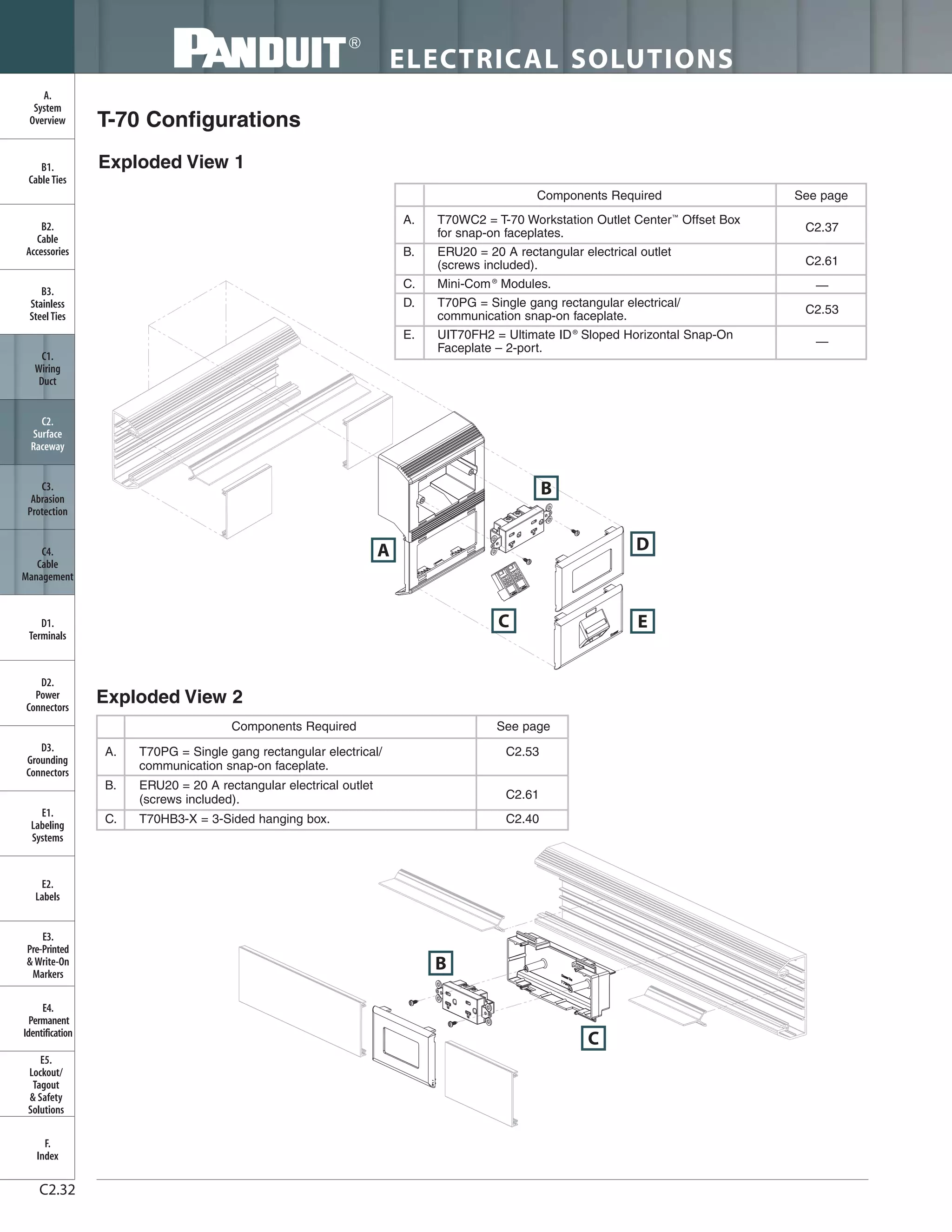


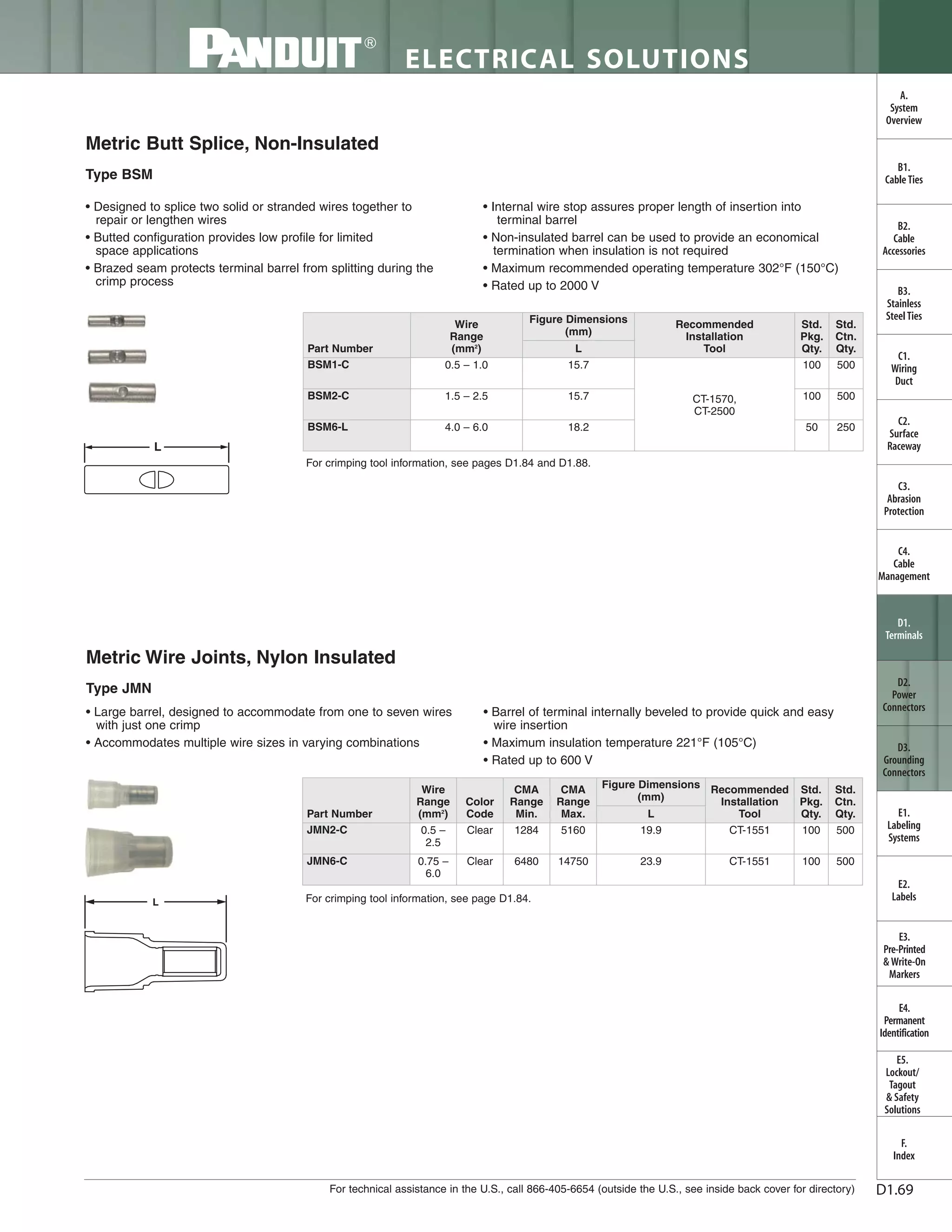


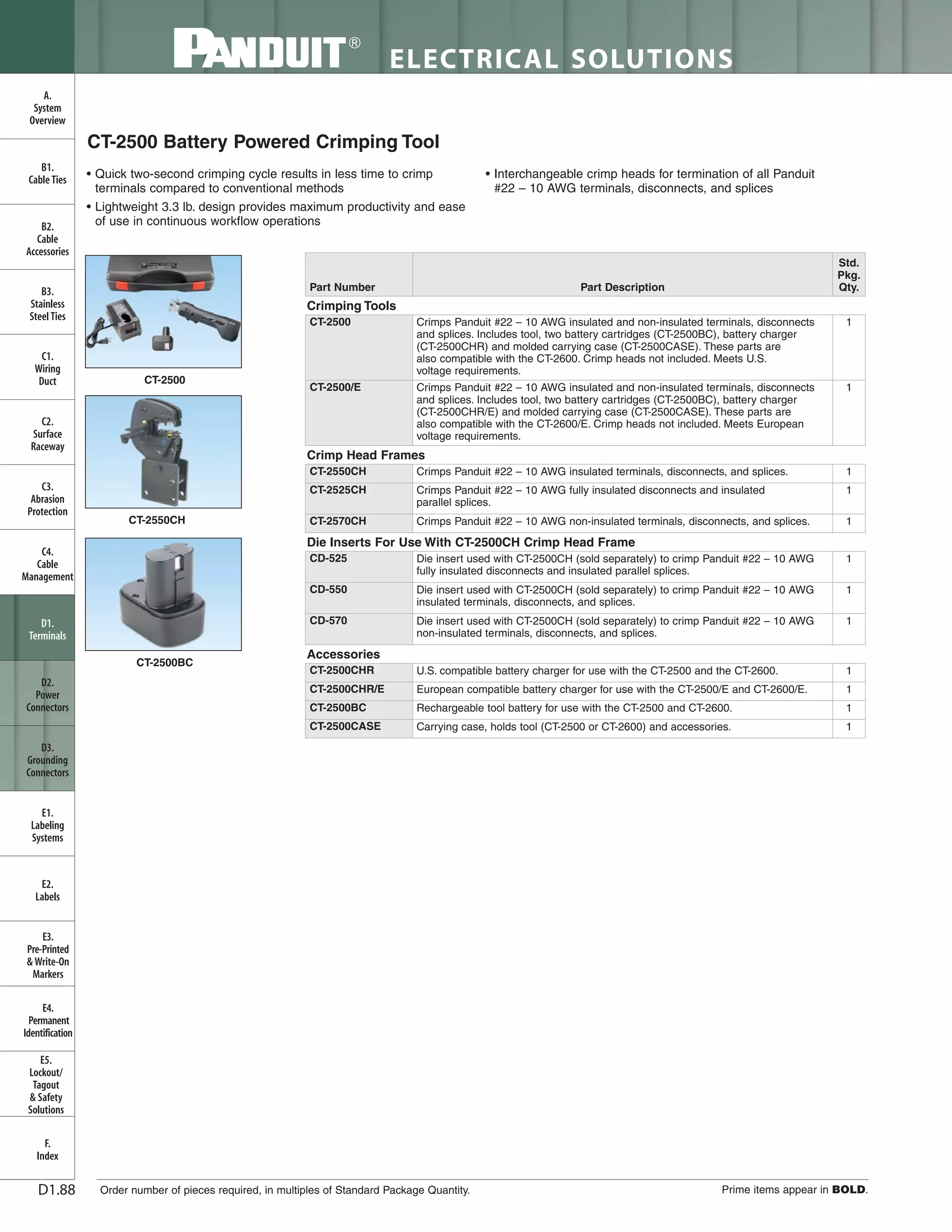


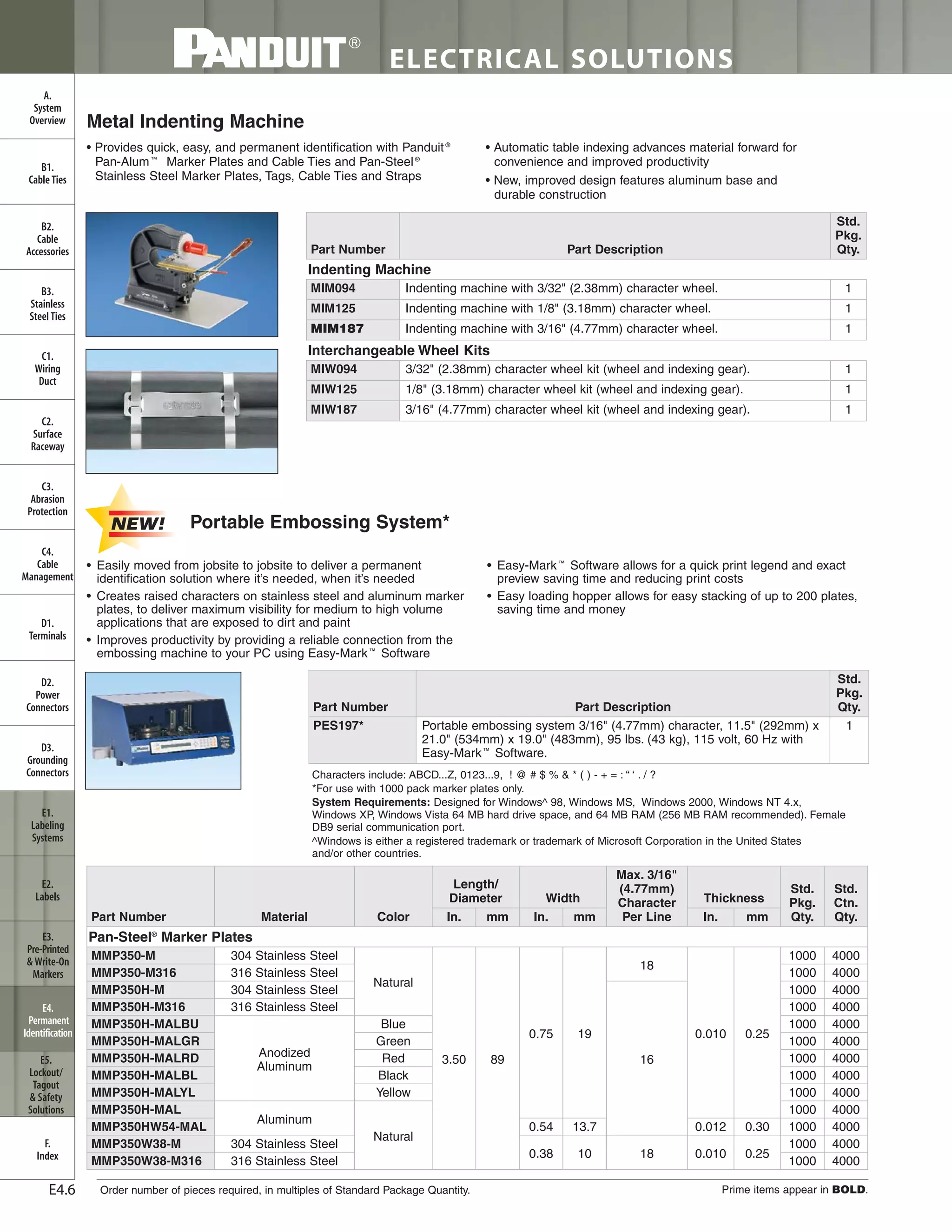


The document is a product catalog for electrical solutions, detailing various cable management systems, wiring ducts, and accessories. It includes sections on cable ties, terminals, power connectors, and identification systems. The catalog highlights new product offerings and provides an index for easy navigation.


