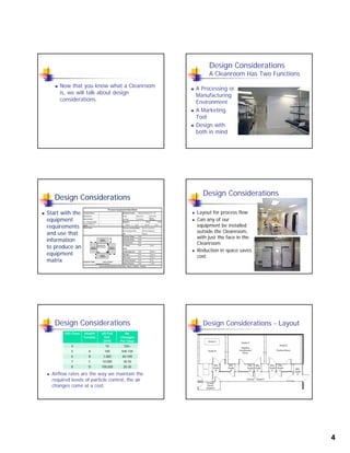
1
Cleanrooms 101
During This Session, We Will:
 Learn - What is a Cleanroom
 Understand how we achieve the Level
of Cleanlinessof Cleanliness.
 Discuss Cleanroom Design.
 Discuss the Certification Process.
What is a Cleanroom?
A specially designed & constructed
room in which; the air supply, air
distribution, filtration of air supply,, pp y,
materials of construction, and operating
procedures, are regulated to control
airborne particle concentrations to meet
appropriate cleanliness
levels.
What is a “Particle”?
 A Particle is a very small discrete mass
of solid or liquid matter, usually
measured in microns.measured in microns.
 A micron is 1/1,000,000 of a metre.
 A human hair is 60 - 90 Microns.
Particle Size Comparison
 An ISO Class 8
Cleanroom will have a
maximum of 70
particles @ 5.0 Micron
and a maximum of
100,000 @ 0.5 Microns
/ Cubic Foot
 (Actually measured in
Cubic Metres in ISO)
Cleanroom Classification
Particles per Cubic Metre
ISO
14644
209E 0.5 Micron 5 Micron
3 1 35 N/A
4 10 352 N/A4 10 352 N/A
5 100 3,520 29
6 1,000 35,200 293
7 10,000 352,000 2,930
8 100,000 3,520,000 29,300
2
Sources of Contamination
Ambient
Equipment
People
Smoking Particle Generation
 A typical smoker is
expelling 10,000 to
20,000 0.03 µM
l
30,000
20,000
10,000
Smoker
Subject stopped smoking
particles 10 minutes
after stopping. A
non smoker
generates less than
1,000.
1 98765432 10 1211
100
2,000
1,000
500
200
5,000
Elapsed Time (Minutes)
Non - Smoker
How do we Control Particles
 Isolation - Particles may be isolated by
containing them at the source of
generation.generation.
 This is difficult as the Processes and
Associates in the Cleanroom are the
Largest Source of Contamination
How are Particles Controlled?
How do we Control Particles?
Fan Powered
H.E.P.A. Filter which
removes 99.99% of
all Particles 0.3
Negative Pressure Plenum
Cooled / Heated /
Humidified &/or
Dehumidified
Secondary Air
 Dilution - Particles
are captured by
filtration, and the
l l
Clean Filtered & Conditioned "Primary Air"
"Dirty" Air Leaving
Cleanroom
all Particles 0.3
Micron
total space volume
is diluted by clean
air
HEPA / ULPA Filters
 This is a Ceiling
Mounted HEPA
Filter.
 High Efficiency
Particulate Air
Filters, range from
99.97% to 99.995%
Efficient
3
ULPA Filters
 These are Ceiling
Mounted ULPA
Filters.
 These High
Efficiency Particulate
Air Filters are
99.9995% Efficient
Return Air Filter Grilles
 This is the
method of
Returning Air
hto the
Negative
Pressure
Plenum
Typical Air Change Rates
ISO Class Health
Canada
US Fed Std.
209E
Air Changes Per
Hour
4 10 720+
5 A 100 500-720
6 B 1,000 60-100
7 C 10,000 30-50
8 D 100,000 20-30
Particle Settling Velocities
Diameter
(m)
Feet / Minute 6’ Drop
0.1 0.0006 7 Days
0.5 0.0020 50 Hours
1.0 0.0069 14.5 Hours
5.0 0.1530 39 Minutes
10 0.602 10 Minutes
100 48.82 7.4 Seconds
Where does Contamination Come From?
 Equipment, Material & Processes in the
Cleanroom produce contamination.
 The largest single controllable source of The largest single controllable source of
contamination enters the Cleanroom
with the Associates that work there.
Associate Contamination
0.5 Micron
Particles /
Minute
Street
Clothing
Bouffant &
Frock
Overall
& Hood
Sitting 302,000 112,000 7,450
Swinging
Arms
2,980,000 300,000 18,700
Twisting
Upper Body
850,000 267,000 14,900
Walking 2,920,000 1,010,000 56,000
4
 Now that you know what a Cleanroom
is, we will talk about design
considerations.considerations.
Design Considerations
A Cleanroom Has Two Functions
 A Processing or
Manufacturing
EnvironmentEnvironment
 A Marketing
Tool
 Design with
both in mind
Design Considerations
 Start with the
equipment
requirementsrequirements
and use that
information
to produce an
equipment
matrix
Design Considerations
 Layout for process flow
 Can any of our
equipment be installedequipment be installed
outside the Cleanroom,
with just the face in the
Cleanroom
 Reduction in space saves
cost.
Design Considerations
ISO Class Health
Canada
US Fed
Std.
209E
Air
Changes
Per Hour
4 10 720+
5 A 100 500-720
 Airflow rates are the way we maintain the
required levels of particle control, the air
changes come at a cost.
5 A 100 500 720
6 B 1,000 60-100
7 C 10,000 30-50
8 D 100,000 20-30
Design Considerations - Layout
5
Design Considerations
 Temperature /
Humidity Ranges have
a large impact on the
HVAC systems
required to maintain
the conditions
required
Design Considerations
 Room or Zone Classifications
 Typically in Pharmaceutical
we look for an Ante Room
between zones with a
differential of 12.5 PA (0.05”
WC) between different
classifications, and 7.5 PA
(0.03” WC) for the same
classification
Design Considerations
 Don’t Skimp on the
size of the Gowning
RoomRoom
 You will require
Storage for garments,
gloves, etc.
 Where will you store
cleaning equipment &
supplies
Design Considerations
 Ceiling height, can be
as low as 8’, however
unless there process
equipment
requirements for
more
height,
9’ is the
normal.
Design Consideration - Walls
 Drywall – Epoxy Painted
 Modular –
Progressive
 Modular – Non
Progressive
Design Consideration - Ceiling
 Drywall
 Gel Seal T BarGel Seal T Bar
 Panel Systems
 T Bar
6
Design Consideration - Floors
 Methyl Methcralate (MMA)
 Epoxy Resins
Urethane Urethane
 Seamless Vinyl
 Vinyl Tile
 Raised Floors
 ESD
Design Consideration - Filtration
 HEPA / ULPA / SULPA
 Terminal
 Room Side Replaceable
 Bubble Tight Dampers
 Duct / AHU Mounted
 Bag In / Bag Out
 Fan Filter Units
Design Consideration – HVAC
 Largest Single Non Process Use of Energy is
in your HVAC, Air Handling, Exhaust & Make
U Ai S tUp Air Systems
 Component Selection is crucial as there are
many factors to a complete “system”.
Consider all component factors.
 Pressure Drop drives fan horsepower.
Design Consideration – Air Handling
 With large amounts of air required for
recirculation, this can be handled by
dedicated air handling systems or by thededicated air handling systems, or by the
use of Fan Filter Units.
Design Consideration - Exhaust
 Exhaust is the largest driver of energy cost,
with our fluctuations in outdoor temperature
we have large winter heating costs, andwe have large winter heating costs, and
Summer conditions that rival the highest in
North America.
Design Consideration – Make Up Air
 Make Up Air required for pressurization or to make
up exhaust is a large component in the system
energy cost.
 To maintain humidity levels
within the controlled space
cooling systems are sized
for full system capacity that
may only be a few hours
per year.
7
Design Consideration - Electrical
Design Consideration -
Process
Design Consideration - Ancillaries
 Air Showers
 Cleaning Materials
 Communication Systems
 Containment
 Gowning
 Pass Through’s
Design Consideration - Portable
Cleanroom:
Testing and Certification
HEPA Filter: High Efficiency Particulate Air Filter
 Rated at 99.97% efficiency minimum
@.3 micron
d d f l Scanned tested HEPA filter is 99.99%
efficiency
 Gasket seal vs. Gel Seal
 Terminal HEPA vs. Ducted HEPA
 Fan Filter Modules
8
High Efficiency Particulate Air Filter
HEPA Housings: Gel Seal vs. Gasket
Primary Tests performed :
 Airflow Volume / Velocity Readings
 HEPA Filter Integrity Testg y
 Room pressure differential readings
 Particle Counts per ISO 14644-1
Airflow Volume / Velocity Readings
Velocity Profiles:
 For non-unidirectional room readings
are taken 6 inches from the supply
source at center of sourcesource at center of source
 For unidirectional rooms readings are
taken 12 inches from the supply
source. Divide the plane into equal
sections and take multiple readings.
 Standard IES-RP-CC-006.3
Air Volume Readings:
 Air volume readings taken to calculate air
changes per hour
Calculation :
Total Diffused Air Supply x 60 Divide by
Room Volume (Cubic Feet) = ACPH
9
Installation tips:
 Ensure ductwork is clean of debris
 Important to not touch HEPA filterp
media
 Do not over tighten clamping system
(gel seal)
 Ensure filter is 99.99% eff. (99.97%)
 Record model, and serial numbers
HEPA Filter Integrity Testing
HEPA Integrity Test
 Introduce aerosol into air system
 Measure upstream concentration to ensure
minimum 10ug/L.g/
 Target upstream is > 20-40ug/L.
 Set photometer for determined upstream
concentration
 Perform scan of filter face with probe at a
scanning rate of 3m/min (10ft per min)
 Maximum repair 5% of area of filter
IES-RP-CC034.2 HEPA
Integrity Test
Room Pressure Differential Readings.
 Correlation between room pressure and
ACPH
 Differential between classes, 0.05” WC
 Magnahelic Gauge & Photohelic
packages and configurations
10
Particle Counts per ISO-14644-1
ISO Class 0.1 um 0.2 um 0.3 um 0.5 um 1 um 5 um
Class 1 10 2
Class 2 100 24 10 4
Class 3 1,000 237 102 35 8
Class 4 10,000 2370 1020 352 83
Class 5 100,000 23700 10200 3520 832 29
Class 6 1,000,000 237,000 102,000 35,200 8320 293
Class 7 352,000 83,200 2930
Class 8 3,520,000 832,000 29,300
Class 9 35,200,000 8,320,000 293,000
Sample Locations
 Determining the number of locations.
 Measure the area under consideration in
square meterssquare meters.
 Calculate the square root of that area.
 Ensure locations are distributed evenly
throughout the area of the Cleanroom
and positioned at the height of the work
activity
Particle Counts per ISO 14644-1
Duct Layout Drawings Additional Systems
11
Cleanroom Standards:
 IEST-RP-CC034.2 HEPA and ULPA Leak Tests
 IEST-RP-CC006.3 Testing Cleanrooms
ISO 14644 1 ISO 14644-1 Classification of air cleanliness
Institute of Environmental Sciences and Technology
2340 S. Arlington Heights Road, Suite 100
Arlington Heights, IL 60005-4516
Phone 847-981-0100 Fax 847-981-4130
Email iest@iest.org
Resources
 IEST - Recommended Practices & ISO
Documents
www.iest.org
 ISPE - Baseline Guides – Communities
of Practice & So much More
www.ispe.org
 ASHRAE – Handbooks
www.ashrae.org
For More Information Contact:
Environmental Systems Corporation
122 Commerce Park Drive, Unit F
Barrie, Ontario, L4N 8W8, Canada
705 722 3220 / 1 866 565 7055
Vernon Solomon – 705 720 0030
vern@e-s-c.ca
David Hislop – 416 953 8691
david@e-s-c.ca
H.E.P.A. FILTER SERVICES INC.
# 4 – 124 Connie Crescent
Concord, ON, L4K 1L7
905 669 1991 / 1 800 669 0037
Bruce Peat
bpeat@hepafilterservices.com
Danny Yee – Montreal - 514 871 9990
Danny.yee@qc.aira.com
Ottawa & Vancouver

Cleanrooms 101

  • 1.
    1 Cleanrooms 101 During ThisSession, We Will:  Learn - What is a Cleanroom  Understand how we achieve the Level of Cleanlinessof Cleanliness.  Discuss Cleanroom Design.  Discuss the Certification Process. What is a Cleanroom? A specially designed & constructed room in which; the air supply, air distribution, filtration of air supply,, pp y, materials of construction, and operating procedures, are regulated to control airborne particle concentrations to meet appropriate cleanliness levels. What is a “Particle”?  A Particle is a very small discrete mass of solid or liquid matter, usually measured in microns.measured in microns.  A micron is 1/1,000,000 of a metre.  A human hair is 60 - 90 Microns. Particle Size Comparison  An ISO Class 8 Cleanroom will have a maximum of 70 particles @ 5.0 Micron and a maximum of 100,000 @ 0.5 Microns / Cubic Foot  (Actually measured in Cubic Metres in ISO) Cleanroom Classification Particles per Cubic Metre ISO 14644 209E 0.5 Micron 5 Micron 3 1 35 N/A 4 10 352 N/A4 10 352 N/A 5 100 3,520 29 6 1,000 35,200 293 7 10,000 352,000 2,930 8 100,000 3,520,000 29,300
  • 2.
    2 Sources of Contamination Ambient Equipment People SmokingParticle Generation  A typical smoker is expelling 10,000 to 20,000 0.03 µM l 30,000 20,000 10,000 Smoker Subject stopped smoking particles 10 minutes after stopping. A non smoker generates less than 1,000. 1 98765432 10 1211 100 2,000 1,000 500 200 5,000 Elapsed Time (Minutes) Non - Smoker How do we Control Particles  Isolation - Particles may be isolated by containing them at the source of generation.generation.  This is difficult as the Processes and Associates in the Cleanroom are the Largest Source of Contamination How are Particles Controlled? How do we Control Particles? Fan Powered H.E.P.A. Filter which removes 99.99% of all Particles 0.3 Negative Pressure Plenum Cooled / Heated / Humidified &/or Dehumidified Secondary Air  Dilution - Particles are captured by filtration, and the l l Clean Filtered & Conditioned "Primary Air" "Dirty" Air Leaving Cleanroom all Particles 0.3 Micron total space volume is diluted by clean air HEPA / ULPA Filters  This is a Ceiling Mounted HEPA Filter.  High Efficiency Particulate Air Filters, range from 99.97% to 99.995% Efficient
  • 3.
    3 ULPA Filters  Theseare Ceiling Mounted ULPA Filters.  These High Efficiency Particulate Air Filters are 99.9995% Efficient Return Air Filter Grilles  This is the method of Returning Air hto the Negative Pressure Plenum Typical Air Change Rates ISO Class Health Canada US Fed Std. 209E Air Changes Per Hour 4 10 720+ 5 A 100 500-720 6 B 1,000 60-100 7 C 10,000 30-50 8 D 100,000 20-30 Particle Settling Velocities Diameter (m) Feet / Minute 6’ Drop 0.1 0.0006 7 Days 0.5 0.0020 50 Hours 1.0 0.0069 14.5 Hours 5.0 0.1530 39 Minutes 10 0.602 10 Minutes 100 48.82 7.4 Seconds Where does Contamination Come From?  Equipment, Material & Processes in the Cleanroom produce contamination.  The largest single controllable source of The largest single controllable source of contamination enters the Cleanroom with the Associates that work there. Associate Contamination 0.5 Micron Particles / Minute Street Clothing Bouffant & Frock Overall & Hood Sitting 302,000 112,000 7,450 Swinging Arms 2,980,000 300,000 18,700 Twisting Upper Body 850,000 267,000 14,900 Walking 2,920,000 1,010,000 56,000
  • 4.
    4  Now thatyou know what a Cleanroom is, we will talk about design considerations.considerations. Design Considerations A Cleanroom Has Two Functions  A Processing or Manufacturing EnvironmentEnvironment  A Marketing Tool  Design with both in mind Design Considerations  Start with the equipment requirementsrequirements and use that information to produce an equipment matrix Design Considerations  Layout for process flow  Can any of our equipment be installedequipment be installed outside the Cleanroom, with just the face in the Cleanroom  Reduction in space saves cost. Design Considerations ISO Class Health Canada US Fed Std. 209E Air Changes Per Hour 4 10 720+ 5 A 100 500-720  Airflow rates are the way we maintain the required levels of particle control, the air changes come at a cost. 5 A 100 500 720 6 B 1,000 60-100 7 C 10,000 30-50 8 D 100,000 20-30 Design Considerations - Layout
  • 5.
    5 Design Considerations  Temperature/ Humidity Ranges have a large impact on the HVAC systems required to maintain the conditions required Design Considerations  Room or Zone Classifications  Typically in Pharmaceutical we look for an Ante Room between zones with a differential of 12.5 PA (0.05” WC) between different classifications, and 7.5 PA (0.03” WC) for the same classification Design Considerations  Don’t Skimp on the size of the Gowning RoomRoom  You will require Storage for garments, gloves, etc.  Where will you store cleaning equipment & supplies Design Considerations  Ceiling height, can be as low as 8’, however unless there process equipment requirements for more height, 9’ is the normal. Design Consideration - Walls  Drywall – Epoxy Painted  Modular – Progressive  Modular – Non Progressive Design Consideration - Ceiling  Drywall  Gel Seal T BarGel Seal T Bar  Panel Systems  T Bar
  • 6.
    6 Design Consideration -Floors  Methyl Methcralate (MMA)  Epoxy Resins Urethane Urethane  Seamless Vinyl  Vinyl Tile  Raised Floors  ESD Design Consideration - Filtration  HEPA / ULPA / SULPA  Terminal  Room Side Replaceable  Bubble Tight Dampers  Duct / AHU Mounted  Bag In / Bag Out  Fan Filter Units Design Consideration – HVAC  Largest Single Non Process Use of Energy is in your HVAC, Air Handling, Exhaust & Make U Ai S tUp Air Systems  Component Selection is crucial as there are many factors to a complete “system”. Consider all component factors.  Pressure Drop drives fan horsepower. Design Consideration – Air Handling  With large amounts of air required for recirculation, this can be handled by dedicated air handling systems or by thededicated air handling systems, or by the use of Fan Filter Units. Design Consideration - Exhaust  Exhaust is the largest driver of energy cost, with our fluctuations in outdoor temperature we have large winter heating costs, andwe have large winter heating costs, and Summer conditions that rival the highest in North America. Design Consideration – Make Up Air  Make Up Air required for pressurization or to make up exhaust is a large component in the system energy cost.  To maintain humidity levels within the controlled space cooling systems are sized for full system capacity that may only be a few hours per year.
  • 7.
    7 Design Consideration -Electrical Design Consideration - Process Design Consideration - Ancillaries  Air Showers  Cleaning Materials  Communication Systems  Containment  Gowning  Pass Through’s Design Consideration - Portable Cleanroom: Testing and Certification HEPA Filter: High Efficiency Particulate Air Filter  Rated at 99.97% efficiency minimum @.3 micron d d f l Scanned tested HEPA filter is 99.99% efficiency  Gasket seal vs. Gel Seal  Terminal HEPA vs. Ducted HEPA  Fan Filter Modules
  • 8.
    8 High Efficiency ParticulateAir Filter HEPA Housings: Gel Seal vs. Gasket Primary Tests performed :  Airflow Volume / Velocity Readings  HEPA Filter Integrity Testg y  Room pressure differential readings  Particle Counts per ISO 14644-1 Airflow Volume / Velocity Readings Velocity Profiles:  For non-unidirectional room readings are taken 6 inches from the supply source at center of sourcesource at center of source  For unidirectional rooms readings are taken 12 inches from the supply source. Divide the plane into equal sections and take multiple readings.  Standard IES-RP-CC-006.3 Air Volume Readings:  Air volume readings taken to calculate air changes per hour Calculation : Total Diffused Air Supply x 60 Divide by Room Volume (Cubic Feet) = ACPH
  • 9.
    9 Installation tips:  Ensureductwork is clean of debris  Important to not touch HEPA filterp media  Do not over tighten clamping system (gel seal)  Ensure filter is 99.99% eff. (99.97%)  Record model, and serial numbers HEPA Filter Integrity Testing HEPA Integrity Test  Introduce aerosol into air system  Measure upstream concentration to ensure minimum 10ug/L.g/  Target upstream is > 20-40ug/L.  Set photometer for determined upstream concentration  Perform scan of filter face with probe at a scanning rate of 3m/min (10ft per min)  Maximum repair 5% of area of filter IES-RP-CC034.2 HEPA Integrity Test Room Pressure Differential Readings.  Correlation between room pressure and ACPH  Differential between classes, 0.05” WC  Magnahelic Gauge & Photohelic packages and configurations
  • 10.
    10 Particle Counts perISO-14644-1 ISO Class 0.1 um 0.2 um 0.3 um 0.5 um 1 um 5 um Class 1 10 2 Class 2 100 24 10 4 Class 3 1,000 237 102 35 8 Class 4 10,000 2370 1020 352 83 Class 5 100,000 23700 10200 3520 832 29 Class 6 1,000,000 237,000 102,000 35,200 8320 293 Class 7 352,000 83,200 2930 Class 8 3,520,000 832,000 29,300 Class 9 35,200,000 8,320,000 293,000 Sample Locations  Determining the number of locations.  Measure the area under consideration in square meterssquare meters.  Calculate the square root of that area.  Ensure locations are distributed evenly throughout the area of the Cleanroom and positioned at the height of the work activity Particle Counts per ISO 14644-1 Duct Layout Drawings Additional Systems
  • 11.
    11 Cleanroom Standards:  IEST-RP-CC034.2HEPA and ULPA Leak Tests  IEST-RP-CC006.3 Testing Cleanrooms ISO 14644 1 ISO 14644-1 Classification of air cleanliness Institute of Environmental Sciences and Technology 2340 S. Arlington Heights Road, Suite 100 Arlington Heights, IL 60005-4516 Phone 847-981-0100 Fax 847-981-4130 Email iest@iest.org Resources  IEST - Recommended Practices & ISO Documents www.iest.org  ISPE - Baseline Guides – Communities of Practice & So much More www.ispe.org  ASHRAE – Handbooks www.ashrae.org For More Information Contact: Environmental Systems Corporation 122 Commerce Park Drive, Unit F Barrie, Ontario, L4N 8W8, Canada 705 722 3220 / 1 866 565 7055 Vernon Solomon – 705 720 0030 vern@e-s-c.ca David Hislop – 416 953 8691 david@e-s-c.ca H.E.P.A. FILTER SERVICES INC. # 4 – 124 Connie Crescent Concord, ON, L4K 1L7 905 669 1991 / 1 800 669 0037 Bruce Peat bpeat@hepafilterservices.com Danny Yee – Montreal - 514 871 9990 Danny.yee@qc.aira.com Ottawa & Vancouver