Downloaded 144 times
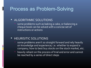
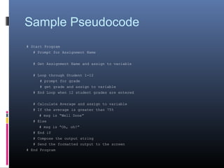
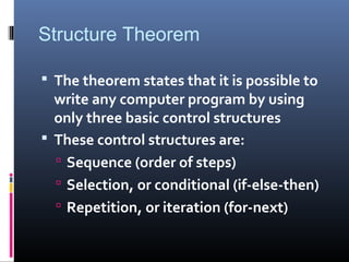
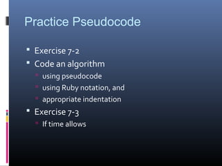
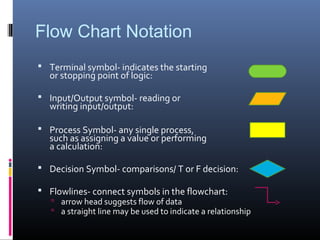
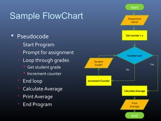
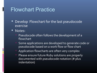

This document covers an introduction to notation, flowcharts, and pseudocode for algorithmic problem solving. It discusses processes, algorithmic solutions, pseudocode structure and syntax, flowchart notation and symbols, and provides examples of pseudocode and a sample flowchart. Students are instructed to practice developing pseudocode and a flowchart to represent an algorithm for calculating student grades and averages.