This is herebyto certify that, the original and
genuine investigation work has been carried out
to investigate about the subject matter and the
related data collection and investigation has been
completed solely, sincerely and satisfactorily by
_______________ of CLASS XII - PCM, _______________
School, ___________ regarding his project titled:
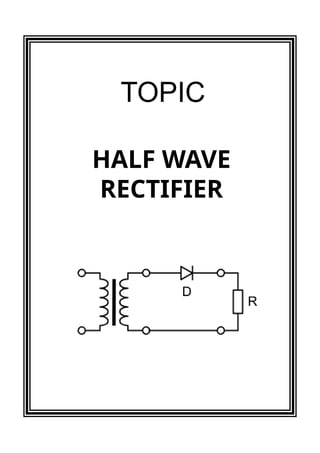
"Half Wave Rectifier”.
CERTIFICATE
_____________________
_________________________
PGT - Physics
_________________School
3.
It would bemy utmost pleasure to express my
sincere thanks to my Physics Teacher
_____________________________ in providing a helping
hand in this project. Their valuable guidance,
support, and supervision all through this project
titled "Half Wave Rectifier", are responsible for
attaining its present form.
ACKNOWLEDGEMENT
________________
Class XII - PCM
____________School
4.
I. Topic
II. Introduction
III.Theory
IV. Experiment
V. Graph
VI. Observation & Calculations
VII. Result & Conclusion
VIII.Applications
IX. Precautions
X. Bibliography
CONTENTS
A rectifier isa simple diode or a group of diodes
which converts the Alternating Current (AC) into
Direct Current (DC).
We know that a diode allows electric current in
one direction and blocks electric current in
another direction. We are using this principle to
construct various types of rectifiers.
Rectifiers are classified into different types based
on the number of diodes used in the circuit or
arrangement of diodes in the circuit. The basic
types of rectifiers are: full wave rectifier and half
wave rectifier.
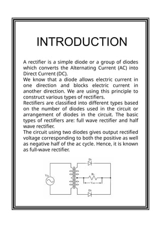
The circuit using two diodes gives output rectified
voltage corresponding to both the positive as well
as negative half of the ac cycle. Hence, it is known
as full-wave rectifier.
INTRODUCTION
7.
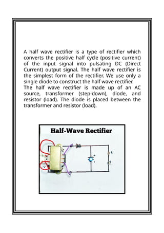
A half waverectifier is a type of rectifier which
converts the positive half cycle (positive current)
of the input signal into pulsating DC (Direct
Current) output signal. The half wave rectifier is
the simplest form of the rectifier. We use only a
single diode to construct the half wave rectifier.
The half wave rectifier is made up of an AC
source, transformer (step-down), diode, and
resistor (load). The diode is placed between the
transformer and resistor (load).
8.
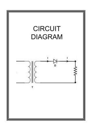
The half-wave rectifiercircuit is made by using a
semiconductor diode (D) with a load resistance.
The diode is connected in series with the
secondary of the transformer and the load
resistance. The primary of the transformer is
being connected to the ac supply mains.
The ac voltage across the secondary winding
changes polarities after every half cycle of input
wave. During the positive half-cycles of the input
ac voltage i.e. when upper end of the secondary
winding is positive with respect to its lower end,
the diode is forward biased and therefore
conducts current. If the forward resistance of the
diode is assumed to be zero (in practice, however,
a small resistance exists) the input voltage during
the positive half-cycles is directly applied to the
load resistance, making its upper end positive with
respect to its lower end. The waveforms of the
output current and output voltage are of the same
shape as that of the input ac voltage.
THEORY
9.
During the negativehalf cycles of the input ac
voltage i.e. when the lower end of the secondary
winding is positive with respect to its upper end,
the diode is reverse biased and so does not
conduct. Thus, during the negative half cycles of
the input ac voltage, the current through and
voltage across the load remains zero. The reverse
current, being very small in magnitude, is
neglected. Thus, for the negative half cycles no
power is delivered to the load.
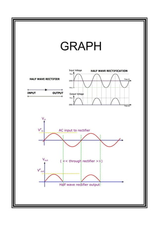
Thus, the output voltage (VL) developed across
load resistance R is a series of positive half cycles
of alternating voltage, with intervening very small
constant negative voltage levels, It is obvious from
the figure that the output is not a steady dc, but
only a pulsating dc wave. To make the output
wave smooth and useful in a DC power supply, we
have to use a filter across the load. Since only half-
cycles of the input wave are used, it is called a half
wave rectifier.
10.
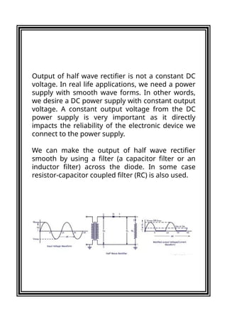
Output of halfwave rectifier is not a constant DC
voltage. In real life applications, we need a power
supply with smooth wave forms. In other words,
we desire a DC power supply with constant output
voltage. A constant output voltage from the DC
power supply is very important as it directly
impacts the reliability of the electronic device we
connect to the power supply.
We can make the output of half wave rectifier
smooth by using a filter (a capacitor filter or an
inductor filter) across the diode. In some case
resistor-capacitor coupled filter (RC) is also used.
11.
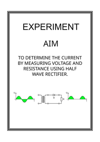
TO DETERMINE THECURRENT
BY MEASURING VOLTAGE AND
RESISTANCE USING HALF
WAVE RECTIFIER.
AIM
EXPERIMENT
12.
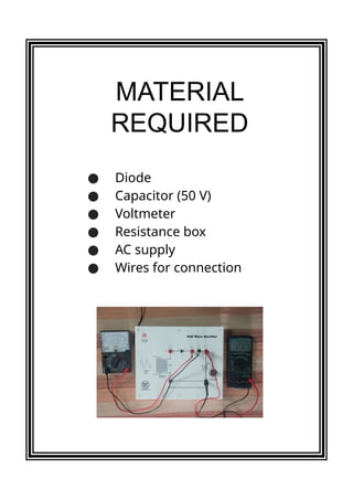
● Diode
● Capacitor(50 V)
● Voltmeter
● Resistance box
● AC supply
● Wires for connection
MATERIAL
REQUIRED
13.
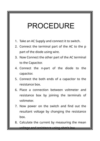
1. Take anAC Supply and connect it to switch.
2. Connect the terminal part of the AC to the p
part of the diode using wire.
3. Now Connect the other part of the AC terminal
to the Capacitor.
4. Connect the n-part of the diode to the
capacitor.
5. Connect the both ends of a capacitor to the
resistance box.
6. Place a connection between voltmeter and
resistance box by joining the terminals of
voltmeter.
7. Now power on the switch and find out the
resultant voltage by changing the resistance
box.
8. Calculate the current by measuring the mean
voltage and resistance using ohm’s law.
PROCEDURE
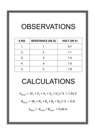
The average currentproduced by Half-wave
rectifier is 0.44 Ampere.
A half wave rectifier is rarely used in practice. It is
never preferred as the power supply of an audio
circuit because of the very high ripple factor. High
ripple factor will result in noises in input audio
signal, which in turn will affect audio quality.
Advantage of a half wave rectifier is only that its
cheap, simple and easy to construct. It is cheap
because of the low number of components
involved. Simple because of the straight
forwardness in circuit design.
Measuring the mean current flow helps us to
understand the amount of AC current passed
through the circuit.
RESULT
CONCLUSION
18.
In day-to-day life,the half-wave rectifier is mostly
used in low power applications because of its
major disadvantage being the output amplitude
which is less than the input amplitude. Thus,
power is wasted and output is pulsated DC
resulting in excessive ripple.
Some of the uses and applications of rectifiers
are in:
● Appliances
● Used with transformers
● Soldering
● AM radio
● Pulse generated circuits
● Single demodulation
● Voltage multiplier
APPLICATIONS
19.
ADVANTAGES
1. Simple circuitwith a smaller number of
components.
2. Economical at initial state. Although there is a
higher cost over time due to more power
losses.
DISADVANTAGES
ADVANTAGES &
DISADVANTAGES
1. Converts only one cycle of the sinusoidal
input given to it and the other cycle gets
wasted. Thus, giving more power loss.
2. Half-Wave rectifier produces lower output
voltage.
3. The output current thus obtained is not
purely DC and it still contains a lot of ripple
(i.e. it has a high ripple factor).
20.
1. Do notswitch on the circuit before checking
whether it is correct or not.
2. The connection between voltmeter and
resistance box should be made correctly.
3. Connect all the wires properly. Loose
connection may end up in failure of circuit.
4. Capacitor of less voltage may be connected to
the diode.
5. Diode should be connected in forward bias.
PRECAUTIONS