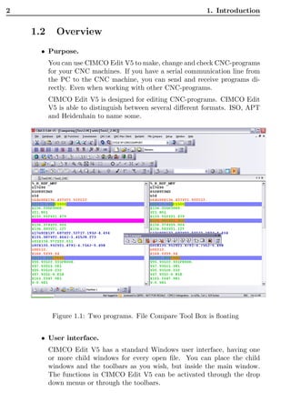
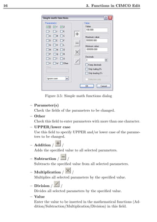
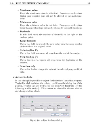
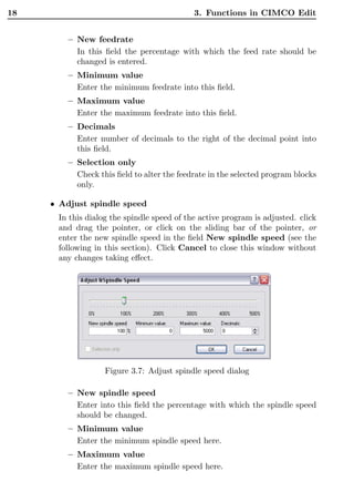
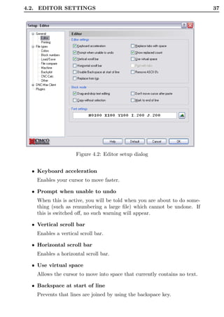
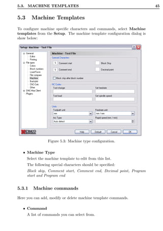
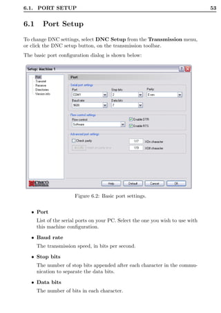
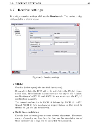
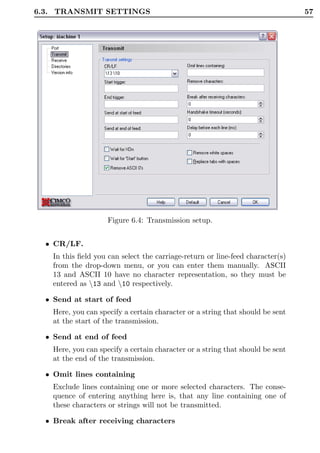
CIMCO Edit V5 User Guide


 c 1991 - 2003 CIMCO Integration – April 15, 2005
II
CONTENTS                                                                                                                III


Contents

1 Introduction                                                                                                     1
  1.1 What is new in this version ofCIMCO Edit V5 . . . . . . . .                                                  1
  1.2 Overview . . . . . . . . . . . . . . . . . . . . . . . . . . . . .                                           2
  1.3 License information . . . . . . . . . . . . . . . . . . . . . . . .                                          5

2 Installation                                                                                                      9

3 Functions in CIMCO Edit                                                                                          11
  3.1 The File menu . . . . . . . . . . . . . . .                      . . . . . . .               .   .   .   .   11
  3.2 The Edit menu . . . . . . . . . . . . . . .                      . . . . . . .               .   .   .   .   12
  3.3 The NC Functions menu . . . . . . . . . .                        . . . . . . .               .   .   .   .   14
  3.4 The Transmission menu . . . . . . . . . .                        . . . . . . .               .   .   .   .   23
  3.5 The File compare menu . . . . . . . . . .                        . . . . . . .               .   .   .   .   24
  3.6 Backplot Turning . . . . . . . . . . . . . .                     . . . . . . .               .   .   .   .   25
  3.7 Backplot Milling . . . . . . . . . . . . . .                     . . . . . . .               .   .   .   .   29
  3.8 The Setup menu . . . . . . . . . . . . . .                       . . . . . . .               .   .   .   .   32
       3.8.1 Menu items for setting up Machine                         Templates .                 .   .   .   .   32
       3.8.2 Menu items for toolbar behavior .                         . . . . . . .               .   .   .   .   33
  3.9 The Window menu . . . . . . . . . . . . .                        . . . . . . .               .   .   .   .   33
  3.10 The Help menu . . . . . . . . . . . . . . .                     . . . . . . .               .   .   .   .   33

4 Editor Setup general                                                                                             35
  4.1 General Program Settings . . . . . . . . . . . . . . . . . . . .                                             35
  4.2 Editor settings . . . . . . . . . . . . . . . . . . . . . . . . . .                                          36
  4.3 Printer setup . . . . . . . . . . . . . . . . . . . . . . . . . . .                                          38

5 Editor Setup File Type                                                                                           41
  5.1 Colors . . . . . . . . . . . .   .   .   .   .   .   .   .   .   .   .   .   .   .   .   .   .   .   .   .   41
  5.2 Block Numbers . . . . . . .      .   .   .   .   .   .   .   .   .   .   .   .   .   .   .   .   .   .   .   43
  5.3 Machine Templates . . . . .      .   .   .   .   .   .   .   .   .   .   .   .   .   .   .   .   .   .   .   45
      5.3.1 Machine commands           .   .   .   .   .   .   .   .   .   .   .   .   .   .   .   .   .   .   .   45
  5.4 Load/Save . . . . . . . . . .    .   .   .   .   .   .   .   .   .   .   .   .   .   .   .   .   .   .   .   47
IV                                                                        CONTENTS


        5.5   File compare settings . . . . . . . . . . . . . . . . . . . . . . .                 48
              5.5.1 Ignore Options. . . . . . . . . . . . . . . . . . . . . . .                   50

     6 DNC settings                                                                               51
       6.1 Port Setup . . . . . . . . . . . . . . . . . . . . . . . . . . . .                     53
       6.2 Receive settings . . . . . . . . . . . . . . . . . . . . . . . . . .                   55
       6.3 Transmit settings . . . . . . . . . . . . . . . . . . . . . . . . .                    56

     7 Serial communication overview                                                              59
       7.1 RS-232 / RS-422 / RS-485 . . . . . . . . . . . .       .   .   .   .   .   .   .   .   59
            7.1.1 RS-232 . . . . . . . . . . . . . . . . . .      .   .   .   .   .   .   .   .   59
            7.1.2 RS-422 . . . . . . . . . . . . . . . . . .      .   .   .   .   .   .   .   .   59
            7.1.3 RS-485 . . . . . . . . . . . . . . . . . .      .   .   .   .   .   .   .   .   60
       7.2 RS-232 layout for 9 pin connector . . . . . . . .      .   .   .   .   .   .   .   .   61
       7.3 RS-232 layout for 25 pin connector . . . . . . .       .   .   .   .   .   .   .   .   61
       7.4 Standard RS-232 serial cable. . . . . . . . . . .      .   .   .   .   .   .   .   .   61
       7.5 How to build a loopback device . . . . . . . . .       .   .   .   .   .   .   .   .   62
            7.5.1 Loopback device for a 9-pin connector .         .   .   .   .   .   .   .   .   62
            7.5.2 Loopback device for a 25-pin connector          .   .   .   .   .   .   .   .   62

     8 Using on-line help                                                                         65
       8.1 Using help in dialogs . . . . . . . . . . . . . . . . . . . . . . .                    65
       8.2 Printing help information . . . . . . . . . . . . . . . . . . . .                      66
LIST OF FIGURES                                                                                                            V


List of Figures

  1.1    Two programs. File Compare Tool Box is floating . . . . . .                                                   2

  2.1    CIMCO Edit V5 setup program. . . . . . . . . . . . . . . . .                                                 9
  2.2    CIMCO Edit V5 . . . . . . . . . . . . . . . . . . . . . . . . .                                              9

  3.1    The file toolbar. . . . . . . . . . .         .   .   .   .   .   .   .   .   .   .   .   .   .   .   .   .   11
  3.2    The editing toolbar. . . . . . . .           .   .   .   .   .   .   .   .   .   .   .   .   .   .   .   .   12
  3.3    Mark/delete dialog box . . . . .             .   .   .   .   .   .   .   .   .   .   .   .   .   .   .   .   13
  3.4    The NC toolbar. . . . . . . . . .            .   .   .   .   .   .   .   .   .   .   .   .   .   .   .   .   14
  3.5    Simple math functions dialog . .             .   .   .   .   .   .   .   .   .   .   .   .   .   .   .   .   16
  3.6    Adjust feedrate dialog . . . . . .           .   .   .   .   .   .   .   .   .   .   .   .   .   .   .   .   17
  3.7    Adjust spindle speed dialog . . .            .   .   .   .   .   .   .   .   .   .   .   .   .   .   .   .   18
  3.8    Rotate Dialog . . . . . . . . . . .          .   .   .   .   .   .   .   .   .   .   .   .   .   .   .   .   19
  3.9    Mirror Dialog . . . . . . . . . . .          .   .   .   .   .   .   .   .   .   .   .   .   .   .   .   .   20
  3.10   Offset/Tool compensation Dialog               .   .   .   .   .   .   .   .   .   .   .   .   .   .   .   .   21
  3.11   Translate Dialog . . . . . . . . .           .   .   .   .   .   .   .   .   .   .   .   .   .   .   .   .   22
  3.12   The DNC send/receive toolbar. .              .   .   .   .   .   .   .   .   .   .   .   .   .   .   .   .   23
  3.13   The File Compare Toolbar. . . .              .   .   .   .   .   .   .   .   .   .   .   .   .   .   .   .   24
  3.14   The Backplot toolbar. . . . . . .            .   .   .   .   .   .   .   .   .   .   .   .   .   .   .   .   25
  3.15   Backplot Konfigurations-Dialog .              .   .   .   .   .   .   .   .   .   .   .   .   .   .   .   .   27
  3.16   The Backplot toolbar. . . . . . .            .   .   .   .   .   .   .   .   .   .   .   .   .   .   .   .   29
  3.17   Backplot Konfigurations-Dialog .              .   .   .   .   .   .   .   .   .   .   .   .   .   .   .   .   30

  4.1    General setup. . . . . . . . . . . . . . . . . . . . . . . . . . .                                           35
  4.2    Editor setup dialog . . . . . . . . . . . . . . . . . . . . . . . .                                          37
  4.3    Printer setup. . . . . . . . . . . . . . . . . . . . . . . . . . . .                                         39

  5.1    Color setup. . . . . . . . . .   .   .   .   .   .   .   .   .   .   .   .   .   .   .   .   .   .   .   .   41
  5.2    Block number configuration.       .   .   .   .   .   .   .   .   .   .   .   .   .   .   .   .   .   .   .   43
  5.3    Machine type configuration.       .   .   .   .   .   .   .   .   .   .   .   .   .   .   .   .   .   .   .   45
  5.4    Load/Save configuration. .        .   .   .   .   .   .   .   .   .   .   .   .   .   .   .   .   .   .   .   47
  5.5    File compare configuration.       .   .   .   .   .   .   .   .   .   .   .   .   .   .   .   .   .   .   .   48
VI                                                                                      LIST OF FIGURES


     6.1   DNC Setup dialog. .      .   .   .   .   .   .   .   .   .   .   .   .   .   .   .   .   .   .   .   .   .   .   .   51
     6.2   Basic port settings. .   .   .   .   .   .   .   .   .   .   .   .   .   .   .   .   .   .   .   .   .   .   .   .   53
     6.3   Receive settings. . .    .   .   .   .   .   .   .   .   .   .   .   .   .   .   .   .   .   .   .   .   .   .   .   55
     6.4   Transmission setup.      .   .   .   .   .   .   .   .   .   .   .   .   .   .   .   .   .   .   .   .   .   .   .   57

     8.1   Click the question mark.         .   .   .   .   .   .   .   .   .   .   .   .   .   .   .   .   .   .   .   .   .   65
     8.2   The question cursor. . .         .   .   .   .   .   .   .   .   .   .   .   .   .   .   .   .   .   .   .   .   .   65
     8.3   The pop-up information.          .   .   .   .   .   .   .   .   .   .   .   .   .   .   .   .   .   .   .   .   .   65
     8.4   Help buttons. . . . . . .        .   .   .   .   .   .   .   .   .   .   .   .   .   .   .   .   .   .   .   .   .   66
LIST OF TABLES                                                                     VII


List of Tables

  7.1   9 pin RS-232 . . . . . . . . . . . . . . . . . . . . . . . . . . .    61
  7.2   25 pin RS-232 . . . . . . . . . . . . . . . . . . . . . . . . . . .   61
  7.3   Standard RS-232 serial cable . . . . . . . . . . . . . . . . . .      62
VIII   LIST OF TABLES
1


Introduction
Congratulations on you purchase of CIMCO Edit V5. CIMCO Edit V5 is the
latest version in a long line of proven CNC editing solutions from CIMCO
Integration.


1.1     What is new in this version ofCIMCO Edit
        V5
CIMCO Edit V5 includes a number of improvements over previous versions.

   • New user interface.
      The new user interface in CIMCO Edit V5 follows the latest standards
      for windows user interface design.
   • Comprehensive on-line help.
      Now everything you need to know about functions that was previously
      contained in the reference manuals is on-line and at your fingertips.
      Stumped on a function? The ? icon, the F1 key, or the Help button
      will take you right to the information you need.
   • Optimized editor engine.
      The new optimized editor engine loads large files quickly, and with
      minimal memory usage.
   • Flexible configuration.
      Flexible configuration of colors, NC commands etc.
   • Advanced standard protocol.
      Advanced standard protocol allows you to communicate with multiple
      CNC’s simultaneously.
2                                                           1. Introduction


    1.2     Overview
      • Purpose.
          You can use CIMCO Edit V5 to make, change and check CNC-programs
          for your CNC machines. If you have a serial communication line from
          the PC to the CNC machine, you can send and receive programs di-
          rectly. Even when working with other CNC-programs.
          CIMCO Edit V5 is designed for editing CNC-programs. CIMCO Edit
          V5 is able to distinguish between several different formats. ISO, APT
          and Heidenhain to name some.


           Figure 1.1: Two programs. File Compare Tool Box is floating


      • User interface.
          CIMCO Edit V5 has a standard Windows user interface, having one
          or more child windows for every open file. You can place the child
          windows and the toolbars as you wish, but inside the main window.
          The functions in CIMCO Edit V5 can be activated through the drop
          down menus or through the toolbars.
1.2. OVERVIEW                                                                3


  • Functions.
   You can undo and redo (almost) all operations you have done since the
   file was opened. You can find the position of a tool change, a spindle
   speed change or feed rate change, or display the range of the X/Y/Z
   axes.
   If you are not sure if two CNC-programs are equal, the File Compare
   functions of CIMCO Edit V5 helps you to pinpoint the differences. The
   File Compare lets you choose two files, and they are put into a two-
   frame window. The differences are shown by coloring the line. You can
   step through the files, stopping at each difference.
   You can customize the colors used to display coordinates and NC com-
   mands, renumber block numbers, and add/remove spaces to increase
   readability, or decrease program size/transmission time.
   The DNC part of CIMCO Edit V5 lets you send and receive CNC-
   programs to your CNC machines in the workshop. The file can be
   sent from a window in CIMCO Edit V5 or directly from the harddisk.
   The file transmission is done while you are working with other CNC
   programs.

  • Setup.
   CIMCO Edit V5 offers you a lot of possibilities for you to control the
   behaviour of the editor. The Setup window is divided into tabs: Gen-
   eral, Editor and Printing.
   In the General tab the appearance of the windows is modified. Further
   you can choose whether a file can be displayed in more than one window
   and if alterations to a file inside CIMCO Edit V5 through another
   program should be indicated.
   You can choose if you want scrollbars or not, and the speed of the
   keyboard can be set in the Editor tab.
   The appearance of the printed CNC-programs is controlled in the Printer
   tab. Define a header and/or a footer. If you have a color printer, you
   might mark the color option.
   CIMCO Edit V5 has 5 different templates for different CNC machines.
   You can setup how the NC functions behave and how the NC code
   appear in the editor window. The Find function in the Edit Menu
   needs a definition of Tool change, Feed rate change etc. This definition
   is made here.

  • Where to find further information.
4                                                        1. Introduction


    In The File menu in the reference manual all CIMCO Edit V5’s func-
    tions are described. A lot of functions can also be accessed through one
    of the toolbars.
    Chapter The Setup menu describes how the behavior of the editor is
    changed.
    The setup of Machine Types is described in Editor Setup File Type.
    If you need help on how to setup a serial communication line you can
    refer to DNC settings and Serial communication overview.
    The On-line help is accessible through the ? icon, the F1 key, or the
    Help button. Chapter The Help menu gives you an introduction to
    the On-line help.
1.3. LICENSE INFORMATION                                                       5


1.3     License information
Information in this document is subject to change without notice and does
not represent a commitment on the part of CIMCO Integration. The software
described in this document may be used or copied only in accordance with
the terms of the license. The purchaser may make one copy of the software
for a backup, but no part of this user manual may be reproduced, stored in
a retrieval system, or transmitted in any form or by any means electronic or
mechanical, including photocopying and recording for any purpose other than
the purchaser’s personal use, without prior written permission from CIMCO
Integration.
6                                                        1. Introduction


         TERMS OF USE FOR SOFTWARE - CIMCO Edit V5

         Date: June 2000
         Copyright 1991-2000 CIMCO Integration
         Software: CIMCO Edit V5 4.x

         Notice:

         CIMCO Integration reserves the right to make improvements
         to the CIMCO Edit V5 Software at any time and without notice.

         Software License

         You have the right to use the number of licenses of the
         enclosed program, which you have bought from CIMCO
         Integration. You may not distribute copies of the program
         or related documentation to any persons or companies. You
         may not modify or translate the program or related
         documentation without the prior written consent of CIMCO
         Integration.

         Disclaimer of all Warranties and Liability

         CIMCO Integration makes no warranties, either express or
         implied, with respect to the software, its quality,
         performance, merchantability, or fitness for any particular
         purpose. The entire risk as to its quality and performance
         is with the buyer. Should the CIMCO Edit software prove
         defective following its purchase, the buyer (and not CIMCO
         Integration, its distributor, or its retailer) assumes the
         entire cost of all necessary servicing, repair, of correction
         and any incidental or consequential damages. In no event will
         CIMCO Integration be liable for direct, indirect, or
         consequential damages resulting from any defect in the
         software, even if CIMCO Integration has been advised of
         the possibility of such damages. Some jurisdictions do not
         allow the exclusion or limitation of implied warranties or
         liability for incidental or consequential damages, so the
         above limitation or exclusion may not apply to you.


    NOTICE: The accompanying software is confidential and proprietary to
    CIMCO Integration. No use or disclosure is permitted other than as ex-
    pressly set forth by written license with CIMCO Integration.
1.3. LICENSE INFORMATION                                                   7


Copyright (c) 1991-2000 CIMCO Integration. All rights reserved.
THIS SOFTWARE CONTAINS CONFIDENTIAL INFORMATION AND
TRADE SECRETS OF CIMCO INTEGRATION. USE, DISCLOSURE, OR
REPRODUCTION IS PROHIBITED WITHOUT THE PRIOR EXPRESS
WRITTEN PERMISSION OF CIMCO INTEGRATION.
DNC-Max, CIMCO Edit, and the CIMCO Logo are trademarks of CIMCO
Integration.
Microsoft, Windows, Win32, Windows NT and are trademarks or registered
trademarks of Microsoft Corporation.
Other brand and product names are trademarks or registered trademarks of
their respective holders.
8   1. Introduction
9


Installation
To install CIMCO Edit V5 follow the instructions below.

  1. Locate installation files.
     If you received CIMCO Edit V5 on a CD-ROM open the CIMCO Edit
     V5 directory on the CD. If you received CIMCO Edit V5 via e-mail,
     save the file in a temporary directory.

  2. Run installation program.
     Start the installation program by clicking on CIMCO Edit V5 setup
     program:


               Figure 2.1: CIMCO Edit V5 setup program.


  3. Copying your keyfile.
     If you do not have a keyfile and wish to install an evaluation version,
     just proceed to the next step.
     If you have received a keyfile, it should be copied to the CIMCOEdit
     directory after the installation is completed.

  4. Starting the editor for the first time.
     When the installation is completed, and you have copied your keyfile,
     you are ready to start the editor for the first time. Click on the CIMCO
     Edit icon on you desktop.


                       Figure 2.2: CIMCO Edit V5


     When the editor is started, verify that your company name is shown in
     the Licensed to field in the about box, if not, you forgot to copy the
     keyfile to the editor directory.
10                                                      2. Installation


     Note: If you are running an evaluation version, the license name is
     Demo version.
11


Functions in CIMCO Edit
The functions in CIMCO Edit V5 are accessible through the dropdown
menus. A lot of the functions in the dropdown menus can also be accessed
from buttons in toolbars. If a function can be executed through a toolbar,
the actual icon will be shown.


3.1     The File menu
In this chapter opening, saving and printing files are described. The functions
are listed in the same order as in the File drop down menu. If the function
can be activated through the File Toolbar or a keyboard shortcut, the icon
or the keystroke will be shown next to the command name.


                        Figure 3.1: The file toolbar.


   • New /       / Ctrl-N
      An empty window will be opened, ready for input. Set the machine
      type for the program by selecting from the list in                     .

   • Open /      / Ctrl-O
      The open file dialog window lets you open an existing program.

   • Close / Ctrl-F4
      Close current window. You will be prompted to save changes if the file
      has been modified.

   • Close All
      Closes all open windows. You will be prompted to save changes for all
      modified files.

   • Save /     / Ctrl-S
      Saves the current CNC-program.
12                                              3. Functions in CIMCO Edit


        • Save As
           Saves the current CNC-program under a new name.

        • Save All /
           Saves all the open CNC-programs under their current names.

        • Print /
           Prints the current CNC-program. This icon is on the Edit toolbar.
           If you want to print a part of a program, mark the area of interest and
           choose Print.

        • Printer Setup
           The dialog window for printout configurations is opened. Please refer
           to The Setup menu.

        • Recent /
           A list of recently used files. Click the down arrow next to the Open
           icon, to open recently used files.

        • Exit / Alt-F4
           Exit CNC-Edit. If there are files open, which have not been saved, you
           will be prompted to save the files.

     noprint002 down


     3.2     The Edit menu
     In this chapter the ordinary text editing functions are described. If the
     function can be activated through the Edit Toolbar or a keyboard shortcut,
     the icon or the keystroke will be shown next to the command name.


                           Figure 3.2: The editing toolbar.


     A part of the text is marked by dragging the cursor from start point to end
     point, while pressing the left mouse button. The background color on the
     marked text is changed to indicate the selected area.
3.2. THE EDIT MENU                                                            13


  • Undo /      / Ctrl-Z
   Undo the last operation.

  • Redo /     / Ctrl-Y
   Redo the last undo operation. You can redo all undo actions performed
   since the file was last opened.

  • Cut /     / Ctrl-X
   Delete the selected text and save it on the clipboard.

  • Copy /     / Ctrl-C
   Copies the selected text to the clipboard.

  • Paste /     / Ctrl-V
   Paste the contents of the clipboard (whatever was cut or copied as
   above) at the current cursor position.

  • Del /     / Del
   Deletes the selected part of the CNC-program.
   To move a part of a program, select the section of the program you
   wish to move, then Cut it, move the cursor and use the Paste function
   described above.

  • Mark/Delete range
   In this dialog window you can specify a range of lines or block numbers,
   to be marked or deleted.


                      Figure 3.3: Mark/delete dialog box


  • Goto line/Block number Ctrl-J
   Jump to block or line number.
14                                                 3. Functions in CIMCO Edit


        • Select all Ctrl-A
           Selects the entire CNC-program.

        • Find       Ctrl-F
           In the appearing dialog box you can specify a text string and search for
           it through the CNC-program. You can choose one of the defined tool
           operations instead of a text string.
        • Find next       F3
           Finds the next occurrence of the specified search string in the CNC-
           program.
        • Find previous         Shift-F3
           Finds the previous occurrence of the specified search string in the CNC-
           program.
        • Replace
           Replaces a specified string in the CNC-program with another string.
           Specify the search string and the substitute string in the dialog box.
        • Insert file
           Inserts a file at the cursor position.
        • Append file
           Appends a file at the end of the current CNC-program.


     3.3     The NC Functions menu
     This chapter describes the functions concerning the appearance of the CNC-
     program. For instance the commands and the block numbers can be changed.
     If the function can be activated through the NC Toolbar an icon is shown
     next to the command name.


                               Figure 3.4: The NC toolbar.

        • Insert block numbers /           / Ctrl-T
           Inserts block numbers in the CNC-program (or renumber the block
           numbers if some already exist in the CNC-program).
3.3. THE NC FUNCTIONS MENU                                                 15


  • Remove block numbers /

   Deletes all block numbers from the CNC-program.


  • Remove Whitespaces /

   Deletes all the space characters and tab signs from the CNC-program
   (whitespace characters).


  • Insert Whitespace /

   Inserts space characters between the commands in the CNC-program,
   where there is no space character between two commands. Existing
   space characters are left as they are.


  • Uppercase

   Changes the case of the text to uppercase.


  • Lowercase

   Changes the case of the text to lowercase.


  • Next Tool change /

   Finds the next tool change in the CNC-program.


  • Previous Tool change /

   Finds the previous tool change in the CNC-program.


  • Find X/Y/Z Ranges

   Finds the highest and lowest values for X, Y, Z, A, B, C, F, and S in
   the CNC-program.


  • Simple math functions

   Performs simple mathematical functions on the chosen NC file parame-
   ters.
16                                     3. Functions in CIMCO Edit


              Figure 3.5: Simple math functions dialog

     – Parameter(s)
       Check the fields of the parameters to be changed.
     – Other
       Check this field to enter parameters with more than one character.
     – UPPER/lower case
       Use this field to specify UPPER and/or lower case of the parame-
       ters to be changed.

     – Addition /      /
       Adds the specified value to all selected parameters.

     – Subtraction /       /
       Subtracts the specified value from all selected parameters.

     – Multiplication /         /
       Multiplies all selected parameters by the specified value.

     – Division /       /
       Divides all selected parameters by the specified value.
     – Value
       Enter the value to be inserted in the mathematical functions (Ad-
       dition/Subtraction/Multiplication/Division) in this field.
3.3. THE NC FUNCTIONS MENU                                                       17


      – Maximum value
        Enter the maximum value in this field. Parameters with values
        higher than specified here will not be altered by the math func-
        tions.
      – Minimum value
        Enter the minimum value in this field. Parameters with values
        lower than specified here will not be altered by the math functions.
      – Decimals
        In this field, enter the number of decimals to the right of the
        decimal point.
      – Keep decimals
        Check this field to provide the new value with the same number
        of decimals as the original value.
      – Strip trailing 0’s
        Check this field to remove all zeros from the end of the number.
      – Strip leading 0’s
        Check this field to remove all zeros from the beginning of the
        number.
      – Selection only
        Check this field to change the value of the selected program block
        only.

  • Adjust feedrate
   In this dialog it is possible to adjust the feedrate of the active program.
   To do this, click and drag the pointer, or click on the sliding bar of the
   pointer, or enter the new feedrate in the field New feedrate (see the
   following in this section). Click cancel to close this window without
   any changes taking effect.


                   Figure 3.6: Adjust feedrate dialog
18                                          3. Functions in CIMCO Edit


         – New feedrate
           In this field the percentage with which the feed rate should be
           changed is entered.
         – Minimum value
           Enter the minimum feedrate into this field.
         – Maximum value
           Enter the maximum feedrate into this field.
         – Decimals
           Enter number of decimals to the right of the decimal point into
           this field.
         – Selection only
           Check this field to alter the feedrate in the selected program blocks
           only.

     • Adjust spindle speed
      In this dialog the spindle speed of the active program is adjusted. click
      and drag the pointer, or click on the sliding bar of the pointer, or
      enter the new spindle speed in the field New spindle speed (see the
      following in this section). Click Cancel to close this window without
      any changes taking effect.


                   Figure 3.7: Adjust spindle speed dialog

         – New spindle speed
           Enter into this field the percentage with which the spindle speed
           should be changed.
         – Minimum value
           Enter the minimum spindle speed here.
         – Maximum value
           Enter the maximum spindle speed here.
3.3. THE NC FUNCTIONS MENU                                                    19


     – Decimals
       Enter the number of decimals to the right of the decimal point
       here.
     – Selection only
       Check this field to change the spindle speed in the selected pro-
       gram blocks only.

  • Rotate
   In this dialog you can rotate the outline around a specified point and
   with a specified angle. Click Cancel to close this window without any
   changes taking effect.


                      Figure 3.8: Rotate Dialog

     – Point (X,Y)
       Enter the co-ordinates of the center of the rotation in these fields.
     – Angle
       Enter the angle of rotation by degrees in this field.
     – ARC type
       Specifies the arc type. You can choose between Auto detect,
       Relative to start, Relative to end, and Absolute arc center.
       Auto detect is default.
     – Decimals
       Enter into this field the number of decimals to the right of the
       decimal point.
     – Strip trailing 0’s
       Check this field to remove all zeros from the end of the number.
20                                          3. Functions in CIMCO Edit


        – Comma as decimal symbol
          Check this field to use a comma as a decimal separator.
        – Assume G91
          Check this field when the control is preset for relative co-ordinates.

     • Mirror
      In this dialog you can mirror the outline around a specified line. Click
      Cancel to close this window without any changes taking effect.


                         Figure 3.9: Mirror Dialog

        – Point (X,Y)
          Enter into these fields the co-ordinates of the point of the mirror
          axis .
        – Angle
          Enter into this field the angle of rotation by degrees of the mirror
          axis.
        – ARC type
          Specifies the arc type. You can choose between Auto detect,
          Relative to start, Relative to end, and Absolute arc center.
          Auto detect is default.
        – Decimals
          Enter into this field the number of decimals to the right of the
          decimal point.
        – Strip trailing 0’s
          Check this field to remove all zeros from the end of the number.
3.3. THE NC FUNCTIONS MENU                                                     21


     – Comma as decimal symbol
       Check this field to use a comma as a decimal separator.
     – Assume G91
       Check this field when the control is preset for relative co-ordinates.

  • Offset/Tool compensation
   In this dialog you can define a tool compensation for the active program
   (offset left G41, offset right G42).


            Figure 3.10: Offset/Tool compensation Dialog

     – Offset
       Enter the offset value into this field.
     – Offset Left (G41)
       Enables compensation of the milling path, offset left (G41).
     – Offset right (G42)
       Enables compensation of the milling path, offset right (G42).
     – ARC type
       Specifies the arc type. You can choose between Auto detect,
       Relative to start, Relative to end, and Absolute arc center.
       Auto detect is default.
     – Decimals
       Enter into this field the number of decimals to the right of the
       decimal point.
     – Strip trailing 0’s
       Check this field to remove all zeros from the end of the number.
22                                           3. Functions in CIMCO Edit


         – Comma as decimal symbol
           Check this field to use a comma as a decimal separator.
         – Assume G91
           Check this field when the control is preset for relative co-ordinates.

     • Translate
      This dialog translates the outline. The outline is moved to a position
      offset by the values entered in the Translate (X,Y,Z) fields.


                        Figure 3.11: Translate Dialog

         – Translate (X,Y,Z)
           Enter into these fields the X, Y, and Z values to offset the outline.
         – ARC type
           Specifies the arc type. You can choose between Auto detect,
           Relative to start, Relative to end, and Absolute arc center.
           Auto detect is default.
         – Decimals
           Enter into this field the number of decimals to the right of the
           decimal point.
         – Strip trailing 0’s
           Check this field to remove all zeros from the end of the number.
         – Comma as decimal symbol
           Check this field to use a comma as a decimal separator.
         – Assume G91
           Check this field when the control is preset for relative co-ordinates.
3.4. THE TRANSMISSION MENU                                                   23


   • Convert Heidenhain to ISO
      Converts 3D Heidenhain Programs to ISO-Programs.
   • Stop a long operation /
      Stops a long operation, such as renumbering a large file.


3.4     The Transmission menu
In this chapter the functions related to sending files to and from CNC-
machines are described. The functions are reachable through the Trans-
mission toolbar. The toolbar is shown below, and every icon is showed next
to the command name.


                Figure 3.12: The DNC send/receive toolbar.


Note: The editor must be licensed for DNC operations to use this toolbar.

   • Send /
      Transmits the current CNC-program to a selected machine.
   • Receive /
      Receives a CNC-program from a selected machine, opening it in a new
      window.
   • Receive into current window /
      Receives a CNC-program into the current window.
   • Send File /
      Transmits a file to a selected machine.
   • Receive File /
      Receives a CNC-program from a selected machine, saving it as a file.
   • Status /
      List the status of current transmissions and/or receptions.
   • DNC Setup /
      Configures the DNC settings in CNC-Edit.
24                                                 3. Functions in CIMCO Edit


     3.5     The File compare menu
     In this section the functions used to compare two files are described. You
     start a comparison of two files by choosing the files. The files are put into a
     double framed window, and you can start the search for differences. To exit
     the file compare window use the End File Compare menu item or button        .
     The functions can be activated through the Transmission toolbar. Some
     functions have a keyboard shortcut. The icons and the keystrokes are shown
     next to the command name.


                       Figure 3.13: The File Compare Toolbar.


     Note: The editor must be licensed for file compare to use this toolbar.

        • Next difference /         / Ctrl-down
           Find the next difference.

        • Previous difference /         / Ctrl-up
           Go to the previous difference.

        • Synchronize left to right /        / Ctrl-right
           Synchronize current difference from the left to the right.

        • Synchronize right to left /        / Ctrl-left
           Synchronize current difference from the right to the left.

        • Goto first difference /
           Go to first difference.

        • Goto last difference /
           Go to last difference.

        • Compare with Window /
           Compare the file in the current window with a file in another.

        • Compare with File /
           Compare the file in the current window with a file. The other file is
           opened through the open file dialog.
3.6. BACKPLOT TURNING                                                             25


   • Compare File with File /
      Compare two files which are not already in a window. The files are
      opened using the open dialog.

   • Setup /
      The behavior of the File Compare functions are changed through the
      Machine Type settings.
      To use single step through differences mark the ’Single line step’ option.

   • Stopping file compare /
      The File compare session is stopped and both files are left open.


3.6     Backplot Turning

This section describes the optional 3D/2D backplot function.
In the following, when the function can be executed both from the toolbar
and a keyboard short cut, the corresponding icon and the key combination
will be shown next to command. The backplot session is terminated by a
click on the    button.
All functions can be executed from the toolbar. Some functions also have
keyboard short cuts. Icons and short cuts are shown next to the command.


                     Figure 3.14: The Backplot toolbar.


Notice: You need a backplot enabled licence key to use this function.


   • Backplot window /
      Splits the window in two, allowing the lines of the program file and
      their toolpath simulation to be shown simultaneously. This icon is
      active only when a program file is already present.

   • Backplot file /
      Opens up a back plot window from an existing file without showing the
      program.
26                                          3. Functions in CIMCO Edit


     • Rotate view /
      Click on this icon to rotate the view in any direction using click and
      drag directly on the image.

     • Zoom view /
      Click on this icon to zoom in and out, using click and drag.

     • Pan view /
      Click on this icon to be able to move the image across the window with
      click and drag.

     • View reset /
      Click on this icon for the default perspective view.

     • View from top (XY/G17) /
      Click on this icon to view the simulation from the top.

     • View from front (YZ/G19) /
      Click on this icon to view the simulation from the front.

     • View from left /
      Click on this icon to view the simulation from the left.

     • Show rapid moves /
      Shows the paths of the tool when in rapid traverse.

     • View arcs /
      Highlights arcs so that they stand out from the straight lines.

     • Show tool /
      Toggles the tool image on and off.

     • Setup /
      This section describes how to configure backplot. The following dialog
      appears:
3.6. BACKPLOT TURNING                                                            27


              Figure 3.15: Backplot Konfigurations-Dialog

  • Turning
   Check this field to configure backplot turning.
  • Diameter programming
   Check this field to select diameter programming.
  • Arc center is specified as diameter
   Check this field to select diameter programming for Arc centers also (I
   coordinate).
  • Show plot as positive X/I
   Check this field to show programs with negative X/I values above the
   Z-Axis line.
  • Arc type
   Check this field if a full circle should be drawn on arcs with the same
   start and end-point.
  • Print Quality
   Use this field to specify the printing quality. Higher quality looks better,
   but requires more time and memory to generate.
28                                          3. Functions in CIMCO Edit


     • Draw ’zero’ arcs
       Check this field if a full circle should be drawn on arcs with the same
       start and end-point.

     • Show cycles
       Check this field to plot cycles.

     • Animation speed


       Controls the speed and direction of the animation play-back: Forward;
       Move control to the right. Back; Move control to the left.

     • Move to start /
       Moves back to the starting point.

     • Move back /
       Back-traces at slow speed.

     • Single step back /
       Goes back one step per click, one step being the equivalent of a program
       line.

     • Pause /
       Stops the animation at the step reached. Animation can be resumed
       by clicking any of the other control buttons.

     • Single step forward /
       Goes forward one step per click, one step being the equivalent of a
       program line.

     • Move forward /
       Starts the animation.

     • Move to end /
       Moves to the end of the program, presenting the static view of the
       complete toolpath.
3.7. BACKPLOT MILLING                                                          29


3.7     Backplot Milling
This section describes the optional 3D/2D backplot function.
In the following, when the function can be executed both from the toolbar
and a keyboard short cut, the corresponding icon and the key combination
will be shown next to command. The backplot session is terminated by a
click on the    button.
All functions can be executed from the toolbar. Some functions also have
keyboard short cuts. Icons and short cuts are shown next to the command.


                     Figure 3.16: The Backplot toolbar.


Notice: You need a backplot enabled licence key to use this function.

   • Backplot window /
      Splits the window in two, allowing the lines of the program file and
      their toolpath simulation to be shown simultaneously. This icon is
      active only when a program file is already present.
   • Backplot file /
      Opens up a back plot window from an existing file without showing the
      program.
   • Rotate view /
      Click on this icon to rotate the view in any direction using click and
      drag directly on the image.
   • Zoom view /
      Click on this icon to zoom in and out, using click and drag.

   • Pan view /
      Click on this icon to be able to move the image across the window with
      click and drag.
   • View reset /
      Click on this icon for the default perspective view.
   • View from top (XY/G17) /
      Click on this icon to view the simulation from the top.
30                                         3. Functions in CIMCO Edit


     • View from front (YZ/G19) /
      Click on this icon to view the simulation from the front.

     • View from left /
      Click on this icon to view the simulation from the left.

     • Show rapid moves /
      Shows the paths of the tool when in rapid traverse.

     • View arcs /
      Highlights arcs so that they stand out from the straight lines.

     • Show tool /
      Toggles the tool image on and off.

     • Setup /
      This section describes how to configure backplot. The following dialog
      appears:
      :


                 Figure 3.17: Backplot Konfigurations-Dialog
3.7. BACKPLOT MILLING                                                             31


  • Milling
    Check this field to configure backplot Milling.

  • Tool Diameter
    Use this field to specify the tool diameter.It is possible to specify the
    diameter as a fraction. Ex. 1/8.

  • Tool type
    Use this field to specify the tool type.

  • Arc type
    Check this field if a full circle should be drawn on arcs with the same
    start and end-point.

  • Print Quality
    Use this field to specify the printing quality. Higher quality looks better,
    but requires more time and memory to generate.

  • Draw ’zero’ arcs
    Check this field if a full circle should be drawn on arcs with the same
    start and end-point.

  • Show cycles
    Check this field to plot cycles.

  • Animation speed


    Controls the speed and direction of the animation play-back: Forward;
    Move control to the right. Back; Move control to the left.

  • Move to start /
    Moves back to the starting point.

  • Move back /
    Back-traces at slow speed.

  • Single step back /
    Goes back one step per click, one step being the equivalent of a program
    line.
32                                               3. Functions in CIMCO Edit


        • Pause /
           Stops the animation at the step reached. Animation can be resumed
           by clicking any of the other control buttons.
        • Single step forward /
           Goes forward one step per click, one step being the equivalent of a
           program line.
        • Move forward /
           Starts the animation.
        • Move to end /
           Moves to the end of the program, presenting the static view of the
           complete toolpath.


     3.8     The Setup menu
     The setup is described in depth in the chapters The Setup menu and Editor
     Setup File Type.
     Setup menu items for CIMCO Edit in general

        • Global
           Global settings. Please refer to section 4.1 for further information.
        • Editor
           Settings for the editor. Please refer to section 4.2 for further informa-
           tion.


     3.8.1    Menu items for setting up Machine Templates
     There is one set of settings for each machine template. Please refer to section
     5 for further information.

        • Colors
           Color settings, for highlighting specific commands, comments and se-
           lections.
        • Block numbers
           Settings for block numbering in the CNC-program.
        • Machine templates
           Settings for program syntax for the different machine templates.
3.9. THE WINDOW MENU                                                           33


3.8.2    Menu items for toolbar behavior
   • Show Status Bar
      Select, whether the status line is to be visible or not.

   • Show Toolbars
      Select which of the toolbars are to be visible.


3.9     The Window menu
This section describes how the sub-windows containing the CNC-programs
can be arranged.

   • Cascade
      Places the open files in an overlapping cascade in the window.
   • Arrange
      Assembles the icons of the minimized CNC-programs in the lower left
      corner of the window.
   • Tile horizontally
      Places the open files in horizontal editor windows in the program win-
      dow.
   • Tile vertically
      Places the open files in vertical editor windows in the program window.


3.10      The Help menu
The on-line help system is explained in Using on-line help.

   • On-line help / F1
      Open the on-line help file.
   • About
      Show information on CIMCO Edit V5 and CIMCO Integration.
34   3. Functions in CIMCO Edit
35


Editor Setup general
This section describes how to configure general CIMCO Edit settings.


4.1     General Program Settings

If you wish to change the program settings concerning the program in gen-
eral, enter the Setup menu and click on the Global Setup. The general
configuration dialog is shown below:


                        Figure 4.1: General setup.


   • Start maximized
      When this field is checked CIMCO Edit V5 will always start maximized,
      i.e. filling up the whole screen.
36                                                      4. Editor Setup general


        • Remember window position
           When this field is checked, the editor is given the same size and position,
           as the last time the editor was used.

        • Open windows maximized
           When this field is checked, edit windows will be opened maximized.

        • Warning beeps
           Check this field to use warnings beeps (switch this off for silent opera-
           tion).

        • Protect read only files
           Check this field to prevent read only files from being modified or edited.

        • Check external changes
           When this field is checked, the editor will check if a file is modified
           outside the editor.
           If a file is modified outside the editor, you will be notified. And you
           will be asked if you want to reload the file. If you choose to do that,
           any changes made since the last save are lost.

        • Open file multiple times
           Check this field if you want to be able to open the same file in more
           than one window in the editor.

        • Language
           Select the language to be used in menues and dialogs.
           Note: Changing language will not have effect until the program is
           restarted.


     4.2     Editor settings

     By clicking on the Editor in the Setup menu the Editor window will be
     displayed (see below). In this window you can configure the settings for the
     editor.
4.2. EDITOR SETTINGS                                                        37


                     Figure 4.2: Editor setup dialog


  • Keyboard acceleration
    Enables your cursor to move faster.

  • Prompt when unable to undo
    When this is active, you will be told when you are about to do some-
    thing (such as renumbering a large file) which cannot be undone. If
    this is switched off, no such warning will appear.

  • Vertical scroll bar
    Enables a vertical scroll bar.

  • Horizontal scroll bar
    Enables a horizontal scroll bar.

  • Use virtual space
    Allows the cursor to move into space that currently contains no text.

  • Backspace at start of line
    Prevents that lines are joined by using the backspace key.
38                                                      4. Editor Setup general


        • Replace from top

           Any search and replace options will automatically start from the be-
           ginning of the file.


        • Replace tabs with space

           Inserts spaces when the tab key is used, and replaces existing tabs with
           spaces when a file is opened.


        • Show replaced count

           Shows the number of strings that were replaced after the replace all
           function has been used.


        • Pad with tabs

           Uses tabs to fill in large empty spaces in virtual space. (Please refer to
           Use virtual space above.)


        • Mark to end of line

           If a whole line is selected, the indication continues across virtual space
           to the side of the window.


        • Copy without selection

           Enables you to copy the line at the cursor, without marking it as a
           selection.


        • Font settings

           Click Select font to change the font used in the editor window.


     4.3     Printer setup

     To change printer settings, choose Printer setup from the File menu. The
     printer configuration dialog is shown below:
4.3. PRINTER SETUP                                                          39


                       Figure 4.3: Printer setup.

  • Syntax highlight
    Use Bold and Italic to highligt NC commands and comments.
  • Use colors
    Enables color printouts. This requires a color printer.
  • Print headers
    Prints headers on every page.
  • Print footers
    Prints footers on every page.
  • Use template
    Applies a pre-defined printer template. A template contains definitions
    of different headers and footers.
  • Raw print
    Produces simple text output to the printer.
  • Send form feed
    Sends a form feed after every printed page.
40                                                      4. Editor Setup general


        • Template
          Select one of the templates from the shown list. A template contains
          definitions of different headers and footers.
        • Printer font
          Select font size and type for the printout.
        • Left margin/Right margin
          Specifies the size of the margins in centimeters. If the margins are in
          inches add ”in”.
          Example:To specify a one-inch margin enter ”1in”.
        • Paper width/ Paper height
          Specifies the size of the paper, in width and height of the paper in
          characters.
        • Header/ footer
          Use these fields to specify the contents of the header and footer.
          The following options are available:

             – %p
               page number
             – %P
               page count
             – %f
               file name
             – %F
               file name with path
             – %t
               time
             – %d
               date
             – %c
               company name

     When clicking on the Print Test button a test page will be printed.
41


Editor Setup File Type
This section describes how to configure file type settings.
File type settings determine how to perform renumbering, look for tool
changes, where to save files etc.


5.1     Colors
To define the colors used for highlighting with a certain machine template,
select Colors from the Setup menu or click on the setup colors . The color
configuration dialog is shown below.


                          Figure 5.1: Color setup.

   • Machine type
      List of different machines templates available.
42                                                    5. Editor Setup File Type


        • Use colors
          Use color highlighting in the file.

        • Use colors in blocks
          Use color highlighting inside a selected block.

        • Text
          The color used for text, when Use colors is not checked.

        • Background
          The background color used for editor windows.

        • Block color
          The background color within a selection.

        • Comments
          The color used for comments, as defined by the Comment start and
          Comment end, or Block Skip character on the Machine template con-
          figuration tab.

        • Value
          The color used for numeric values.

        • Text in blocks
          The color used for text inside a selection, if Use colors in blocks is not
          checked.

        • Letter colors
          Double click on a letter to select a new color.

        • Apply color to trailing letter
          If this option is selected, the selected colors will be applied to any letters
          following the selected letter.

        • Apply color to trailing digits
          If this option is selected, the selected colors will be applied to any digits
          following the selected letter.

     Note: The color settings will only affect the selected machine template,
     unless Apply colors to all machine types is checked at the bottom of the
     window.
5.2. BLOCK NUMBERS                                                                  43


5.2     Block Numbers

To configure renumbering and/or automatic block numbering, select Block
number from the Setup menu, or click the configure block numbering icon
 . The block number configuration dialog is shown below:


                  Figure 5.2: Block number configuration.


   • Machine Type
      Here you select the machine template to edit block numbering for.

   • Auto block numbering
      Inserts line numbers automatically, according to the format described.
      If you make a new line (after the existing lines), the new line number will
      be governed by the preceding line number and the setting for Interval.
      If you insert a line in an existing program, the new line number will be
      midway between the preceding line and the following line.

   • Auto indent lines
      Indents new lines. The indention is set at the same level as the line
      above.
44                                               5. Editor Setup File Type


     • Disable undo prompt for large files
       When this is switched off, you will be told when you are about to
       renumber a large file, which cannot be undone. If this is switched on,
       no such warning will appear.
     • Insert white space after
       Inserts a space character after each block number.
     • Format
       A list of available block number formats. Notice, that this will not
       limit the number of digits in the line number. If you wish to limit the
       number of digits, you have to specify a maximum line number in the
       Restart every field.
     • Start with
       Makes it possible to specify the starting value of the block number.
     • Restart every
       Specifies when the line number must restart. This number is equal to
       the maximum line number.
     • Interval
       Here, you select the interval which the block number must increase by,
       for each block. If you select one of the ’Auto...’ options, the number
       selected is the maximum block number, and the interval will be se-
       lected to distribute the block numbers as evenly as feasible, within this
       maximum block number.
     • From line
       Specifies the first line in the program which will be given a line number.
     • To line
       If a positive number is written here, it specifies the last line to be
       renumbered, counted from the beginning of the program. If a negative
       value (-N) is specified, the last N lines (counted from the end of the
       program) will not be renumbered.
     • Precede lines with
       Enables you to enter a string that will be inserted before the line num-
       ber. For ISO type machines this is normally the letter N.
     • Skip lines starting with
       Defines that the lines starting with a particular string and/or characters
       should be omitted. Multiple strings can be specified using a ’,’ as
       separator. If you wish to omit lines beginning with ’,’, specify with ’,,’.
5.3. MACHINE TEMPLATES                                                  45


5.3     Machine Templates
To configure machine specific characters and commands, select Machine
templates from the Setup. The machine template configuration dialog is
show below:


                  Figure 5.3: Machine type configuration.

   • Machine Type
      Select the machine template to edit from this list.
      The following special characters should be specified:
      Block skip, Comment start, Comment end, Decimal point, Program
      start and Program end


5.3.1    Machine commands

Here you can add, modify or delete machine template commands.

   • Command
      A list of commands you can select from.
46                                                 5. Editor Setup File Type


        • Format
          Specification of string format for the command.
        • Test
          By entering a string you can test the selected command.
          Note: The header changes from Test: Not accepted to Test: Accepted,
          when a string is entered and recognized as a valid command.
        • Add new
          Click this button to add a new command.

        • Delete
          Click this button to delete a command.

     Note: You can not delete the built-in commands.
5.4. LOAD/SAVE                                                                  47


5.4     Load/Save
To configure load/save parameters, select Machine templates from the
Setup menu and click the Load/Save tab. The load/save configuration
dialog is shown below:


                   Figure 5.4: Load/Save configuration.

   • Machine type
      Here you select the machine template to change load/save parameters
      for.
   • Default extension
      Specify a default extension to use. This extension will be appended
      to any new files saved, unless an extension is specified in the ’Save as’
      window
   • Additional extensions
      Define additional file extensions associated with your machine type.

Extensions determines the type(s) of file(s) you wish to open (only files with
the extension(s) defined here will be displayed in an ’Open file’ window). You
can define more than one extension using a comma ’,’ as separator.
48                                                 5. Editor Setup File Type


        • Default load path
           This function specifies the default load path, which is where the file
           open dialog will first point to. If no path is defined the last directory
           you loaded a file from will be used.
           Click on the folder button to browse for an adequate load path.

        • Default save path
           This function specifies the default save path, which is where the file
           save dialog will first point to, when you wish to save a new file of the
           selected type or when you used the file save as menu. If no path is
           defined the last directory you saved a file in will be used.
           Click on the folder button to browse for an adequate save path.


     5.5     File compare settings
     To configure file compare settings, select Setup from the File compare
     menu, or click on the Setup file compare icon on the file compare toolbar.
     The file compare configuration dialog is shown below:


                       Figure 5.5: File compare configuration.
5.5. FILE COMPARE SETTINGS                                                      49


   • Machine type
     Here, you select the machine template you wish to edit the setup for.

   • Single line step
     Highlights only the difference on the current line.

   • Mark Changes only
     Only the difference will be highlighted, not the entire line.

   • Use smart marking
     Not only the different part of the command will be marked, but the
     complete command, if it contains differences.

   • Use fast compare
     Select this option to enable the fast compare feature. When using fast
     compare on large files, it is possible to use the synchronization feature
     without having to re-compare the entire file each time two differences
     are synchronized.

   • Use tab to switch window
     You are able to switch between the two compared files with your tab
     key. Note that when using this feature you cannot insert tabs in any
     of the used files.

   • Jump to the next difference after sync.
     Select this option to enable the fast compare feature. When using fast
     compare on large files, it is possible to use the synchronization feature
     without having to re-compare the entire file each time two differences
     are synchronized.

   • Start at first difference
     The editor will automatically jump to the first difference, when both
     files have been loaded.

Colors are used to indicate differences. You can choose colors by clicking on
one of two buttons shown below. A color chart will then be displayed.
Click the Background for different lines button to select background
color to highlight areas that are different.
Click the Color for missing lines button to select color for the wave line
used to highlight the position of missing lines.
50                                                 5. Editor Setup File Type


     5.5.1   Ignore Options.
        • Ignore Block numbers
          The values of block numbers will be ignored, as will the presence/absence
          of block numbers (i.e. it will be ignored, if there are block numbers in
          one file and not in the other).
        • Ignore White spaces
          White space characters will be ignored. White space characters are
          space (ASCII 32) and tab (ASCII 9).

        • Ignore Comments
          Anything inside a comment will be ignored. For this to work, you
          must have specified the correct ’Comment start’ and ’Comment end’
          characters for this machine template under the ’Machine templates’
          tab.
        • Ignore Case
          It will be ignored, if one program contains lowercase and the other
          UPPERCASE characters.
        • Ignore Numeric format
          Leading and trailing zeros will be ignored, as will optional ’+’ charac-
          ters, i.e. ’X+14.10’ matches ’X14.1’ if this option is used.

     noprint003 down
51


DNC settings
If you wish to configure the settings for communication between the PC and
a selected machine, you can do it in two ways: You can select DNC Setup
from the Transmission menu, select the desired machine, and click Setup.
Or you can select the desired machine in the communications toolbar and
click on the configure DNC icon on the communications toolbar.
If you select DNC Setup from the Transmission menu, this window will
appear:


                      Figure 6.1: DNC Setup dialog.


   • Machine
     If there are several machines connected to the computer, you can select
     which machine to communicate with or configure.

   • Protocol
52                                                       6. DNC settings


      Here, you select the communications protocol for the selected machine.
      Notice that you can not select a protocol which you have no license
      for. If tried, the computer will automatically select the earlier used
      protocol.

     • Port information
      Shows - in shorthand - the most important of the machine settings.
     • Machine Type
      Shows a list of different machines, which can be used as templates.

     • Setup
      Enters the configuration dialog for the selected machine.
     • Delete
      Click this button to delete a configuration.
     • Add new
      Click this button to add a new configuration.
     • Rename
      Click this button to rename a configuration.
6.1. PORT SETUP                                                                  53


6.1     Port Setup
To change DNC settings, select DNC Setup from the Transmission menu,
or click the DNC setup button, on the transmission toolbar.
The basic port configuration dialog is shown below:


                       Figure 6.2: Basic port settings.


   • Port
      List of the serial ports on your PC. Select the one you wish to use with
      this machine configuration.

   • Baud rate
      The transmission speed, in bits per second.

   • Stop bits
      The number of stop bits appended after each character in the commu-
      nication to separate the data bits.

   • Data bits
      The number of bits in each character.
54                                                         6. DNC settings


     • Parity
      An error checking method which indicates if a transmission was suc-
      cessful or not. The method can operate in different modes:
      None. Is selected when no parity error checking is to be used.
      Even parity. An even number of 1’s in each character.
      Odd parity. An odd number of 1’s is used in each character.
      Mark parity. The parity bit is always ’1’ and the line is ’low’.
      Space parity. The parity is always ’0’ and the line is ’high’.

     • Flow control
      The handshake procedure for synchronizing the communication be-
      tween the computer and the control. Software handshake uses the
      XON/XOFF ASCII characters, Hardware handshake uses the RTS/CTS
      control lines in the RS-232 communication specifications.
     • Advanced port settings
      If you want CIMCO Edit V5 to report parity errors, then mark the
      Check parity box. Every time an error occurs the specified character
      is inserted into the file at the receiving point.
      Non standard XOn and XOff characters can be specified.
6.2. RECEIVE SETTINGS                                                        55


6.2     Receive settings
To configure receive settings, click on the Receive tab. The receive config-
uration dialog is shown below:


                        Figure 6.3: Receive settings.


   • CR/LF
      Use this field to specify the line feed character(s).
      If you select Auto, the DNC will try to auto-detect the CR/LF combi-
      nation used. If the remote machine does not use any of the standard
      combinations of ASCII 13 and ASCII 10, you must enter the CR/LF
      combination manually.
      The normal combination is ASCII 13 followed by ASCII 10. ASCII
      13 and ASCII 10 have no character representation, so they must be
      entered as 13 and 10 respectively.

   • Omit lines containing
      Exclude lines containing one or more selected characters. The conse-
      quence of entering anything here is, that any line containing one of
      these characters or strings will be discarded when received.
56                                                             6. DNC settings


        • Remove characters
           Selected characters will automatically be removed from the received
           stream. You can select ’None’, ’ASCII 0’ or ’All below ASCII 32’ from
           the dropdown menu if one of those is appropriate.

        • Start trigger
           Start triggers are characters indicating that CIMCO Edit V5 should
           start saving incoming data. If no start trigger is used and the field
           therefore is left empty, CNC-Edit will start saving at the beginning of
           the file.

        • End trigger
           End triggers are characters indicating that CIMCO Edit V5 should stop
           saving incoming data. If no end trigger is used and the field therefore
           is left empty, CIMCO Edit V5 will continue to save until the end of the
           file, where a timeout occurs.

        • Receive timeout in seconds
           Indicates the time delay after the last character has been received from
           the remote machine, until the computer concludes that the receiving is
           finished. If no end trigger is specified, you should specify a value here,
           or you will have to stop the receive process manually from the receive
           status dialog.

        • Send XOn
           When this field is checked, the DNC will send a XOn character when
           it is ready to receive data.

        • Send at start of reception
           Use this field to specify a string that should be sent to the CNC when
           a receive operation is started.

     Note: When entering characters in one of the character entry fields, the char-
     acters can be entered in two ways. You can enter the characters themselves,
     like $*, or you can enter the ASCII values of the characters, like 3642.($
     has the ASCII code number 36).


     6.3     Transmit settings
     To configure transmit settings, click on the Transmit tab. The transmit
     configuration dialog is shown below:
6.3. TRANSMIT SETTINGS                                                          57


                     Figure 6.4: Transmission setup.


  • CR/LF.
    In this field you can select the carriage-return or line-feed character(s)
    from the drop-down menu, or you can enter them manually. ASCII
    13 and ASCII 10 have no character representation, so they must be
    entered as 13 and 10 respectively.

  • Send at start of feed
    Here, you can specify a certain character or a string that should be sent
    at the start of the transmission.

  • Send at end of feed
    Here, you can specify a certain character or a string that should be sent
    at the end of the transmission.

  • Omit lines containing
    Exclude lines containing one or more selected characters. The conse-
    quence of entering anything here is, that any line containing one of
    these characters or strings will not be transmitted.

  • Break after receiving characters
58                                                             6. DNC settings


          Ends the transmission to the control after a specified number of char-
          acters have been sent, even if the program is not finished. If this field
          is left empty, any incoming characters are ignored.
        • Handshake timeout in seconds
          The chosen time that CIMCO Edit V5 should wait after receiving a stop
          flow signal from a remote machine, before it terminates the connection.
          If the timeout value is not specified, it will wait until a start flow is
          received.
        • Delay before each line in ms
          The time given in milliseconds, CIMCO Edit V5 should wait before it
          begins transmitting a new line.
        • Remove white spaces
          White spaces and tabs are removed automatically from the file trans-
          mitted to the remote machine. This feature is activated with a mark
          in the box.
        • Replace tabs with spaces
          Replaces tabs with spaces before sending the file to the remote machine.
          This feature is activated with a mark in the box.
        • Wait for Xon
          This box is checked if you wish CIMCO Edit V5 to wait for an Xon
          before transmitting data. This option is only available if Software hand-
          shake is enabled in the port settings.

     Note: When entering characters in one of the character entry fields, the char-
     acters can be entered in two ways. You can enter the characters themselves,
     like $*, or you can enter the ASCII values of the characters, like 3642.
59


Serial communication
overview
This section contains information about how to build a standard serial cable,
and loopback device.


7.1     RS-232 / RS-422 / RS-485

7.1.1     RS-232

Quite possibly the most widely used communication standard is RS-232. This
implementation has been defined and revised several times and is often re-
ferred to as RS-232 or EIA/TIA 232. The IBM PC computer defined the
RS-232 port on a 9-pin D sub connector and subsequently the EIA/TIA ap-
proved this implementation as the EIA/TIA 574 standard. This standard is
defined as the 9 Position Non-Synchronous Interface between Data Terminal
Equipment and Data Circuit-Terminating Equipment Employing Serial Bi-
nary Data Interchange. Both implementations are in widespread use and will
be referred to as RS-232 in this document. RS-232 is capable of operating
at data rates up to 20 Kbps at distances less than 50 ft. The absolute max-
imum data rate may vary due to line conditions and cable lengths. RS-232
often operates at 38.4 Kbps over very short distances. The voltage levels
defined by RS-232 range from 12 to +12 volts. RS-232 is a single ended or
unbalanced interface, meaning that a single electrical signal is compared to a
common signal (ground) to determine binary logic states. A voltage of +12
volts (usually +3 to +10 volts) represents a binary 0 (space) and 12 volts (
3 to 10 volts) denotes a binary 1 (mark). The RS-232 and the EIA/TIA-574
specification defines two type of interface circuits, Data Terminal Equipment
(DTE) and Data Circuit-Terminating Equipment (DCE).


7.1.2     RS-422

The RS-422 specification defines the electrical characteristics of balanced
voltage digital interface circuits. RS-422 is a differential interface that defines
voltage levels and driver/receiver electrical specifications. On a differential
60                                          7. Serial communication overview


     interface, logic levels are defined by the difference in voltage between a pair of
     outputs or inputs. In contrast, a single ended interface, for example RS-232,
     defines the logic levels as the difference in voltage between a single signal
     and a common ground connection. Differential interfaces are typically more
     immune to noise or voltage spikes that may occur on the communication
     lines. Differential interfaces also have greater drive capabilities that allow for
     longer cable lengths. RS-422 is rated up to 10 Megabits per second and can
     have cabling 4000 feet long. RS-422 also defines driver and receiver electrical
     characteristics that will allow 1 driver and up to 32 receivers on the line at
     once. RS-422 signal levels range from 0 to +5 volts. RS-422 does not define
     a physical connector.


     7.1.3     RS-485

     RS-485 is backwardly compatible with RS-422; however, it is optimized for
     party line or multi drop applications. The output of the RS-422/485 driver
     is capable of being Active (enabled) or Tri State (disabled). This capability
     allows multiple ports to be connected in a multi drop bus and selectively
     polled. RS-485 allows cable lengths up to 4000 feet and data rates up to
     10 Megabits per second. The signal levels for RS-485 are the same as those
     defined by RS-422. RS-485 has electrical characteristics that allow for 32
     drivers and 32 receivers to be connected to one line. This interface is ideal
     for multi drop or network environments. RS-485 tri state driver (not dual
     state) will allow the electrical presence of the driver to be removed from the
     line. Only one driver may be active at a time and the other driver(s) must
     be tri stated. The output modem control signal RTS controls the state of
     the driver. Some communication software packages refer to RS-485 as RTS
     enable or RTS block mode transfer. RS-485 can be cabled in two ways:
     two wire or four wire mode. Two wire mode does not allow for full duplex
     communication and requires that data be transferred in only one direction at
     a time. For half duplex operation, the two transmit pins should be connected
     to the two receive pins (Tx+ to Rx+ and Tx to Rx ). Four wire mode allows
     full duplex data transfers. RS-485 does not define a connector pin out or a
     set of modem control signals. RS-485 does not define a physical connector.
7.2. RS-232 LAYOUT FOR 9 PIN CONNECTOR                                          61


7.2     RS-232 layout for 9 pin connector

                   P in   Signal                    N ame
                    2     Received Data              RX
                    3     Transmitted Data           TX
                    4     Data Terminal Ready       DTR
                    5     Signal Ground             GND
                    6     Data Set Ready            DSR
                    7     Request To Send            RTS
                    8     Clear To Send             CTS

                          Table 7.1: 9 pin RS-232


Note: Only signals used for regular RS-232 communication are shown.


7.3     RS-232 layout for 25 pin connector

                   P in   Signal                    N ame
                    3     Received Data              RX
                    2     Transmitted Data           TX
                    20    Data Terminal Ready       DTR
                    7     Signal Ground             GND
                    6     Data Set Ready            DSR
                    4     Request To Send            RTS
                    5     Clear To Send             CTS

                          Table 7.2: 25 pin RS-232


Note: Only signals used for regular RS-232 communication are shown.


7.4     Standard RS-232 serial cable.
To build a standard RS-232 serial cable, you will need two 9 or 25 pin female
connectors and a cable with 7 wires, preferably shielded cable.
62                                         7. Serial communication overview


                              ConnectorA     ConnectorB
                                  RX             TX
                                  TX             RX
                                 DTR            DSR
                                 DSR            DTR
                                 RTS            CTS
                                 CTS            RTS
                                 GND            GND

                       Table 7.3: Standard RS-232 serial cable


     If the cable is shielded, you should use the shield as ground (GND).


     7.5     How to build a loopback device
     A loopback is a device that sends the signal back through the same port as
     it is sent out of. It is used for testing purposes and is not used under normal
     operations.
     To make a loopback device, you will need a 9-pin or 25-pin male connector,
     and three pieces of wire.


     7.5.1    Loopback device for a 9-pin connector
        • RX/TX
           Connect pin 2 (RX) to pin 3 (TX).

        • DTR/DSR
           Connect pin 4 (DTR) to pin 6 (DSR).

        • RTS/CTS
           Connect pin 7 (RTS) to pin 8 (CTS).


     7.5.2    Loopback device for a 25-pin connector
        • RX/TX
           Connect pin 3 (RX) to pin 2 (TX).
7.5. HOW TO BUILD A LOOPBACK DEVICE       63


  • DTR/DSR
   Connect pin 20 (DTR) to pin 6 (DSR).
  • RTS/CTS
   Connect pin 4 (RTS) to pin 5 (CTS).
64   7. Serial communication overview
65


Using on-line help
This section describes how to use the on-line help system in CIMCO products.
A standard Windows Help file is available through the dropdown Help menu
or by pressing the F1 key.


8.1     Using help in dialogs
To get help for a particular dialog item, click the ? at the top of a dialog
box, as shown below.


                   Figure 8.1: Click the question mark.

This will change the cursor to an arrow and a question mark indicating that
you are in Help Mode. The new pointer is shown below.


                     Figure 8.2: The question cursor.

Now click on the item that you want further information about. If help is
available for the selected item, a small window will pop up displaying the
help text. If no help is available the general on-line help is launched. An
example of a pop-up help is shown below.


                   Figure 8.3: The pop-up information.

You can also display the pop-up help by pressing F1.
66                                                         8. Using on-line help


     8.2     Printing help information
     If you wish to print just a single section of this on-line help, press the Print
     button on the toolbar (shown below).


                               Figure 8.4: Help buttons.


     If you wish to print more than a few sections, you should open the PDF ver-
     sion of the on-line documentation. The PDF produces a much nicer printout.
     The PDF version is located in the CIMCO Edit V5 Help directory.
     Note: You will need Adobe acrobat reader to open the PDF file.
INDEX                                                                       67


Index

About, 39                            Arrange, 39
Add Current Program, 15              Associate File(s), 15
Add Customer, 18                     Associate files, 64
Add customer, 63                     Associated files location, 70
Add Group, 68                        Assume G91, 28–31
Add new, 84, 90                      Auto Approve, 63
Add new edit programs, 67            Auto block numbering, 81
Add port, 69                         Auto completion, 60
Add Program, 13                      Auto indent lines, 81
Add Programs, 63                     Auto logout time (mins), 60
Add user, 62                         Auto purge, 64, 66
Add/remove columns, 51               Auto unlock, 60
Addition, 25
                                     Background, 80
Additional extensions, 85
                                     Backplot file, 34
Adjust feedrate, 26
                                     Backplot window, 34
Adjust spindle speed, 26
                                     Backspace at start of line, 43
Administrator, 64
                                     Backup, 16, 63
Advanced port settings, 92
                                     Backup associated when unlocking,
Advanced search, 54
                                              66
Allow files outside base directory,
                                     Backup files when unlocking, 66
         65
                                     Base Directory, 75
Allow files outside program direc-
                                     Baud rate, 91
         tory, 65
                                     Block color, 80
Angle, 28, 29
                                     Block numbers, 38
Animation speed, 37                  Break after receiving characters, 95
Append file, 23
Apply color to trailing digits, 80   Cancel, 60, 64, 67, 74, 77, 78
Apply color to trailing letter, 80   Cascade, 39
Approve, 18, 63                      Check external changes, 42
Approved, 55                         Close, 11
Arc CCW (G3), 36                     Close All, 11
Arc CW (G2), 36                      Colors, 38
ARC type, 28–31                      Column order, 52
Arc type, 36                         Comma as decimal symbol, 28–31
68                                                               INDEX


     Command, 83                        Disable setup sheets, 67
     Comments, 80                       Disable tool lists, 66
     Common information, 49             Disable undo prompt for large files,
     Compare, 16, 17                             82
     Compare File with File, 33         Disable user management, 66
     Compare with File, 33              Division, 25
     Compare With Latest Backup, 18     DNC Setup, 32
     Compare with Window, 33            Double click opens program, 58
     Convert Heidenhain to ISO, 31      Double click opens program info,
     Copy, 21                                    58
     Copy without selection, 44         Dynamic Program Preview, 21
     CR/LF, 93
     CR/LF., 95                         Edit, 15, 62
     Customer, 14                       Edit program files, 47
     Cut, 21, 22                        Editor, 38
                                        End trigger, 94
     Data bits, 91                      Exit, 12
     Date, 55                           Explorer, 12
     Decimals, 25–31
     Default, 60, 64, 67, 74, 76, 78    Find, 22
     Default extension, 85              Find Deleted, 20
     Default load path, 86              Find Imported, 20
     Default save path, 86              Find Modified Day, 20
     Del, 22                            Find Modified Week, 20
     Delay before each line in ms, 96   Find next, 22
     Delete, 16, 62, 63, 84, 90         Find previous, 22
     Delete Customer, 19                Find Unlocked, 20
     Delete customer, 63                Find Unproven, 19
     Delete machine group, 68           Find X/Y/Z Ranges, 24
     Deleted, 56                        Flow control, 92
     Disable change columns, 59         Font settings, 44
     Disable column re-arrange, 59      Format, 82, 84
     Disable customer info, 67          From line, 82
     Disable drop files, 59
     Disable editor setup, 59           Global, 38
     Disable external editors, 59       Goto first difference, 33
     Disable file dragging, 59           Goto last difference, 33
     Disable file search, 67             Goto line/Block number, 22
     Disable memo files, 66
     Disable multiple search windows,   Handshake timeout in seconds, 96
              58                        Header/ footer, 46
     Disable other groups, 60           Help, 17, 60, 64, 67, 74, 76, 78
     Disable preview, 59                Horizontal scroll bar, 43
INDEX                                                                   69


Ignore Block numbers, 88           Memo Suffix, 76
Ignore Case, 88                    Memo template, 73
Ignore Comments, 88                Minimum value, 25–27
Ignore Numeric format, 88          Mirror, 28
Ignore White spaces, 88            Modify, 63
Insert block numbers, 23           Modify Customer, 19
Insert file, 23                     Modify customer, 63
Insert white space after, 82       Move back, 37
Insert Whitespace, 23              Move files to program directory, 60
Interval, 82                       Move forward, 37
                                   Move program file to machine di-
Jump to the next difference after            rectory, 14
        sync., 87                  Move to end, 37
                                   Move to start, 37
Keep decimals, 25                  Multiplication, 25
Keep dialogs open, 60
Keyboard acceleration, 43          NC-Base ServerName, 77
                                   New, 11
Language, 42                       New feedrate, 26
Leave copy of program file, 14      New spindle speed, 27
Leave original when moving files,   Next difference, 33
         60                        Next Tool change, 24
Left margin/Right margin, 46
Letter colors, 80                  Offset, 30
Line, 36                           Offset Left (G41), 30
Lock, 18, 63                       Offset right (G42), 30
Locked, 56                         Offset/Tool compensation, 29
Logoff, 20                          OK, 61, 64, 67, 74, 77, 78
Logon, 20                          Omit lines containing, 93, 95
Lowercase, 24                      On-line help, 39
                                   Only backup if changed, 66
Machine, 89                        Open, 11
Machine Group, 14                  Open file multiple times, 42
Machine templates, 38              Open windows maximized, 42
Machine Type, 81, 83, 90           Other, 24
Machine type, 79, 85, 87
Mark Changes only, 87              Pad with tabs, 44
Mark to end of line, 44            Pan view, 34
Mark/Delete range, 22              Paper width/ Paper height, 46
Max number of backups, 67          Parameter(s), 24
Max search results, 60             Parity, 92
Maximum value, 25–27               Paste, 21, 22
Memo File, 14                      Pause, 37
Memo Prefix, 76                     Point (X,Y), 28, 29
70                                                                    INDEX


     Port, 91                                Remove characters, 94
     Port information, 90                    Remove white spaces, 96
     Precede lines with, 82                  Remove Whitespaces, 23
     Preview, 51                             Rename, 69, 90
     Preview associated files, 59             Replace, 23
     Previous difference, 33                  Replace from top, 44
     Previous Tool change, 24                Replace tabs with space, 44
     Print, 12                               Replace tabs with spaces, 96
     Print footers, 45                       Restart every, 82
     Print headers, 45                       Restore, 16, 17, 63
     Printer font, 46                        Restore Latest, 17
     Printer Setup, 12                       Rotate, 27
     Program , 14                            Rotate view, 34
     Program directory, 68
     Program file, 14                         Save, 11
     Program Information, 15                 Save All, 12
     Program search, 49                      Save As, 12
     Program search with customised search   Search for programs, 53
               fields, 50                     Select all, 22
     Programs without a customer, 56         Selection only, 25–27
     Programs without a machine group,       Send, 18, 32, 64
               56                            Send at end of feed, 95
     Prompt when unable to undo, 43          Send at start of feed, 95
     Protect read only files, 42              Send at start of reception, 94
     Protocol, 89                            Send File, 32
     Purge, 17, 64                           Send form feed, 45
     Purge All, 17                           Send XOn, 94
     Purge Backups, 63                       Set associated files ’Read Only’, 66
                                             Set locked files ’Read Only’, 66
     Rapid move, 35                          Set password, 62
     Raw print, 45                           Set-Up Sheet, 14
     Receive, 32, 64                         Setup, 21, 33, 35, 36, 90
     Receive File, 32                        Setup Prefix, 76
     Receive into current window, 32         Setup sheet template, 74
     Receive timeout in seconds, 94          Setup Suffix, 76
     Recent, 12                              Show file path, 59
     Redo, 21                                Show file types, 59
     Reject Imported File, 18                Show preview below results, 59
     Remember last search, 58                Show rapid moves, 35
     Remember password, 58                   Show replaced count, 44
     Remember templates, 60                  Show Status Bar, 38
     Remember window position, 41            Show tool, 35
     Remove block numbers, 23                Show Toolbars, 38
INDEX                                                          71


Simple math functions, 24       Tool list template, 73
Single line step, 87            Tool Prefix, 76
Single step back, 37            Tool Suffix, 76
Single step forward, 37         Tool type, 36
Skip lines starting with, 82    Translate, 30
Start at first difference, 87     Translate (X,Y,Z), 31
Start maximized, 41
Start trigger, 94               Un-delete, 63
Start with, 82                  Undelete, 16
Status, 32                      Undo, 21
Stock, 36                       Unlock, 18, 63
Stop a long operation, 31       UPPER/lower case, 25
Stop bits, 91                   Uppercase, 23
Stopping file compare, 33        Use approval system, 66
Strip leading 0’s, 25           Use CIMCO DNC-Max, 65
Strip trailing 0’s, 25, 28–31   Use colors, 45, 80
Sub-directory, 73               Use colors in blocks, 80
Subtraction, 25                 Use fast compare, 87
Synchronize left to right, 33   Use locking system, 66
Synchronize right to left, 33   Use smart marking, 87
Syntax highlight, 45            Use tab to switch window, 87
                                Use template, 45
Tail, 36                        Use UNC names, 65
Template, 46                    Use virtual space, 43, 44
Test, 84
                                Value, 25, 80
Text, 80
                                Vertical scroll bar, 43
Text field 1, 75
                                View arcs, 35
Text field 2, 75
                                View from front (YZ/G19), 35
Text field 3, 75
                                View from left, 35
Text field 4, 76                 View from top (XY/G17), 34
Text field 5, 76                 View reset, 34
Text field 6, 76
Text field 7, 76                 Wait for Xon, 96
Text field 8, 76                 Warning beeps, 42
Text field 9, 76
Text in blocks, 80              Zoom view, 34
Tile horizontally, 39
Tile vertically, 39
To line, 82
To start NC Base Explorer, 48
Tool Diameter, 36
Tool Length, 36
Tool List, 14
Cimco edit 5 user guide[1]

Cimco edit 5 user guide[1]

  • 2.
    CIMCO Edit V5User Guide c 1991 - 2003 CIMCO Integration – April 15, 2005
  • 3.
  • 4.
    CONTENTS III Contents 1 Introduction 1 1.1 What is new in this version ofCIMCO Edit V5 . . . . . . . . 1 1.2 Overview . . . . . . . . . . . . . . . . . . . . . . . . . . . . . 2 1.3 License information . . . . . . . . . . . . . . . . . . . . . . . . 5 2 Installation 9 3 Functions in CIMCO Edit 11 3.1 The File menu . . . . . . . . . . . . . . . . . . . . . . . . . . 11 3.2 The Edit menu . . . . . . . . . . . . . . . . . . . . . . . . . . 12 3.3 The NC Functions menu . . . . . . . . . . . . . . . . . . . . . 14 3.4 The Transmission menu . . . . . . . . . . . . . . . . . . . . . 23 3.5 The File compare menu . . . . . . . . . . . . . . . . . . . . . 24 3.6 Backplot Turning . . . . . . . . . . . . . . . . . . . . . . . . . 25 3.7 Backplot Milling . . . . . . . . . . . . . . . . . . . . . . . . . 29 3.8 The Setup menu . . . . . . . . . . . . . . . . . . . . . . . . . 32 3.8.1 Menu items for setting up Machine Templates . . . . . 32 3.8.2 Menu items for toolbar behavior . . . . . . . . . . . . 33 3.9 The Window menu . . . . . . . . . . . . . . . . . . . . . . . . 33 3.10 The Help menu . . . . . . . . . . . . . . . . . . . . . . . . . . 33 4 Editor Setup general 35 4.1 General Program Settings . . . . . . . . . . . . . . . . . . . . 35 4.2 Editor settings . . . . . . . . . . . . . . . . . . . . . . . . . . 36 4.3 Printer setup . . . . . . . . . . . . . . . . . . . . . . . . . . . 38 5 Editor Setup File Type 41 5.1 Colors . . . . . . . . . . . . . . . . . . . . . . . . . . . . . . . 41 5.2 Block Numbers . . . . . . . . . . . . . . . . . . . . . . . . . . 43 5.3 Machine Templates . . . . . . . . . . . . . . . . . . . . . . . . 45 5.3.1 Machine commands . . . . . . . . . . . . . . . . . . . 45 5.4 Load/Save . . . . . . . . . . . . . . . . . . . . . . . . . . . . . 47
  • 5.
    IV CONTENTS 5.5 File compare settings . . . . . . . . . . . . . . . . . . . . . . . 48 5.5.1 Ignore Options. . . . . . . . . . . . . . . . . . . . . . . 50 6 DNC settings 51 6.1 Port Setup . . . . . . . . . . . . . . . . . . . . . . . . . . . . 53 6.2 Receive settings . . . . . . . . . . . . . . . . . . . . . . . . . . 55 6.3 Transmit settings . . . . . . . . . . . . . . . . . . . . . . . . . 56 7 Serial communication overview 59 7.1 RS-232 / RS-422 / RS-485 . . . . . . . . . . . . . . . . . . . . 59 7.1.1 RS-232 . . . . . . . . . . . . . . . . . . . . . . . . . . 59 7.1.2 RS-422 . . . . . . . . . . . . . . . . . . . . . . . . . . 59 7.1.3 RS-485 . . . . . . . . . . . . . . . . . . . . . . . . . . 60 7.2 RS-232 layout for 9 pin connector . . . . . . . . . . . . . . . . 61 7.3 RS-232 layout for 25 pin connector . . . . . . . . . . . . . . . 61 7.4 Standard RS-232 serial cable. . . . . . . . . . . . . . . . . . . 61 7.5 How to build a loopback device . . . . . . . . . . . . . . . . . 62 7.5.1 Loopback device for a 9-pin connector . . . . . . . . . 62 7.5.2 Loopback device for a 25-pin connector . . . . . . . . 62 8 Using on-line help 65 8.1 Using help in dialogs . . . . . . . . . . . . . . . . . . . . . . . 65 8.2 Printing help information . . . . . . . . . . . . . . . . . . . . 66
  • 6.
    LIST OF FIGURES V List of Figures 1.1 Two programs. File Compare Tool Box is floating . . . . . . 2 2.1 CIMCO Edit V5 setup program. . . . . . . . . . . . . . . . . 9 2.2 CIMCO Edit V5 . . . . . . . . . . . . . . . . . . . . . . . . . 9 3.1 The file toolbar. . . . . . . . . . . . . . . . . . . . . . . . . . . 11 3.2 The editing toolbar. . . . . . . . . . . . . . . . . . . . . . . . 12 3.3 Mark/delete dialog box . . . . . . . . . . . . . . . . . . . . . 13 3.4 The NC toolbar. . . . . . . . . . . . . . . . . . . . . . . . . . 14 3.5 Simple math functions dialog . . . . . . . . . . . . . . . . . . 16 3.6 Adjust feedrate dialog . . . . . . . . . . . . . . . . . . . . . . 17 3.7 Adjust spindle speed dialog . . . . . . . . . . . . . . . . . . . 18 3.8 Rotate Dialog . . . . . . . . . . . . . . . . . . . . . . . . . . . 19 3.9 Mirror Dialog . . . . . . . . . . . . . . . . . . . . . . . . . . . 20 3.10 Offset/Tool compensation Dialog . . . . . . . . . . . . . . . . 21 3.11 Translate Dialog . . . . . . . . . . . . . . . . . . . . . . . . . 22 3.12 The DNC send/receive toolbar. . . . . . . . . . . . . . . . . . 23 3.13 The File Compare Toolbar. . . . . . . . . . . . . . . . . . . . 24 3.14 The Backplot toolbar. . . . . . . . . . . . . . . . . . . . . . . 25 3.15 Backplot Konfigurations-Dialog . . . . . . . . . . . . . . . . . 27 3.16 The Backplot toolbar. . . . . . . . . . . . . . . . . . . . . . . 29 3.17 Backplot Konfigurations-Dialog . . . . . . . . . . . . . . . . . 30 4.1 General setup. . . . . . . . . . . . . . . . . . . . . . . . . . . 35 4.2 Editor setup dialog . . . . . . . . . . . . . . . . . . . . . . . . 37 4.3 Printer setup. . . . . . . . . . . . . . . . . . . . . . . . . . . . 39 5.1 Color setup. . . . . . . . . . . . . . . . . . . . . . . . . . . . . 41 5.2 Block number configuration. . . . . . . . . . . . . . . . . . . . 43 5.3 Machine type configuration. . . . . . . . . . . . . . . . . . . . 45 5.4 Load/Save configuration. . . . . . . . . . . . . . . . . . . . . 47 5.5 File compare configuration. . . . . . . . . . . . . . . . . . . . 48
  • 7.
    VI LIST OF FIGURES 6.1 DNC Setup dialog. . . . . . . . . . . . . . . . . . . . . . . . . 51 6.2 Basic port settings. . . . . . . . . . . . . . . . . . . . . . . . . 53 6.3 Receive settings. . . . . . . . . . . . . . . . . . . . . . . . . . 55 6.4 Transmission setup. . . . . . . . . . . . . . . . . . . . . . . . 57 8.1 Click the question mark. . . . . . . . . . . . . . . . . . . . . . 65 8.2 The question cursor. . . . . . . . . . . . . . . . . . . . . . . . 65 8.3 The pop-up information. . . . . . . . . . . . . . . . . . . . . . 65 8.4 Help buttons. . . . . . . . . . . . . . . . . . . . . . . . . . . . 66
  • 8.
    LIST OF TABLES VII List of Tables 7.1 9 pin RS-232 . . . . . . . . . . . . . . . . . . . . . . . . . . . 61 7.2 25 pin RS-232 . . . . . . . . . . . . . . . . . . . . . . . . . . . 61 7.3 Standard RS-232 serial cable . . . . . . . . . . . . . . . . . . 62
  • 9.
    VIII LIST OF TABLES
  • 10.
    1 Introduction Congratulations on youpurchase of CIMCO Edit V5. CIMCO Edit V5 is the latest version in a long line of proven CNC editing solutions from CIMCO Integration. 1.1 What is new in this version ofCIMCO Edit V5 CIMCO Edit V5 includes a number of improvements over previous versions. • New user interface. The new user interface in CIMCO Edit V5 follows the latest standards for windows user interface design. • Comprehensive on-line help. Now everything you need to know about functions that was previously contained in the reference manuals is on-line and at your fingertips. Stumped on a function? The ? icon, the F1 key, or the Help button will take you right to the information you need. • Optimized editor engine. The new optimized editor engine loads large files quickly, and with minimal memory usage. • Flexible configuration. Flexible configuration of colors, NC commands etc. • Advanced standard protocol. Advanced standard protocol allows you to communicate with multiple CNC’s simultaneously.
  • 11.
    2 1. Introduction 1.2 Overview • Purpose. You can use CIMCO Edit V5 to make, change and check CNC-programs for your CNC machines. If you have a serial communication line from the PC to the CNC machine, you can send and receive programs di- rectly. Even when working with other CNC-programs. CIMCO Edit V5 is designed for editing CNC-programs. CIMCO Edit V5 is able to distinguish between several different formats. ISO, APT and Heidenhain to name some. Figure 1.1: Two programs. File Compare Tool Box is floating • User interface. CIMCO Edit V5 has a standard Windows user interface, having one or more child windows for every open file. You can place the child windows and the toolbars as you wish, but inside the main window. The functions in CIMCO Edit V5 can be activated through the drop down menus or through the toolbars.
  • 12.
    1.2. OVERVIEW 3 • Functions. You can undo and redo (almost) all operations you have done since the file was opened. You can find the position of a tool change, a spindle speed change or feed rate change, or display the range of the X/Y/Z axes. If you are not sure if two CNC-programs are equal, the File Compare functions of CIMCO Edit V5 helps you to pinpoint the differences. The File Compare lets you choose two files, and they are put into a two- frame window. The differences are shown by coloring the line. You can step through the files, stopping at each difference. You can customize the colors used to display coordinates and NC com- mands, renumber block numbers, and add/remove spaces to increase readability, or decrease program size/transmission time. The DNC part of CIMCO Edit V5 lets you send and receive CNC- programs to your CNC machines in the workshop. The file can be sent from a window in CIMCO Edit V5 or directly from the harddisk. The file transmission is done while you are working with other CNC programs. • Setup. CIMCO Edit V5 offers you a lot of possibilities for you to control the behaviour of the editor. The Setup window is divided into tabs: Gen- eral, Editor and Printing. In the General tab the appearance of the windows is modified. Further you can choose whether a file can be displayed in more than one window and if alterations to a file inside CIMCO Edit V5 through another program should be indicated. You can choose if you want scrollbars or not, and the speed of the keyboard can be set in the Editor tab. The appearance of the printed CNC-programs is controlled in the Printer tab. Define a header and/or a footer. If you have a color printer, you might mark the color option. CIMCO Edit V5 has 5 different templates for different CNC machines. You can setup how the NC functions behave and how the NC code appear in the editor window. The Find function in the Edit Menu needs a definition of Tool change, Feed rate change etc. This definition is made here. • Where to find further information.
  • 13.
    4 1. Introduction In The File menu in the reference manual all CIMCO Edit V5’s func- tions are described. A lot of functions can also be accessed through one of the toolbars. Chapter The Setup menu describes how the behavior of the editor is changed. The setup of Machine Types is described in Editor Setup File Type. If you need help on how to setup a serial communication line you can refer to DNC settings and Serial communication overview. The On-line help is accessible through the ? icon, the F1 key, or the Help button. Chapter The Help menu gives you an introduction to the On-line help.
  • 14.
    1.3. LICENSE INFORMATION 5 1.3 License information Information in this document is subject to change without notice and does not represent a commitment on the part of CIMCO Integration. The software described in this document may be used or copied only in accordance with the terms of the license. The purchaser may make one copy of the software for a backup, but no part of this user manual may be reproduced, stored in a retrieval system, or transmitted in any form or by any means electronic or mechanical, including photocopying and recording for any purpose other than the purchaser’s personal use, without prior written permission from CIMCO Integration.
  • 15.
    6 1. Introduction TERMS OF USE FOR SOFTWARE - CIMCO Edit V5 Date: June 2000 Copyright 1991-2000 CIMCO Integration Software: CIMCO Edit V5 4.x Notice: CIMCO Integration reserves the right to make improvements to the CIMCO Edit V5 Software at any time and without notice. Software License You have the right to use the number of licenses of the enclosed program, which you have bought from CIMCO Integration. You may not distribute copies of the program or related documentation to any persons or companies. You may not modify or translate the program or related documentation without the prior written consent of CIMCO Integration. Disclaimer of all Warranties and Liability CIMCO Integration makes no warranties, either express or implied, with respect to the software, its quality, performance, merchantability, or fitness for any particular purpose. The entire risk as to its quality and performance is with the buyer. Should the CIMCO Edit software prove defective following its purchase, the buyer (and not CIMCO Integration, its distributor, or its retailer) assumes the entire cost of all necessary servicing, repair, of correction and any incidental or consequential damages. In no event will CIMCO Integration be liable for direct, indirect, or consequential damages resulting from any defect in the software, even if CIMCO Integration has been advised of the possibility of such damages. Some jurisdictions do not allow the exclusion or limitation of implied warranties or liability for incidental or consequential damages, so the above limitation or exclusion may not apply to you. NOTICE: The accompanying software is confidential and proprietary to CIMCO Integration. No use or disclosure is permitted other than as ex- pressly set forth by written license with CIMCO Integration.
  • 16.
    1.3. LICENSE INFORMATION 7 Copyright (c) 1991-2000 CIMCO Integration. All rights reserved. THIS SOFTWARE CONTAINS CONFIDENTIAL INFORMATION AND TRADE SECRETS OF CIMCO INTEGRATION. USE, DISCLOSURE, OR REPRODUCTION IS PROHIBITED WITHOUT THE PRIOR EXPRESS WRITTEN PERMISSION OF CIMCO INTEGRATION. DNC-Max, CIMCO Edit, and the CIMCO Logo are trademarks of CIMCO Integration. Microsoft, Windows, Win32, Windows NT and are trademarks or registered trademarks of Microsoft Corporation. Other brand and product names are trademarks or registered trademarks of their respective holders.
  • 17.
    8 1. Introduction
  • 18.
    9 Installation To install CIMCOEdit V5 follow the instructions below. 1. Locate installation files. If you received CIMCO Edit V5 on a CD-ROM open the CIMCO Edit V5 directory on the CD. If you received CIMCO Edit V5 via e-mail, save the file in a temporary directory. 2. Run installation program. Start the installation program by clicking on CIMCO Edit V5 setup program: Figure 2.1: CIMCO Edit V5 setup program. 3. Copying your keyfile. If you do not have a keyfile and wish to install an evaluation version, just proceed to the next step. If you have received a keyfile, it should be copied to the CIMCOEdit directory after the installation is completed. 4. Starting the editor for the first time. When the installation is completed, and you have copied your keyfile, you are ready to start the editor for the first time. Click on the CIMCO Edit icon on you desktop. Figure 2.2: CIMCO Edit V5 When the editor is started, verify that your company name is shown in the Licensed to field in the about box, if not, you forgot to copy the keyfile to the editor directory.
  • 19.
    10 2. Installation Note: If you are running an evaluation version, the license name is Demo version.
  • 20.
    11 Functions in CIMCOEdit The functions in CIMCO Edit V5 are accessible through the dropdown menus. A lot of the functions in the dropdown menus can also be accessed from buttons in toolbars. If a function can be executed through a toolbar, the actual icon will be shown. 3.1 The File menu In this chapter opening, saving and printing files are described. The functions are listed in the same order as in the File drop down menu. If the function can be activated through the File Toolbar or a keyboard shortcut, the icon or the keystroke will be shown next to the command name. Figure 3.1: The file toolbar. • New / / Ctrl-N An empty window will be opened, ready for input. Set the machine type for the program by selecting from the list in . • Open / / Ctrl-O The open file dialog window lets you open an existing program. • Close / Ctrl-F4 Close current window. You will be prompted to save changes if the file has been modified. • Close All Closes all open windows. You will be prompted to save changes for all modified files. • Save / / Ctrl-S Saves the current CNC-program.
  • 21.
    12 3. Functions in CIMCO Edit • Save As Saves the current CNC-program under a new name. • Save All / Saves all the open CNC-programs under their current names. • Print / Prints the current CNC-program. This icon is on the Edit toolbar. If you want to print a part of a program, mark the area of interest and choose Print. • Printer Setup The dialog window for printout configurations is opened. Please refer to The Setup menu. • Recent / A list of recently used files. Click the down arrow next to the Open icon, to open recently used files. • Exit / Alt-F4 Exit CNC-Edit. If there are files open, which have not been saved, you will be prompted to save the files. noprint002 down 3.2 The Edit menu In this chapter the ordinary text editing functions are described. If the function can be activated through the Edit Toolbar or a keyboard shortcut, the icon or the keystroke will be shown next to the command name. Figure 3.2: The editing toolbar. A part of the text is marked by dragging the cursor from start point to end point, while pressing the left mouse button. The background color on the marked text is changed to indicate the selected area.
  • 22.
    3.2. THE EDITMENU 13 • Undo / / Ctrl-Z Undo the last operation. • Redo / / Ctrl-Y Redo the last undo operation. You can redo all undo actions performed since the file was last opened. • Cut / / Ctrl-X Delete the selected text and save it on the clipboard. • Copy / / Ctrl-C Copies the selected text to the clipboard. • Paste / / Ctrl-V Paste the contents of the clipboard (whatever was cut or copied as above) at the current cursor position. • Del / / Del Deletes the selected part of the CNC-program. To move a part of a program, select the section of the program you wish to move, then Cut it, move the cursor and use the Paste function described above. • Mark/Delete range In this dialog window you can specify a range of lines or block numbers, to be marked or deleted. Figure 3.3: Mark/delete dialog box • Goto line/Block number Ctrl-J Jump to block or line number.
  • 23.
    14 3. Functions in CIMCO Edit • Select all Ctrl-A Selects the entire CNC-program. • Find Ctrl-F In the appearing dialog box you can specify a text string and search for it through the CNC-program. You can choose one of the defined tool operations instead of a text string. • Find next F3 Finds the next occurrence of the specified search string in the CNC- program. • Find previous Shift-F3 Finds the previous occurrence of the specified search string in the CNC- program. • Replace Replaces a specified string in the CNC-program with another string. Specify the search string and the substitute string in the dialog box. • Insert file Inserts a file at the cursor position. • Append file Appends a file at the end of the current CNC-program. 3.3 The NC Functions menu This chapter describes the functions concerning the appearance of the CNC- program. For instance the commands and the block numbers can be changed. If the function can be activated through the NC Toolbar an icon is shown next to the command name. Figure 3.4: The NC toolbar. • Insert block numbers / / Ctrl-T Inserts block numbers in the CNC-program (or renumber the block numbers if some already exist in the CNC-program).
  • 24.
    3.3. THE NCFUNCTIONS MENU 15 • Remove block numbers / Deletes all block numbers from the CNC-program. • Remove Whitespaces / Deletes all the space characters and tab signs from the CNC-program (whitespace characters). • Insert Whitespace / Inserts space characters between the commands in the CNC-program, where there is no space character between two commands. Existing space characters are left as they are. • Uppercase Changes the case of the text to uppercase. • Lowercase Changes the case of the text to lowercase. • Next Tool change / Finds the next tool change in the CNC-program. • Previous Tool change / Finds the previous tool change in the CNC-program. • Find X/Y/Z Ranges Finds the highest and lowest values for X, Y, Z, A, B, C, F, and S in the CNC-program. • Simple math functions Performs simple mathematical functions on the chosen NC file parame- ters.
  • 25.
    16 3. Functions in CIMCO Edit Figure 3.5: Simple math functions dialog – Parameter(s) Check the fields of the parameters to be changed. – Other Check this field to enter parameters with more than one character. – UPPER/lower case Use this field to specify UPPER and/or lower case of the parame- ters to be changed. – Addition / / Adds the specified value to all selected parameters. – Subtraction / / Subtracts the specified value from all selected parameters. – Multiplication / / Multiplies all selected parameters by the specified value. – Division / / Divides all selected parameters by the specified value. – Value Enter the value to be inserted in the mathematical functions (Ad- dition/Subtraction/Multiplication/Division) in this field.
  • 26.
    3.3. THE NCFUNCTIONS MENU 17 – Maximum value Enter the maximum value in this field. Parameters with values higher than specified here will not be altered by the math func- tions. – Minimum value Enter the minimum value in this field. Parameters with values lower than specified here will not be altered by the math functions. – Decimals In this field, enter the number of decimals to the right of the decimal point. – Keep decimals Check this field to provide the new value with the same number of decimals as the original value. – Strip trailing 0’s Check this field to remove all zeros from the end of the number. – Strip leading 0’s Check this field to remove all zeros from the beginning of the number. – Selection only Check this field to change the value of the selected program block only. • Adjust feedrate In this dialog it is possible to adjust the feedrate of the active program. To do this, click and drag the pointer, or click on the sliding bar of the pointer, or enter the new feedrate in the field New feedrate (see the following in this section). Click cancel to close this window without any changes taking effect. Figure 3.6: Adjust feedrate dialog
  • 27.
    18 3. Functions in CIMCO Edit – New feedrate In this field the percentage with which the feed rate should be changed is entered. – Minimum value Enter the minimum feedrate into this field. – Maximum value Enter the maximum feedrate into this field. – Decimals Enter number of decimals to the right of the decimal point into this field. – Selection only Check this field to alter the feedrate in the selected program blocks only. • Adjust spindle speed In this dialog the spindle speed of the active program is adjusted. click and drag the pointer, or click on the sliding bar of the pointer, or enter the new spindle speed in the field New spindle speed (see the following in this section). Click Cancel to close this window without any changes taking effect. Figure 3.7: Adjust spindle speed dialog – New spindle speed Enter into this field the percentage with which the spindle speed should be changed. – Minimum value Enter the minimum spindle speed here. – Maximum value Enter the maximum spindle speed here.
  • 28.
    3.3. THE NCFUNCTIONS MENU 19 – Decimals Enter the number of decimals to the right of the decimal point here. – Selection only Check this field to change the spindle speed in the selected pro- gram blocks only. • Rotate In this dialog you can rotate the outline around a specified point and with a specified angle. Click Cancel to close this window without any changes taking effect. Figure 3.8: Rotate Dialog – Point (X,Y) Enter the co-ordinates of the center of the rotation in these fields. – Angle Enter the angle of rotation by degrees in this field. – ARC type Specifies the arc type. You can choose between Auto detect, Relative to start, Relative to end, and Absolute arc center. Auto detect is default. – Decimals Enter into this field the number of decimals to the right of the decimal point. – Strip trailing 0’s Check this field to remove all zeros from the end of the number.
  • 29.
    20 3. Functions in CIMCO Edit – Comma as decimal symbol Check this field to use a comma as a decimal separator. – Assume G91 Check this field when the control is preset for relative co-ordinates. • Mirror In this dialog you can mirror the outline around a specified line. Click Cancel to close this window without any changes taking effect. Figure 3.9: Mirror Dialog – Point (X,Y) Enter into these fields the co-ordinates of the point of the mirror axis . – Angle Enter into this field the angle of rotation by degrees of the mirror axis. – ARC type Specifies the arc type. You can choose between Auto detect, Relative to start, Relative to end, and Absolute arc center. Auto detect is default. – Decimals Enter into this field the number of decimals to the right of the decimal point. – Strip trailing 0’s Check this field to remove all zeros from the end of the number.
  • 30.
    3.3. THE NCFUNCTIONS MENU 21 – Comma as decimal symbol Check this field to use a comma as a decimal separator. – Assume G91 Check this field when the control is preset for relative co-ordinates. • Offset/Tool compensation In this dialog you can define a tool compensation for the active program (offset left G41, offset right G42). Figure 3.10: Offset/Tool compensation Dialog – Offset Enter the offset value into this field. – Offset Left (G41) Enables compensation of the milling path, offset left (G41). – Offset right (G42) Enables compensation of the milling path, offset right (G42). – ARC type Specifies the arc type. You can choose between Auto detect, Relative to start, Relative to end, and Absolute arc center. Auto detect is default. – Decimals Enter into this field the number of decimals to the right of the decimal point. – Strip trailing 0’s Check this field to remove all zeros from the end of the number.
  • 31.
    22 3. Functions in CIMCO Edit – Comma as decimal symbol Check this field to use a comma as a decimal separator. – Assume G91 Check this field when the control is preset for relative co-ordinates. • Translate This dialog translates the outline. The outline is moved to a position offset by the values entered in the Translate (X,Y,Z) fields. Figure 3.11: Translate Dialog – Translate (X,Y,Z) Enter into these fields the X, Y, and Z values to offset the outline. – ARC type Specifies the arc type. You can choose between Auto detect, Relative to start, Relative to end, and Absolute arc center. Auto detect is default. – Decimals Enter into this field the number of decimals to the right of the decimal point. – Strip trailing 0’s Check this field to remove all zeros from the end of the number. – Comma as decimal symbol Check this field to use a comma as a decimal separator. – Assume G91 Check this field when the control is preset for relative co-ordinates.
  • 32.
    3.4. THE TRANSMISSIONMENU 23 • Convert Heidenhain to ISO Converts 3D Heidenhain Programs to ISO-Programs. • Stop a long operation / Stops a long operation, such as renumbering a large file. 3.4 The Transmission menu In this chapter the functions related to sending files to and from CNC- machines are described. The functions are reachable through the Trans- mission toolbar. The toolbar is shown below, and every icon is showed next to the command name. Figure 3.12: The DNC send/receive toolbar. Note: The editor must be licensed for DNC operations to use this toolbar. • Send / Transmits the current CNC-program to a selected machine. • Receive / Receives a CNC-program from a selected machine, opening it in a new window. • Receive into current window / Receives a CNC-program into the current window. • Send File / Transmits a file to a selected machine. • Receive File / Receives a CNC-program from a selected machine, saving it as a file. • Status / List the status of current transmissions and/or receptions. • DNC Setup / Configures the DNC settings in CNC-Edit.
  • 33.
    24 3. Functions in CIMCO Edit 3.5 The File compare menu In this section the functions used to compare two files are described. You start a comparison of two files by choosing the files. The files are put into a double framed window, and you can start the search for differences. To exit the file compare window use the End File Compare menu item or button . The functions can be activated through the Transmission toolbar. Some functions have a keyboard shortcut. The icons and the keystrokes are shown next to the command name. Figure 3.13: The File Compare Toolbar. Note: The editor must be licensed for file compare to use this toolbar. • Next difference / / Ctrl-down Find the next difference. • Previous difference / / Ctrl-up Go to the previous difference. • Synchronize left to right / / Ctrl-right Synchronize current difference from the left to the right. • Synchronize right to left / / Ctrl-left Synchronize current difference from the right to the left. • Goto first difference / Go to first difference. • Goto last difference / Go to last difference. • Compare with Window / Compare the file in the current window with a file in another. • Compare with File / Compare the file in the current window with a file. The other file is opened through the open file dialog.
  • 34.
    3.6. BACKPLOT TURNING 25 • Compare File with File / Compare two files which are not already in a window. The files are opened using the open dialog. • Setup / The behavior of the File Compare functions are changed through the Machine Type settings. To use single step through differences mark the ’Single line step’ option. • Stopping file compare / The File compare session is stopped and both files are left open. 3.6 Backplot Turning This section describes the optional 3D/2D backplot function. In the following, when the function can be executed both from the toolbar and a keyboard short cut, the corresponding icon and the key combination will be shown next to command. The backplot session is terminated by a click on the button. All functions can be executed from the toolbar. Some functions also have keyboard short cuts. Icons and short cuts are shown next to the command. Figure 3.14: The Backplot toolbar. Notice: You need a backplot enabled licence key to use this function. • Backplot window / Splits the window in two, allowing the lines of the program file and their toolpath simulation to be shown simultaneously. This icon is active only when a program file is already present. • Backplot file / Opens up a back plot window from an existing file without showing the program.
  • 35.
    26 3. Functions in CIMCO Edit • Rotate view / Click on this icon to rotate the view in any direction using click and drag directly on the image. • Zoom view / Click on this icon to zoom in and out, using click and drag. • Pan view / Click on this icon to be able to move the image across the window with click and drag. • View reset / Click on this icon for the default perspective view. • View from top (XY/G17) / Click on this icon to view the simulation from the top. • View from front (YZ/G19) / Click on this icon to view the simulation from the front. • View from left / Click on this icon to view the simulation from the left. • Show rapid moves / Shows the paths of the tool when in rapid traverse. • View arcs / Highlights arcs so that they stand out from the straight lines. • Show tool / Toggles the tool image on and off. • Setup / This section describes how to configure backplot. The following dialog appears:
  • 36.
    3.6. BACKPLOT TURNING 27 Figure 3.15: Backplot Konfigurations-Dialog • Turning Check this field to configure backplot turning. • Diameter programming Check this field to select diameter programming. • Arc center is specified as diameter Check this field to select diameter programming for Arc centers also (I coordinate). • Show plot as positive X/I Check this field to show programs with negative X/I values above the Z-Axis line. • Arc type Check this field if a full circle should be drawn on arcs with the same start and end-point. • Print Quality Use this field to specify the printing quality. Higher quality looks better, but requires more time and memory to generate.
  • 37.
    28 3. Functions in CIMCO Edit • Draw ’zero’ arcs Check this field if a full circle should be drawn on arcs with the same start and end-point. • Show cycles Check this field to plot cycles. • Animation speed Controls the speed and direction of the animation play-back: Forward; Move control to the right. Back; Move control to the left. • Move to start / Moves back to the starting point. • Move back / Back-traces at slow speed. • Single step back / Goes back one step per click, one step being the equivalent of a program line. • Pause / Stops the animation at the step reached. Animation can be resumed by clicking any of the other control buttons. • Single step forward / Goes forward one step per click, one step being the equivalent of a program line. • Move forward / Starts the animation. • Move to end / Moves to the end of the program, presenting the static view of the complete toolpath.
  • 38.
    3.7. BACKPLOT MILLING 29 3.7 Backplot Milling This section describes the optional 3D/2D backplot function. In the following, when the function can be executed both from the toolbar and a keyboard short cut, the corresponding icon and the key combination will be shown next to command. The backplot session is terminated by a click on the button. All functions can be executed from the toolbar. Some functions also have keyboard short cuts. Icons and short cuts are shown next to the command. Figure 3.16: The Backplot toolbar. Notice: You need a backplot enabled licence key to use this function. • Backplot window / Splits the window in two, allowing the lines of the program file and their toolpath simulation to be shown simultaneously. This icon is active only when a program file is already present. • Backplot file / Opens up a back plot window from an existing file without showing the program. • Rotate view / Click on this icon to rotate the view in any direction using click and drag directly on the image. • Zoom view / Click on this icon to zoom in and out, using click and drag. • Pan view / Click on this icon to be able to move the image across the window with click and drag. • View reset / Click on this icon for the default perspective view. • View from top (XY/G17) / Click on this icon to view the simulation from the top.
  • 39.
    30 3. Functions in CIMCO Edit • View from front (YZ/G19) / Click on this icon to view the simulation from the front. • View from left / Click on this icon to view the simulation from the left. • Show rapid moves / Shows the paths of the tool when in rapid traverse. • View arcs / Highlights arcs so that they stand out from the straight lines. • Show tool / Toggles the tool image on and off. • Setup / This section describes how to configure backplot. The following dialog appears: : Figure 3.17: Backplot Konfigurations-Dialog
  • 40.
    3.7. BACKPLOT MILLING 31 • Milling Check this field to configure backplot Milling. • Tool Diameter Use this field to specify the tool diameter.It is possible to specify the diameter as a fraction. Ex. 1/8. • Tool type Use this field to specify the tool type. • Arc type Check this field if a full circle should be drawn on arcs with the same start and end-point. • Print Quality Use this field to specify the printing quality. Higher quality looks better, but requires more time and memory to generate. • Draw ’zero’ arcs Check this field if a full circle should be drawn on arcs with the same start and end-point. • Show cycles Check this field to plot cycles. • Animation speed Controls the speed and direction of the animation play-back: Forward; Move control to the right. Back; Move control to the left. • Move to start / Moves back to the starting point. • Move back / Back-traces at slow speed. • Single step back / Goes back one step per click, one step being the equivalent of a program line.
  • 41.
    32 3. Functions in CIMCO Edit • Pause / Stops the animation at the step reached. Animation can be resumed by clicking any of the other control buttons. • Single step forward / Goes forward one step per click, one step being the equivalent of a program line. • Move forward / Starts the animation. • Move to end / Moves to the end of the program, presenting the static view of the complete toolpath. 3.8 The Setup menu The setup is described in depth in the chapters The Setup menu and Editor Setup File Type. Setup menu items for CIMCO Edit in general • Global Global settings. Please refer to section 4.1 for further information. • Editor Settings for the editor. Please refer to section 4.2 for further informa- tion. 3.8.1 Menu items for setting up Machine Templates There is one set of settings for each machine template. Please refer to section 5 for further information. • Colors Color settings, for highlighting specific commands, comments and se- lections. • Block numbers Settings for block numbering in the CNC-program. • Machine templates Settings for program syntax for the different machine templates.
  • 42.
    3.9. THE WINDOWMENU 33 3.8.2 Menu items for toolbar behavior • Show Status Bar Select, whether the status line is to be visible or not. • Show Toolbars Select which of the toolbars are to be visible. 3.9 The Window menu This section describes how the sub-windows containing the CNC-programs can be arranged. • Cascade Places the open files in an overlapping cascade in the window. • Arrange Assembles the icons of the minimized CNC-programs in the lower left corner of the window. • Tile horizontally Places the open files in horizontal editor windows in the program win- dow. • Tile vertically Places the open files in vertical editor windows in the program window. 3.10 The Help menu The on-line help system is explained in Using on-line help. • On-line help / F1 Open the on-line help file. • About Show information on CIMCO Edit V5 and CIMCO Integration.
  • 43.
    34 3. Functions in CIMCO Edit
  • 44.
    35 Editor Setup general Thissection describes how to configure general CIMCO Edit settings. 4.1 General Program Settings If you wish to change the program settings concerning the program in gen- eral, enter the Setup menu and click on the Global Setup. The general configuration dialog is shown below: Figure 4.1: General setup. • Start maximized When this field is checked CIMCO Edit V5 will always start maximized, i.e. filling up the whole screen.
  • 45.
    36 4. Editor Setup general • Remember window position When this field is checked, the editor is given the same size and position, as the last time the editor was used. • Open windows maximized When this field is checked, edit windows will be opened maximized. • Warning beeps Check this field to use warnings beeps (switch this off for silent opera- tion). • Protect read only files Check this field to prevent read only files from being modified or edited. • Check external changes When this field is checked, the editor will check if a file is modified outside the editor. If a file is modified outside the editor, you will be notified. And you will be asked if you want to reload the file. If you choose to do that, any changes made since the last save are lost. • Open file multiple times Check this field if you want to be able to open the same file in more than one window in the editor. • Language Select the language to be used in menues and dialogs. Note: Changing language will not have effect until the program is restarted. 4.2 Editor settings By clicking on the Editor in the Setup menu the Editor window will be displayed (see below). In this window you can configure the settings for the editor.
  • 46.
    4.2. EDITOR SETTINGS 37 Figure 4.2: Editor setup dialog • Keyboard acceleration Enables your cursor to move faster. • Prompt when unable to undo When this is active, you will be told when you are about to do some- thing (such as renumbering a large file) which cannot be undone. If this is switched off, no such warning will appear. • Vertical scroll bar Enables a vertical scroll bar. • Horizontal scroll bar Enables a horizontal scroll bar. • Use virtual space Allows the cursor to move into space that currently contains no text. • Backspace at start of line Prevents that lines are joined by using the backspace key.
  • 47.
    38 4. Editor Setup general • Replace from top Any search and replace options will automatically start from the be- ginning of the file. • Replace tabs with space Inserts spaces when the tab key is used, and replaces existing tabs with spaces when a file is opened. • Show replaced count Shows the number of strings that were replaced after the replace all function has been used. • Pad with tabs Uses tabs to fill in large empty spaces in virtual space. (Please refer to Use virtual space above.) • Mark to end of line If a whole line is selected, the indication continues across virtual space to the side of the window. • Copy without selection Enables you to copy the line at the cursor, without marking it as a selection. • Font settings Click Select font to change the font used in the editor window. 4.3 Printer setup To change printer settings, choose Printer setup from the File menu. The printer configuration dialog is shown below:
  • 48.
    4.3. PRINTER SETUP 39 Figure 4.3: Printer setup. • Syntax highlight Use Bold and Italic to highligt NC commands and comments. • Use colors Enables color printouts. This requires a color printer. • Print headers Prints headers on every page. • Print footers Prints footers on every page. • Use template Applies a pre-defined printer template. A template contains definitions of different headers and footers. • Raw print Produces simple text output to the printer. • Send form feed Sends a form feed after every printed page.
  • 49.
    40 4. Editor Setup general • Template Select one of the templates from the shown list. A template contains definitions of different headers and footers. • Printer font Select font size and type for the printout. • Left margin/Right margin Specifies the size of the margins in centimeters. If the margins are in inches add ”in”. Example:To specify a one-inch margin enter ”1in”. • Paper width/ Paper height Specifies the size of the paper, in width and height of the paper in characters. • Header/ footer Use these fields to specify the contents of the header and footer. The following options are available: – %p page number – %P page count – %f file name – %F file name with path – %t time – %d date – %c company name When clicking on the Print Test button a test page will be printed.
  • 50.
    41 Editor Setup FileType This section describes how to configure file type settings. File type settings determine how to perform renumbering, look for tool changes, where to save files etc. 5.1 Colors To define the colors used for highlighting with a certain machine template, select Colors from the Setup menu or click on the setup colors . The color configuration dialog is shown below. Figure 5.1: Color setup. • Machine type List of different machines templates available.
  • 51.
    42 5. Editor Setup File Type • Use colors Use color highlighting in the file. • Use colors in blocks Use color highlighting inside a selected block. • Text The color used for text, when Use colors is not checked. • Background The background color used for editor windows. • Block color The background color within a selection. • Comments The color used for comments, as defined by the Comment start and Comment end, or Block Skip character on the Machine template con- figuration tab. • Value The color used for numeric values. • Text in blocks The color used for text inside a selection, if Use colors in blocks is not checked. • Letter colors Double click on a letter to select a new color. • Apply color to trailing letter If this option is selected, the selected colors will be applied to any letters following the selected letter. • Apply color to trailing digits If this option is selected, the selected colors will be applied to any digits following the selected letter. Note: The color settings will only affect the selected machine template, unless Apply colors to all machine types is checked at the bottom of the window.
  • 52.
    5.2. BLOCK NUMBERS 43 5.2 Block Numbers To configure renumbering and/or automatic block numbering, select Block number from the Setup menu, or click the configure block numbering icon . The block number configuration dialog is shown below: Figure 5.2: Block number configuration. • Machine Type Here you select the machine template to edit block numbering for. • Auto block numbering Inserts line numbers automatically, according to the format described. If you make a new line (after the existing lines), the new line number will be governed by the preceding line number and the setting for Interval. If you insert a line in an existing program, the new line number will be midway between the preceding line and the following line. • Auto indent lines Indents new lines. The indention is set at the same level as the line above.
  • 53.
    44 5. Editor Setup File Type • Disable undo prompt for large files When this is switched off, you will be told when you are about to renumber a large file, which cannot be undone. If this is switched on, no such warning will appear. • Insert white space after Inserts a space character after each block number. • Format A list of available block number formats. Notice, that this will not limit the number of digits in the line number. If you wish to limit the number of digits, you have to specify a maximum line number in the Restart every field. • Start with Makes it possible to specify the starting value of the block number. • Restart every Specifies when the line number must restart. This number is equal to the maximum line number. • Interval Here, you select the interval which the block number must increase by, for each block. If you select one of the ’Auto...’ options, the number selected is the maximum block number, and the interval will be se- lected to distribute the block numbers as evenly as feasible, within this maximum block number. • From line Specifies the first line in the program which will be given a line number. • To line If a positive number is written here, it specifies the last line to be renumbered, counted from the beginning of the program. If a negative value (-N) is specified, the last N lines (counted from the end of the program) will not be renumbered. • Precede lines with Enables you to enter a string that will be inserted before the line num- ber. For ISO type machines this is normally the letter N. • Skip lines starting with Defines that the lines starting with a particular string and/or characters should be omitted. Multiple strings can be specified using a ’,’ as separator. If you wish to omit lines beginning with ’,’, specify with ’,,’.
  • 54.
    5.3. MACHINE TEMPLATES 45 5.3 Machine Templates To configure machine specific characters and commands, select Machine templates from the Setup. The machine template configuration dialog is show below: Figure 5.3: Machine type configuration. • Machine Type Select the machine template to edit from this list. The following special characters should be specified: Block skip, Comment start, Comment end, Decimal point, Program start and Program end 5.3.1 Machine commands Here you can add, modify or delete machine template commands. • Command A list of commands you can select from.
  • 55.
    46 5. Editor Setup File Type • Format Specification of string format for the command. • Test By entering a string you can test the selected command. Note: The header changes from Test: Not accepted to Test: Accepted, when a string is entered and recognized as a valid command. • Add new Click this button to add a new command. • Delete Click this button to delete a command. Note: You can not delete the built-in commands.
  • 56.
    5.4. LOAD/SAVE 47 5.4 Load/Save To configure load/save parameters, select Machine templates from the Setup menu and click the Load/Save tab. The load/save configuration dialog is shown below: Figure 5.4: Load/Save configuration. • Machine type Here you select the machine template to change load/save parameters for. • Default extension Specify a default extension to use. This extension will be appended to any new files saved, unless an extension is specified in the ’Save as’ window • Additional extensions Define additional file extensions associated with your machine type. Extensions determines the type(s) of file(s) you wish to open (only files with the extension(s) defined here will be displayed in an ’Open file’ window). You can define more than one extension using a comma ’,’ as separator.
  • 57.
    48 5. Editor Setup File Type • Default load path This function specifies the default load path, which is where the file open dialog will first point to. If no path is defined the last directory you loaded a file from will be used. Click on the folder button to browse for an adequate load path. • Default save path This function specifies the default save path, which is where the file save dialog will first point to, when you wish to save a new file of the selected type or when you used the file save as menu. If no path is defined the last directory you saved a file in will be used. Click on the folder button to browse for an adequate save path. 5.5 File compare settings To configure file compare settings, select Setup from the File compare menu, or click on the Setup file compare icon on the file compare toolbar. The file compare configuration dialog is shown below: Figure 5.5: File compare configuration.
  • 58.
    5.5. FILE COMPARESETTINGS 49 • Machine type Here, you select the machine template you wish to edit the setup for. • Single line step Highlights only the difference on the current line. • Mark Changes only Only the difference will be highlighted, not the entire line. • Use smart marking Not only the different part of the command will be marked, but the complete command, if it contains differences. • Use fast compare Select this option to enable the fast compare feature. When using fast compare on large files, it is possible to use the synchronization feature without having to re-compare the entire file each time two differences are synchronized. • Use tab to switch window You are able to switch between the two compared files with your tab key. Note that when using this feature you cannot insert tabs in any of the used files. • Jump to the next difference after sync. Select this option to enable the fast compare feature. When using fast compare on large files, it is possible to use the synchronization feature without having to re-compare the entire file each time two differences are synchronized. • Start at first difference The editor will automatically jump to the first difference, when both files have been loaded. Colors are used to indicate differences. You can choose colors by clicking on one of two buttons shown below. A color chart will then be displayed. Click the Background for different lines button to select background color to highlight areas that are different. Click the Color for missing lines button to select color for the wave line used to highlight the position of missing lines.
  • 59.
    50 5. Editor Setup File Type 5.5.1 Ignore Options. • Ignore Block numbers The values of block numbers will be ignored, as will the presence/absence of block numbers (i.e. it will be ignored, if there are block numbers in one file and not in the other). • Ignore White spaces White space characters will be ignored. White space characters are space (ASCII 32) and tab (ASCII 9). • Ignore Comments Anything inside a comment will be ignored. For this to work, you must have specified the correct ’Comment start’ and ’Comment end’ characters for this machine template under the ’Machine templates’ tab. • Ignore Case It will be ignored, if one program contains lowercase and the other UPPERCASE characters. • Ignore Numeric format Leading and trailing zeros will be ignored, as will optional ’+’ charac- ters, i.e. ’X+14.10’ matches ’X14.1’ if this option is used. noprint003 down
  • 60.
    51 DNC settings If youwish to configure the settings for communication between the PC and a selected machine, you can do it in two ways: You can select DNC Setup from the Transmission menu, select the desired machine, and click Setup. Or you can select the desired machine in the communications toolbar and click on the configure DNC icon on the communications toolbar. If you select DNC Setup from the Transmission menu, this window will appear: Figure 6.1: DNC Setup dialog. • Machine If there are several machines connected to the computer, you can select which machine to communicate with or configure. • Protocol
  • 61.
    52 6. DNC settings Here, you select the communications protocol for the selected machine. Notice that you can not select a protocol which you have no license for. If tried, the computer will automatically select the earlier used protocol. • Port information Shows - in shorthand - the most important of the machine settings. • Machine Type Shows a list of different machines, which can be used as templates. • Setup Enters the configuration dialog for the selected machine. • Delete Click this button to delete a configuration. • Add new Click this button to add a new configuration. • Rename Click this button to rename a configuration.
  • 62.
    6.1. PORT SETUP 53 6.1 Port Setup To change DNC settings, select DNC Setup from the Transmission menu, or click the DNC setup button, on the transmission toolbar. The basic port configuration dialog is shown below: Figure 6.2: Basic port settings. • Port List of the serial ports on your PC. Select the one you wish to use with this machine configuration. • Baud rate The transmission speed, in bits per second. • Stop bits The number of stop bits appended after each character in the commu- nication to separate the data bits. • Data bits The number of bits in each character.
  • 63.
    54 6. DNC settings • Parity An error checking method which indicates if a transmission was suc- cessful or not. The method can operate in different modes: None. Is selected when no parity error checking is to be used. Even parity. An even number of 1’s in each character. Odd parity. An odd number of 1’s is used in each character. Mark parity. The parity bit is always ’1’ and the line is ’low’. Space parity. The parity is always ’0’ and the line is ’high’. • Flow control The handshake procedure for synchronizing the communication be- tween the computer and the control. Software handshake uses the XON/XOFF ASCII characters, Hardware handshake uses the RTS/CTS control lines in the RS-232 communication specifications. • Advanced port settings If you want CIMCO Edit V5 to report parity errors, then mark the Check parity box. Every time an error occurs the specified character is inserted into the file at the receiving point. Non standard XOn and XOff characters can be specified.
  • 64.
    6.2. RECEIVE SETTINGS 55 6.2 Receive settings To configure receive settings, click on the Receive tab. The receive config- uration dialog is shown below: Figure 6.3: Receive settings. • CR/LF Use this field to specify the line feed character(s). If you select Auto, the DNC will try to auto-detect the CR/LF combi- nation used. If the remote machine does not use any of the standard combinations of ASCII 13 and ASCII 10, you must enter the CR/LF combination manually. The normal combination is ASCII 13 followed by ASCII 10. ASCII 13 and ASCII 10 have no character representation, so they must be entered as 13 and 10 respectively. • Omit lines containing Exclude lines containing one or more selected characters. The conse- quence of entering anything here is, that any line containing one of these characters or strings will be discarded when received.
  • 65.
    56 6. DNC settings • Remove characters Selected characters will automatically be removed from the received stream. You can select ’None’, ’ASCII 0’ or ’All below ASCII 32’ from the dropdown menu if one of those is appropriate. • Start trigger Start triggers are characters indicating that CIMCO Edit V5 should start saving incoming data. If no start trigger is used and the field therefore is left empty, CNC-Edit will start saving at the beginning of the file. • End trigger End triggers are characters indicating that CIMCO Edit V5 should stop saving incoming data. If no end trigger is used and the field therefore is left empty, CIMCO Edit V5 will continue to save until the end of the file, where a timeout occurs. • Receive timeout in seconds Indicates the time delay after the last character has been received from the remote machine, until the computer concludes that the receiving is finished. If no end trigger is specified, you should specify a value here, or you will have to stop the receive process manually from the receive status dialog. • Send XOn When this field is checked, the DNC will send a XOn character when it is ready to receive data. • Send at start of reception Use this field to specify a string that should be sent to the CNC when a receive operation is started. Note: When entering characters in one of the character entry fields, the char- acters can be entered in two ways. You can enter the characters themselves, like $*, or you can enter the ASCII values of the characters, like 3642.($ has the ASCII code number 36). 6.3 Transmit settings To configure transmit settings, click on the Transmit tab. The transmit configuration dialog is shown below:
  • 66.
    6.3. TRANSMIT SETTINGS 57 Figure 6.4: Transmission setup. • CR/LF. In this field you can select the carriage-return or line-feed character(s) from the drop-down menu, or you can enter them manually. ASCII 13 and ASCII 10 have no character representation, so they must be entered as 13 and 10 respectively. • Send at start of feed Here, you can specify a certain character or a string that should be sent at the start of the transmission. • Send at end of feed Here, you can specify a certain character or a string that should be sent at the end of the transmission. • Omit lines containing Exclude lines containing one or more selected characters. The conse- quence of entering anything here is, that any line containing one of these characters or strings will not be transmitted. • Break after receiving characters
  • 67.
    58 6. DNC settings Ends the transmission to the control after a specified number of char- acters have been sent, even if the program is not finished. If this field is left empty, any incoming characters are ignored. • Handshake timeout in seconds The chosen time that CIMCO Edit V5 should wait after receiving a stop flow signal from a remote machine, before it terminates the connection. If the timeout value is not specified, it will wait until a start flow is received. • Delay before each line in ms The time given in milliseconds, CIMCO Edit V5 should wait before it begins transmitting a new line. • Remove white spaces White spaces and tabs are removed automatically from the file trans- mitted to the remote machine. This feature is activated with a mark in the box. • Replace tabs with spaces Replaces tabs with spaces before sending the file to the remote machine. This feature is activated with a mark in the box. • Wait for Xon This box is checked if you wish CIMCO Edit V5 to wait for an Xon before transmitting data. This option is only available if Software hand- shake is enabled in the port settings. Note: When entering characters in one of the character entry fields, the char- acters can be entered in two ways. You can enter the characters themselves, like $*, or you can enter the ASCII values of the characters, like 3642.
  • 68.
    59 Serial communication overview This sectioncontains information about how to build a standard serial cable, and loopback device. 7.1 RS-232 / RS-422 / RS-485 7.1.1 RS-232 Quite possibly the most widely used communication standard is RS-232. This implementation has been defined and revised several times and is often re- ferred to as RS-232 or EIA/TIA 232. The IBM PC computer defined the RS-232 port on a 9-pin D sub connector and subsequently the EIA/TIA ap- proved this implementation as the EIA/TIA 574 standard. This standard is defined as the 9 Position Non-Synchronous Interface between Data Terminal Equipment and Data Circuit-Terminating Equipment Employing Serial Bi- nary Data Interchange. Both implementations are in widespread use and will be referred to as RS-232 in this document. RS-232 is capable of operating at data rates up to 20 Kbps at distances less than 50 ft. The absolute max- imum data rate may vary due to line conditions and cable lengths. RS-232 often operates at 38.4 Kbps over very short distances. The voltage levels defined by RS-232 range from 12 to +12 volts. RS-232 is a single ended or unbalanced interface, meaning that a single electrical signal is compared to a common signal (ground) to determine binary logic states. A voltage of +12 volts (usually +3 to +10 volts) represents a binary 0 (space) and 12 volts ( 3 to 10 volts) denotes a binary 1 (mark). The RS-232 and the EIA/TIA-574 specification defines two type of interface circuits, Data Terminal Equipment (DTE) and Data Circuit-Terminating Equipment (DCE). 7.1.2 RS-422 The RS-422 specification defines the electrical characteristics of balanced voltage digital interface circuits. RS-422 is a differential interface that defines voltage levels and driver/receiver electrical specifications. On a differential
  • 69.
    60 7. Serial communication overview interface, logic levels are defined by the difference in voltage between a pair of outputs or inputs. In contrast, a single ended interface, for example RS-232, defines the logic levels as the difference in voltage between a single signal and a common ground connection. Differential interfaces are typically more immune to noise or voltage spikes that may occur on the communication lines. Differential interfaces also have greater drive capabilities that allow for longer cable lengths. RS-422 is rated up to 10 Megabits per second and can have cabling 4000 feet long. RS-422 also defines driver and receiver electrical characteristics that will allow 1 driver and up to 32 receivers on the line at once. RS-422 signal levels range from 0 to +5 volts. RS-422 does not define a physical connector. 7.1.3 RS-485 RS-485 is backwardly compatible with RS-422; however, it is optimized for party line or multi drop applications. The output of the RS-422/485 driver is capable of being Active (enabled) or Tri State (disabled). This capability allows multiple ports to be connected in a multi drop bus and selectively polled. RS-485 allows cable lengths up to 4000 feet and data rates up to 10 Megabits per second. The signal levels for RS-485 are the same as those defined by RS-422. RS-485 has electrical characteristics that allow for 32 drivers and 32 receivers to be connected to one line. This interface is ideal for multi drop or network environments. RS-485 tri state driver (not dual state) will allow the electrical presence of the driver to be removed from the line. Only one driver may be active at a time and the other driver(s) must be tri stated. The output modem control signal RTS controls the state of the driver. Some communication software packages refer to RS-485 as RTS enable or RTS block mode transfer. RS-485 can be cabled in two ways: two wire or four wire mode. Two wire mode does not allow for full duplex communication and requires that data be transferred in only one direction at a time. For half duplex operation, the two transmit pins should be connected to the two receive pins (Tx+ to Rx+ and Tx to Rx ). Four wire mode allows full duplex data transfers. RS-485 does not define a connector pin out or a set of modem control signals. RS-485 does not define a physical connector.
  • 70.
    7.2. RS-232 LAYOUTFOR 9 PIN CONNECTOR 61 7.2 RS-232 layout for 9 pin connector P in Signal N ame 2 Received Data RX 3 Transmitted Data TX 4 Data Terminal Ready DTR 5 Signal Ground GND 6 Data Set Ready DSR 7 Request To Send RTS 8 Clear To Send CTS Table 7.1: 9 pin RS-232 Note: Only signals used for regular RS-232 communication are shown. 7.3 RS-232 layout for 25 pin connector P in Signal N ame 3 Received Data RX 2 Transmitted Data TX 20 Data Terminal Ready DTR 7 Signal Ground GND 6 Data Set Ready DSR 4 Request To Send RTS 5 Clear To Send CTS Table 7.2: 25 pin RS-232 Note: Only signals used for regular RS-232 communication are shown. 7.4 Standard RS-232 serial cable. To build a standard RS-232 serial cable, you will need two 9 or 25 pin female connectors and a cable with 7 wires, preferably shielded cable.
  • 71.
    62 7. Serial communication overview ConnectorA ConnectorB RX TX TX RX DTR DSR DSR DTR RTS CTS CTS RTS GND GND Table 7.3: Standard RS-232 serial cable If the cable is shielded, you should use the shield as ground (GND). 7.5 How to build a loopback device A loopback is a device that sends the signal back through the same port as it is sent out of. It is used for testing purposes and is not used under normal operations. To make a loopback device, you will need a 9-pin or 25-pin male connector, and three pieces of wire. 7.5.1 Loopback device for a 9-pin connector • RX/TX Connect pin 2 (RX) to pin 3 (TX). • DTR/DSR Connect pin 4 (DTR) to pin 6 (DSR). • RTS/CTS Connect pin 7 (RTS) to pin 8 (CTS). 7.5.2 Loopback device for a 25-pin connector • RX/TX Connect pin 3 (RX) to pin 2 (TX).
  • 72.
    7.5. HOW TOBUILD A LOOPBACK DEVICE 63 • DTR/DSR Connect pin 20 (DTR) to pin 6 (DSR). • RTS/CTS Connect pin 4 (RTS) to pin 5 (CTS).
  • 73.
    64 7. Serial communication overview
  • 74.
    65 Using on-line help Thissection describes how to use the on-line help system in CIMCO products. A standard Windows Help file is available through the dropdown Help menu or by pressing the F1 key. 8.1 Using help in dialogs To get help for a particular dialog item, click the ? at the top of a dialog box, as shown below. Figure 8.1: Click the question mark. This will change the cursor to an arrow and a question mark indicating that you are in Help Mode. The new pointer is shown below. Figure 8.2: The question cursor. Now click on the item that you want further information about. If help is available for the selected item, a small window will pop up displaying the help text. If no help is available the general on-line help is launched. An example of a pop-up help is shown below. Figure 8.3: The pop-up information. You can also display the pop-up help by pressing F1.
  • 75.
    66 8. Using on-line help 8.2 Printing help information If you wish to print just a single section of this on-line help, press the Print button on the toolbar (shown below). Figure 8.4: Help buttons. If you wish to print more than a few sections, you should open the PDF ver- sion of the on-line documentation. The PDF produces a much nicer printout. The PDF version is located in the CIMCO Edit V5 Help directory. Note: You will need Adobe acrobat reader to open the PDF file.
  • 76.
    INDEX 67 Index About, 39 Arrange, 39 Add Current Program, 15 Associate File(s), 15 Add Customer, 18 Associate files, 64 Add customer, 63 Associated files location, 70 Add Group, 68 Assume G91, 28–31 Add new, 84, 90 Auto Approve, 63 Add new edit programs, 67 Auto block numbering, 81 Add port, 69 Auto completion, 60 Add Program, 13 Auto indent lines, 81 Add Programs, 63 Auto logout time (mins), 60 Add user, 62 Auto purge, 64, 66 Add/remove columns, 51 Auto unlock, 60 Addition, 25 Background, 80 Additional extensions, 85 Backplot file, 34 Adjust feedrate, 26 Backplot window, 34 Adjust spindle speed, 26 Backspace at start of line, 43 Administrator, 64 Backup, 16, 63 Advanced port settings, 92 Backup associated when unlocking, Advanced search, 54 66 Allow files outside base directory, Backup files when unlocking, 66 65 Base Directory, 75 Allow files outside program direc- Baud rate, 91 tory, 65 Block color, 80 Angle, 28, 29 Block numbers, 38 Animation speed, 37 Break after receiving characters, 95 Append file, 23 Apply color to trailing digits, 80 Cancel, 60, 64, 67, 74, 77, 78 Apply color to trailing letter, 80 Cascade, 39 Approve, 18, 63 Check external changes, 42 Approved, 55 Close, 11 Arc CCW (G3), 36 Close All, 11 Arc CW (G2), 36 Colors, 38 ARC type, 28–31 Column order, 52 Arc type, 36 Comma as decimal symbol, 28–31
  • 77.
    68 INDEX Command, 83 Disable setup sheets, 67 Comments, 80 Disable tool lists, 66 Common information, 49 Disable undo prompt for large files, Compare, 16, 17 82 Compare File with File, 33 Disable user management, 66 Compare with File, 33 Division, 25 Compare With Latest Backup, 18 DNC Setup, 32 Compare with Window, 33 Double click opens program, 58 Convert Heidenhain to ISO, 31 Double click opens program info, Copy, 21 58 Copy without selection, 44 Dynamic Program Preview, 21 CR/LF, 93 CR/LF., 95 Edit, 15, 62 Customer, 14 Edit program files, 47 Cut, 21, 22 Editor, 38 End trigger, 94 Data bits, 91 Exit, 12 Date, 55 Explorer, 12 Decimals, 25–31 Default, 60, 64, 67, 74, 76, 78 Find, 22 Default extension, 85 Find Deleted, 20 Default load path, 86 Find Imported, 20 Default save path, 86 Find Modified Day, 20 Del, 22 Find Modified Week, 20 Delay before each line in ms, 96 Find next, 22 Delete, 16, 62, 63, 84, 90 Find previous, 22 Delete Customer, 19 Find Unlocked, 20 Delete customer, 63 Find Unproven, 19 Delete machine group, 68 Find X/Y/Z Ranges, 24 Deleted, 56 Flow control, 92 Disable change columns, 59 Font settings, 44 Disable column re-arrange, 59 Format, 82, 84 Disable customer info, 67 From line, 82 Disable drop files, 59 Disable editor setup, 59 Global, 38 Disable external editors, 59 Goto first difference, 33 Disable file dragging, 59 Goto last difference, 33 Disable file search, 67 Goto line/Block number, 22 Disable memo files, 66 Disable multiple search windows, Handshake timeout in seconds, 96 58 Header/ footer, 46 Disable other groups, 60 Help, 17, 60, 64, 67, 74, 76, 78 Disable preview, 59 Horizontal scroll bar, 43
  • 78.
    INDEX 69 Ignore Block numbers, 88 Memo Suffix, 76 Ignore Case, 88 Memo template, 73 Ignore Comments, 88 Minimum value, 25–27 Ignore Numeric format, 88 Mirror, 28 Ignore White spaces, 88 Modify, 63 Insert block numbers, 23 Modify Customer, 19 Insert file, 23 Modify customer, 63 Insert white space after, 82 Move back, 37 Insert Whitespace, 23 Move files to program directory, 60 Interval, 82 Move forward, 37 Move program file to machine di- Jump to the next difference after rectory, 14 sync., 87 Move to end, 37 Move to start, 37 Keep decimals, 25 Multiplication, 25 Keep dialogs open, 60 Keyboard acceleration, 43 NC-Base ServerName, 77 New, 11 Language, 42 New feedrate, 26 Leave copy of program file, 14 New spindle speed, 27 Leave original when moving files, Next difference, 33 60 Next Tool change, 24 Left margin/Right margin, 46 Letter colors, 80 Offset, 30 Line, 36 Offset Left (G41), 30 Lock, 18, 63 Offset right (G42), 30 Locked, 56 Offset/Tool compensation, 29 Logoff, 20 OK, 61, 64, 67, 74, 77, 78 Logon, 20 Omit lines containing, 93, 95 Lowercase, 24 On-line help, 39 Only backup if changed, 66 Machine, 89 Open, 11 Machine Group, 14 Open file multiple times, 42 Machine templates, 38 Open windows maximized, 42 Machine Type, 81, 83, 90 Other, 24 Machine type, 79, 85, 87 Mark Changes only, 87 Pad with tabs, 44 Mark to end of line, 44 Pan view, 34 Mark/Delete range, 22 Paper width/ Paper height, 46 Max number of backups, 67 Parameter(s), 24 Max search results, 60 Parity, 92 Maximum value, 25–27 Paste, 21, 22 Memo File, 14 Pause, 37 Memo Prefix, 76 Point (X,Y), 28, 29
  • 79.
    70 INDEX Port, 91 Remove characters, 94 Port information, 90 Remove white spaces, 96 Precede lines with, 82 Remove Whitespaces, 23 Preview, 51 Rename, 69, 90 Preview associated files, 59 Replace, 23 Previous difference, 33 Replace from top, 44 Previous Tool change, 24 Replace tabs with space, 44 Print, 12 Replace tabs with spaces, 96 Print footers, 45 Restart every, 82 Print headers, 45 Restore, 16, 17, 63 Printer font, 46 Restore Latest, 17 Printer Setup, 12 Rotate, 27 Program , 14 Rotate view, 34 Program directory, 68 Program file, 14 Save, 11 Program Information, 15 Save All, 12 Program search, 49 Save As, 12 Program search with customised search Search for programs, 53 fields, 50 Select all, 22 Programs without a customer, 56 Selection only, 25–27 Programs without a machine group, Send, 18, 32, 64 56 Send at end of feed, 95 Prompt when unable to undo, 43 Send at start of feed, 95 Protect read only files, 42 Send at start of reception, 94 Protocol, 89 Send File, 32 Purge, 17, 64 Send form feed, 45 Purge All, 17 Send XOn, 94 Purge Backups, 63 Set associated files ’Read Only’, 66 Set locked files ’Read Only’, 66 Rapid move, 35 Set password, 62 Raw print, 45 Set-Up Sheet, 14 Receive, 32, 64 Setup, 21, 33, 35, 36, 90 Receive File, 32 Setup Prefix, 76 Receive into current window, 32 Setup sheet template, 74 Receive timeout in seconds, 94 Setup Suffix, 76 Recent, 12 Show file path, 59 Redo, 21 Show file types, 59 Reject Imported File, 18 Show preview below results, 59 Remember last search, 58 Show rapid moves, 35 Remember password, 58 Show replaced count, 44 Remember templates, 60 Show Status Bar, 38 Remember window position, 41 Show tool, 35 Remove block numbers, 23 Show Toolbars, 38
  • 80.
    INDEX 71 Simple math functions, 24 Tool list template, 73 Single line step, 87 Tool Prefix, 76 Single step back, 37 Tool Suffix, 76 Single step forward, 37 Tool type, 36 Skip lines starting with, 82 Translate, 30 Start at first difference, 87 Translate (X,Y,Z), 31 Start maximized, 41 Start trigger, 94 Un-delete, 63 Start with, 82 Undelete, 16 Status, 32 Undo, 21 Stock, 36 Unlock, 18, 63 Stop a long operation, 31 UPPER/lower case, 25 Stop bits, 91 Uppercase, 23 Stopping file compare, 33 Use approval system, 66 Strip leading 0’s, 25 Use CIMCO DNC-Max, 65 Strip trailing 0’s, 25, 28–31 Use colors, 45, 80 Sub-directory, 73 Use colors in blocks, 80 Subtraction, 25 Use fast compare, 87 Synchronize left to right, 33 Use locking system, 66 Synchronize right to left, 33 Use smart marking, 87 Syntax highlight, 45 Use tab to switch window, 87 Use template, 45 Tail, 36 Use UNC names, 65 Template, 46 Use virtual space, 43, 44 Test, 84 Value, 25, 80 Text, 80 Vertical scroll bar, 43 Text field 1, 75 View arcs, 35 Text field 2, 75 View from front (YZ/G19), 35 Text field 3, 75 View from left, 35 Text field 4, 76 View from top (XY/G17), 34 Text field 5, 76 View reset, 34 Text field 6, 76 Text field 7, 76 Wait for Xon, 96 Text field 8, 76 Warning beeps, 42 Text field 9, 76 Text in blocks, 80 Zoom view, 34 Tile horizontally, 39 Tile vertically, 39 To line, 82 To start NC Base Explorer, 48 Tool Diameter, 36 Tool Length, 36 Tool List, 14