Download to read offline
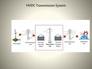
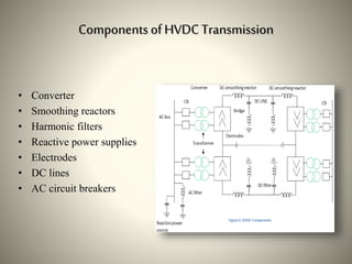
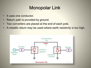
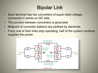
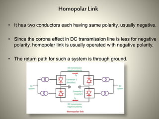
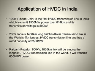


The document summarizes HVDC (High Voltage Direct Current) transmission. It discusses why DC transmission is used over long distances, the key components of an HVDC system including converters and transmission lines, and different HVDC system configurations like monopolar, bipolar, and homopolar links. It also provides examples of HVDC applications in India and notes that while HVDC transmission has high costs, it offers benefits like reduced losses over long distances and increased power transmission stability and flexibility.