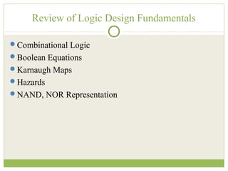
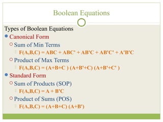
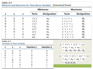
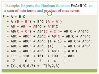
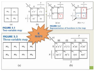
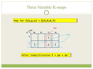
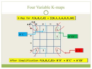
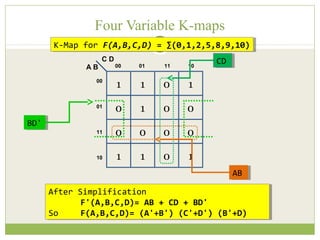
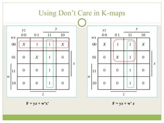
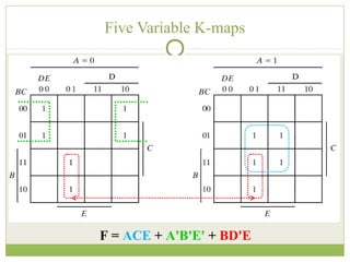
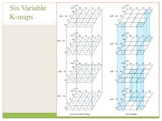
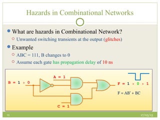
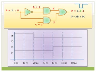
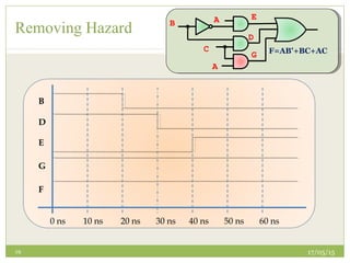
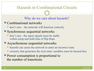
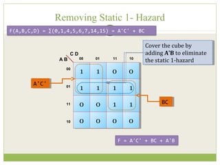
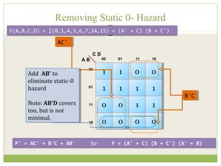
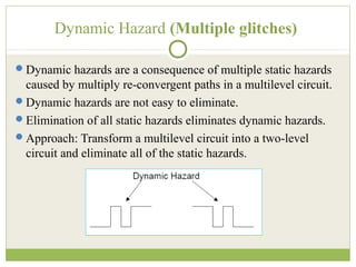
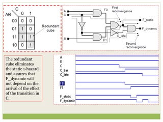
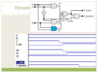
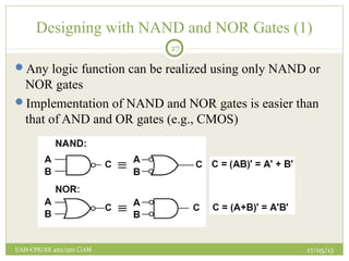
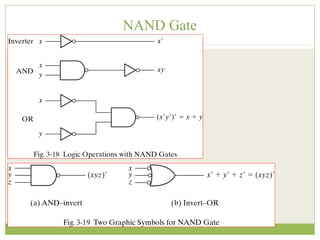
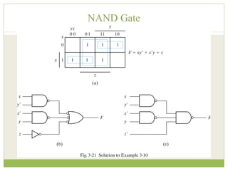
ENGR. RASHID FARID CHISHTI
LECTURER,DEE, FET, IIUI
CHISHTI@IIU.EDU.PK
WEEK 1
DIGITAL LOGIC DESIGN REVISION
FPGA Based System Design
Sunday, May 17, 2015
1
www.iiu.edu.pk
Review of Logic Design Fundamentals
Combinational Logic
Boolean Equations
Karnaugh Maps
Hazards
NAND, NOR Representation
Combinational Logic
3
Has no memory
 Output depends only on the present input
x1
x2
xn
z1
z2
zm
Note:
Positive Logic – low voltage corresponds to a logic 0, high voltage to a logic 1
Negative Logic – low voltage corresponds to a logic 1, high voltage to a logic 0
Combinational
Logic
Types of Boolean Equations
Canonical Form
 Sum of Min Terms
 F(A,B,C) = ABC + ABC' + AB'C + AB'C' + A'B'C
 Product of Max Terms
 F(A,B,C) = (A+B+C ) (A+B'+C) (A+B'+C' )
Standard Form
 Sum of Products (SOP)
 F(A,B,C) = A + B'C
 Product of Sums (POS)
 F(A,B,C) = (A+B+C) (A+B')
Boolean Equations
Min Max Terms
(Canonical Form)
F = A + B'C
= A (B + B') + B'C (A + A')
= AB + AB' + AB'C + A'B'C
= AB(C + C') + AB'(C + C')+ AB'C + A'B'C
= ABC + ABC' + AB'C + AB'C'+ AB'C + A'B'C
= ABC + ABC' + AB'C (1 + 1) + AB'C'+ A'B'C
= ABC + ABC' + AB'C (1) + AB'C'+ A'B'C
= ABC + ABC' + AB'C + AB'C' + A'B'C
= 111 + 110 + 101 + 100 + 001
= 7 + 6 + 5 + 4 + 1
= ∑(1,4,5,6,7) = ∏(0,2,3)
Example: Express the Boolean function F=A+B'C as
a sum of min terms and product of max terms
Convenient way to simplify logic functions of 2,3, 4, 5, (6)
variables
In a Four-variable K-map
 each square corresponds to one
of the 16 possible minterms
 1 = minterm is present;
 0 (or blank) = minterm is absent;
 X = don’t care
 the input can never occur, or
 the input occurs but the output is not specified
 adjacent cells differ in only one value =>
can be combined
K-maps
Location
of minterms
K-maps
Three Variable K-maps
1
1
1 1
00 01 11 10
0
1
x
y z
y z
After Simplification F = yz + xz'After Simplification F = yz + xz'
Map for F(x,y,z) = ∑(3,4,6,7)Map for F(x,y,z) = ∑(3,4,6,7)
x z '
Four Variable K-maps
K-Map for F(A,B,C,D) = ∑(0,1,2,6,8,9,10)K-Map for F(A,B,C,D) = ∑(0,1,2,6,8,9,10)
A B
1 1 1
1
00 01 11 10
00
01
11
10
C D
1 1 1
After Simplification F(A,B,C,D)= B'D' + B'C' + A'CD'After Simplification F(A,B,C,D)= B'D' + B'C' + A'CD'
A'CD'A'CD'
B'C'B'C'
B'D'B'D'
Four Variable K-maps
K-Map for F(A,B,C,D) = ∑(0,1,2,5,8,9,10)K-Map for F(A,B,C,D) = ∑(0,1,2,5,8,9,10)
A B
1 1
0 1
0 1
0 0
00 01 11 10
00
01
11
10
C D
0 0
1 1
0 0
0 1
After Simplification
F'(A,B,C,D)= AB + CD + BD'
So F(A,B,C,D)= (A'+B') (C'+D') (B'+D)
After Simplification
F'(A,B,C,D)= AB + CD + BD'
So F(A,B,C,D)= (A'+B') (C'+D') (B'+D)
CDCD
ABAB
BD'BD'
Using Don’t Care in K-maps
F = yz + w'x' F = yz + w' z
Five Variable K-maps
F = ACE + A'B'E' + BD'E
Six Variable
K-maps
17/05/1515
Hazards in Combinational Networks
What are hazards in Combinational Network?
 Unwanted switching transients at the output (glitches)
Example
 ABC = 111, B changes to 0
 Assume each gate has propagation delay of 10 ns
B = 1 › 0 F = 1 › 0 › 1
A = 1
C = 1
F = AB' + BC
0 ns 10 ns 20 ns 30 ns 40 ns 50 ns 60 ns
B
D
E
F
B = 1 › 0 F = 1›0›1
A = 1
C = 1
F = AB' + BC
E
D
17/05/1517
Hazards in Combinational Networks
Occur when different paths from input to output have
different propagation delays
Static 1-hazard
 a network output momentarily go to the 0 when it should remain a
constant 1
Static 0-hazard
 a network output momentarily go to the 1 when it should remain a
constant 0
Dynamic hazard
 if an output change three or more times, when the output is supposed
to change from 0 to 1 (1 to 0)
17/05/1518
Removing Hazard
BCABf += ' ACBCABf ++= '
To avoid hazards:
every pair of adjacent 1s should be covered by a 1-term
1
1
1 1
00 01 11 10
0
1
C
A B
1
1
1 1
00 01 11 10
0
1
C
A B
A
C
F = AB' + BC
D
E
B A
C F=AB'+BC+AC
D
E
B
A
G
17/05/15
UAH-
CPE/EE
422/522
AM
19
A
C F=AB'+BC+AC
E
D
B
A
G
0 ns 10 ns 20 ns 30 ns 40 ns 50 ns 60 ns
B
D
E
G
F
Removing Hazard
17/05/1520
Hazards in Combinational Circuits
Why do we care about hazards?
Combinational networks
 don’t care – the network will function correctly
Synchronous sequential networks
 don’t care - the input signals must be stable
within setup and hold time of flip-flops
Asynchronous sequential networks
 hazards can cause the network to enter an incorrect state
 circuitry that generates the next-state variables must be hazard-free
Power consumption is proportional to
the number of transitions
Removing Static 1- Hazard
F(A,B,C,D) = ∑(0,1,4,5,6,7,14,15) = A'C' + BC
A B
11 11
11 11
00 00
11 11
00 01 11 10
00
01
11
10
C D
00 00
00 00
11 11
00 00
A'C'A'C'
BCBC
Cover the cube by
adding A'B to eliminate
the static 1-hazard
Cover the cube by
adding A'B to eliminate
the static 1-hazard
F = A'C' + BC + A'B
In the logic diagram of
F = A'C' + BC
With a = 0, b = 1, and D = 1, a glitch can occur as c
changes from 1 to 0 or visa-versa.
So we add the redundant term A'B by overlapping the two
groups to eliminates the static 1-Hazard
Removing Static 1- Hazard
Removing Static 0- Hazard
F(A,B,C,D) = ∑(0,1,4,5,6,7,14,15) = (A' + C) (B + C')
A B
11 11
11 11
00 00
11 11
00 01 11 10
00
01
11
10
C D
00 00
00 00
11 11
00 00
AC'AC'
Add AB' to
eliminate static-0
hazard
Note: AB'D covers
too, but is not
minimal.
Add AB' to
eliminate static-0
hazard
Note: AB'D covers
too, but is not
minimal.
F' = AC' + B'C + AB' So F = (A' + C) (B + C') (A' + B)
B'CB'C
Dynamic hazards are a consequence of multiple static hazards
caused by multiply re-convergent paths in a multilevel circuit.
Dynamic hazards are not easy to eliminate.
Elimination of all static hazards eliminates dynamic hazards.
Approach: Transform a multilevel circuit into a two-level
circuit and eliminate all of the static hazards.
Dynamic Hazard (Multiple glitches)
The redundant
cube eliminates
the static 1-hazard
and assures that
F_dynamic will
not depend on the
arrival of the effect
of the transition in
C.
Dynamic Hazard (Multiple glitches)
Designing with NAND and NOR Gates (1)
17/05/15UAH-CPE/EE 422/522 AM
27
Any logic function can be realized using only NAND or
NOR gates
Implementation of NAND and NOR gates is easier than
that of AND and OR gates (e.g., CMOS)
NAND Gate
28
NAND Gate
29
NAND Gate
30
NAND Gate
31
Fpga 01-digital-logic-design

Fpga 01-digital-logic-design

  • 1.
    ENGR. RASHID FARIDCHISHTI LECTURER,DEE, FET, IIUI CHISHTI@IIU.EDU.PK WEEK 1 DIGITAL LOGIC DESIGN REVISION FPGA Based System Design Sunday, May 17, 2015 1 www.iiu.edu.pk
  • 2.
    Review of LogicDesign Fundamentals Combinational Logic Boolean Equations Karnaugh Maps Hazards NAND, NOR Representation
  • 3.
    Combinational Logic 3 Has nomemory  Output depends only on the present input x1 x2 xn z1 z2 zm Note: Positive Logic – low voltage corresponds to a logic 0, high voltage to a logic 1 Negative Logic – low voltage corresponds to a logic 1, high voltage to a logic 0 Combinational Logic
  • 4.
    Types of BooleanEquations Canonical Form  Sum of Min Terms  F(A,B,C) = ABC + ABC' + AB'C + AB'C' + A'B'C  Product of Max Terms  F(A,B,C) = (A+B+C ) (A+B'+C) (A+B'+C' ) Standard Form  Sum of Products (SOP)  F(A,B,C) = A + B'C  Product of Sums (POS)  F(A,B,C) = (A+B+C) (A+B') Boolean Equations
  • 5.
  • 6.
    F = A+ B'C = A (B + B') + B'C (A + A') = AB + AB' + AB'C + A'B'C = AB(C + C') + AB'(C + C')+ AB'C + A'B'C = ABC + ABC' + AB'C + AB'C'+ AB'C + A'B'C = ABC + ABC' + AB'C (1 + 1) + AB'C'+ A'B'C = ABC + ABC' + AB'C (1) + AB'C'+ A'B'C = ABC + ABC' + AB'C + AB'C' + A'B'C = 111 + 110 + 101 + 100 + 001 = 7 + 6 + 5 + 4 + 1 = ∑(1,4,5,6,7) = ∏(0,2,3) Example: Express the Boolean function F=A+B'C as a sum of min terms and product of max terms
  • 7.
    Convenient way tosimplify logic functions of 2,3, 4, 5, (6) variables In a Four-variable K-map  each square corresponds to one of the 16 possible minterms  1 = minterm is present;  0 (or blank) = minterm is absent;  X = don’t care  the input can never occur, or  the input occurs but the output is not specified  adjacent cells differ in only one value => can be combined K-maps Location of minterms
  • 8.
  • 9.
    Three Variable K-maps 1 1 11 00 01 11 10 0 1 x y z y z After Simplification F = yz + xz'After Simplification F = yz + xz' Map for F(x,y,z) = ∑(3,4,6,7)Map for F(x,y,z) = ∑(3,4,6,7) x z '
  • 10.
    Four Variable K-maps K-Mapfor F(A,B,C,D) = ∑(0,1,2,6,8,9,10)K-Map for F(A,B,C,D) = ∑(0,1,2,6,8,9,10) A B 1 1 1 1 00 01 11 10 00 01 11 10 C D 1 1 1 After Simplification F(A,B,C,D)= B'D' + B'C' + A'CD'After Simplification F(A,B,C,D)= B'D' + B'C' + A'CD' A'CD'A'CD' B'C'B'C' B'D'B'D'
  • 11.
    Four Variable K-maps K-Mapfor F(A,B,C,D) = ∑(0,1,2,5,8,9,10)K-Map for F(A,B,C,D) = ∑(0,1,2,5,8,9,10) A B 1 1 0 1 0 1 0 0 00 01 11 10 00 01 11 10 C D 0 0 1 1 0 0 0 1 After Simplification F'(A,B,C,D)= AB + CD + BD' So F(A,B,C,D)= (A'+B') (C'+D') (B'+D) After Simplification F'(A,B,C,D)= AB + CD + BD' So F(A,B,C,D)= (A'+B') (C'+D') (B'+D) CDCD ABAB BD'BD'
  • 12.
    Using Don’t Carein K-maps F = yz + w'x' F = yz + w' z
  • 13.
    Five Variable K-maps F= ACE + A'B'E' + BD'E
  • 14.
  • 15.
    17/05/1515 Hazards in CombinationalNetworks What are hazards in Combinational Network?  Unwanted switching transients at the output (glitches) Example  ABC = 111, B changes to 0  Assume each gate has propagation delay of 10 ns B = 1 › 0 F = 1 › 0 › 1 A = 1 C = 1 F = AB' + BC
  • 16.
    0 ns 10ns 20 ns 30 ns 40 ns 50 ns 60 ns B D E F B = 1 › 0 F = 1›0›1 A = 1 C = 1 F = AB' + BC E D
  • 17.
    17/05/1517 Hazards in CombinationalNetworks Occur when different paths from input to output have different propagation delays Static 1-hazard  a network output momentarily go to the 0 when it should remain a constant 1 Static 0-hazard  a network output momentarily go to the 1 when it should remain a constant 0 Dynamic hazard  if an output change three or more times, when the output is supposed to change from 0 to 1 (1 to 0)
  • 18.
    17/05/1518 Removing Hazard BCABf +=' ACBCABf ++= ' To avoid hazards: every pair of adjacent 1s should be covered by a 1-term 1 1 1 1 00 01 11 10 0 1 C A B 1 1 1 1 00 01 11 10 0 1 C A B A C F = AB' + BC D E B A C F=AB'+BC+AC D E B A G
  • 19.
    17/05/15 UAH- CPE/EE 422/522 AM 19 A C F=AB'+BC+AC E D B A G 0 ns10 ns 20 ns 30 ns 40 ns 50 ns 60 ns B D E G F Removing Hazard
  • 20.
    17/05/1520 Hazards in CombinationalCircuits Why do we care about hazards? Combinational networks  don’t care – the network will function correctly Synchronous sequential networks  don’t care - the input signals must be stable within setup and hold time of flip-flops Asynchronous sequential networks  hazards can cause the network to enter an incorrect state  circuitry that generates the next-state variables must be hazard-free Power consumption is proportional to the number of transitions
  • 21.
    Removing Static 1-Hazard F(A,B,C,D) = ∑(0,1,4,5,6,7,14,15) = A'C' + BC A B 11 11 11 11 00 00 11 11 00 01 11 10 00 01 11 10 C D 00 00 00 00 11 11 00 00 A'C'A'C' BCBC Cover the cube by adding A'B to eliminate the static 1-hazard Cover the cube by adding A'B to eliminate the static 1-hazard F = A'C' + BC + A'B
  • 22.
    In the logicdiagram of F = A'C' + BC With a = 0, b = 1, and D = 1, a glitch can occur as c changes from 1 to 0 or visa-versa. So we add the redundant term A'B by overlapping the two groups to eliminates the static 1-Hazard Removing Static 1- Hazard
  • 23.
    Removing Static 0-Hazard F(A,B,C,D) = ∑(0,1,4,5,6,7,14,15) = (A' + C) (B + C') A B 11 11 11 11 00 00 11 11 00 01 11 10 00 01 11 10 C D 00 00 00 00 11 11 00 00 AC'AC' Add AB' to eliminate static-0 hazard Note: AB'D covers too, but is not minimal. Add AB' to eliminate static-0 hazard Note: AB'D covers too, but is not minimal. F' = AC' + B'C + AB' So F = (A' + C) (B + C') (A' + B) B'CB'C
  • 24.
    Dynamic hazards area consequence of multiple static hazards caused by multiply re-convergent paths in a multilevel circuit. Dynamic hazards are not easy to eliminate. Elimination of all static hazards eliminates dynamic hazards. Approach: Transform a multilevel circuit into a two-level circuit and eliminate all of the static hazards. Dynamic Hazard (Multiple glitches)
  • 25.
    Dynamic Hazard (Multipleglitches) The redundant cube eliminates the static 1-hazard and assures that F_dynamic will not depend on the arrival of the effect of the transition in C.
  • 26.
  • 27.
    Designing with NANDand NOR Gates (1) 17/05/15UAH-CPE/EE 422/522 AM 27 Any logic function can be realized using only NAND or NOR gates Implementation of NAND and NOR gates is easier than that of AND and OR gates (e.g., CMOS)
  • 28.
  • 29.
  • 30.
  • 31.