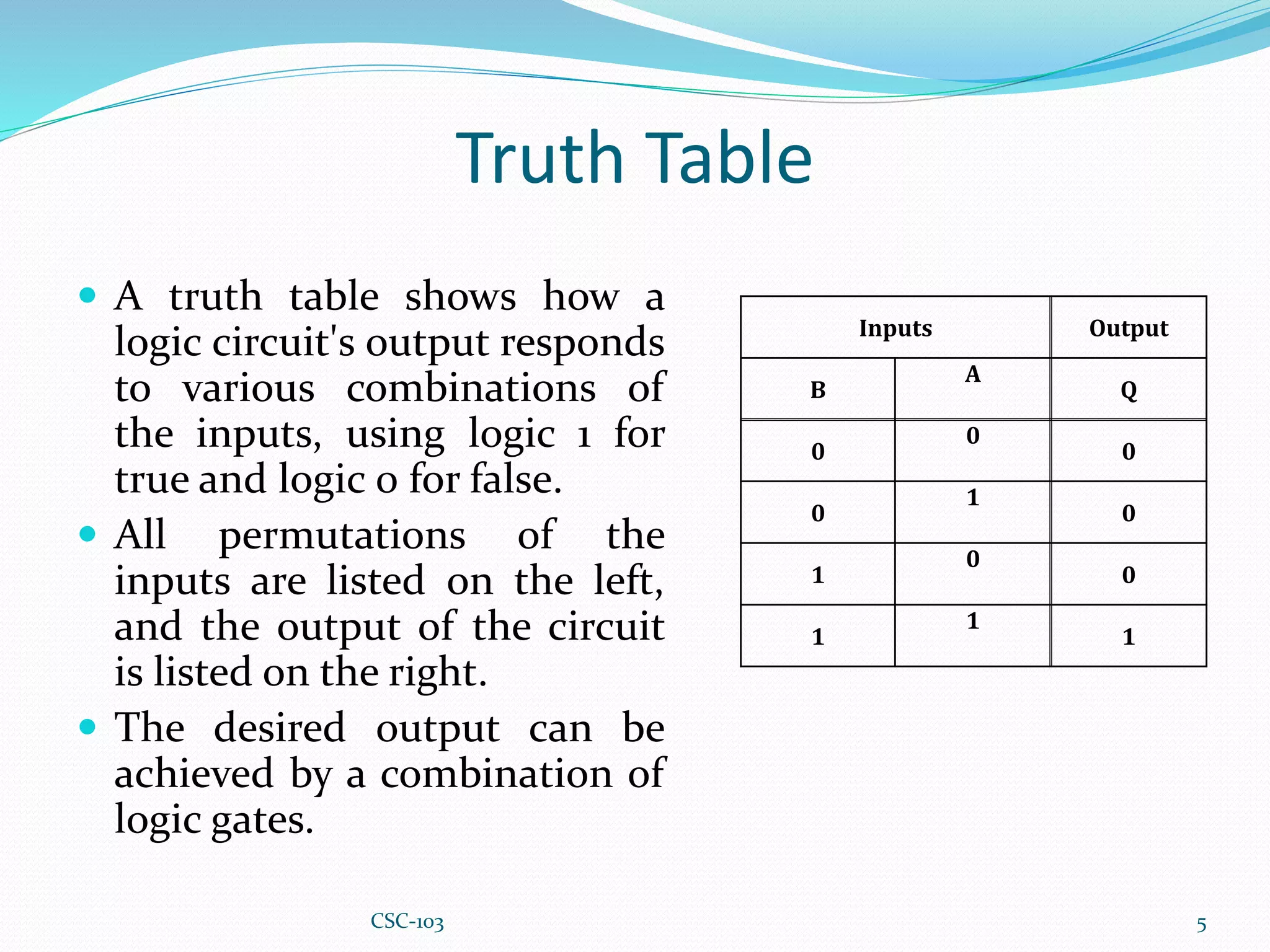
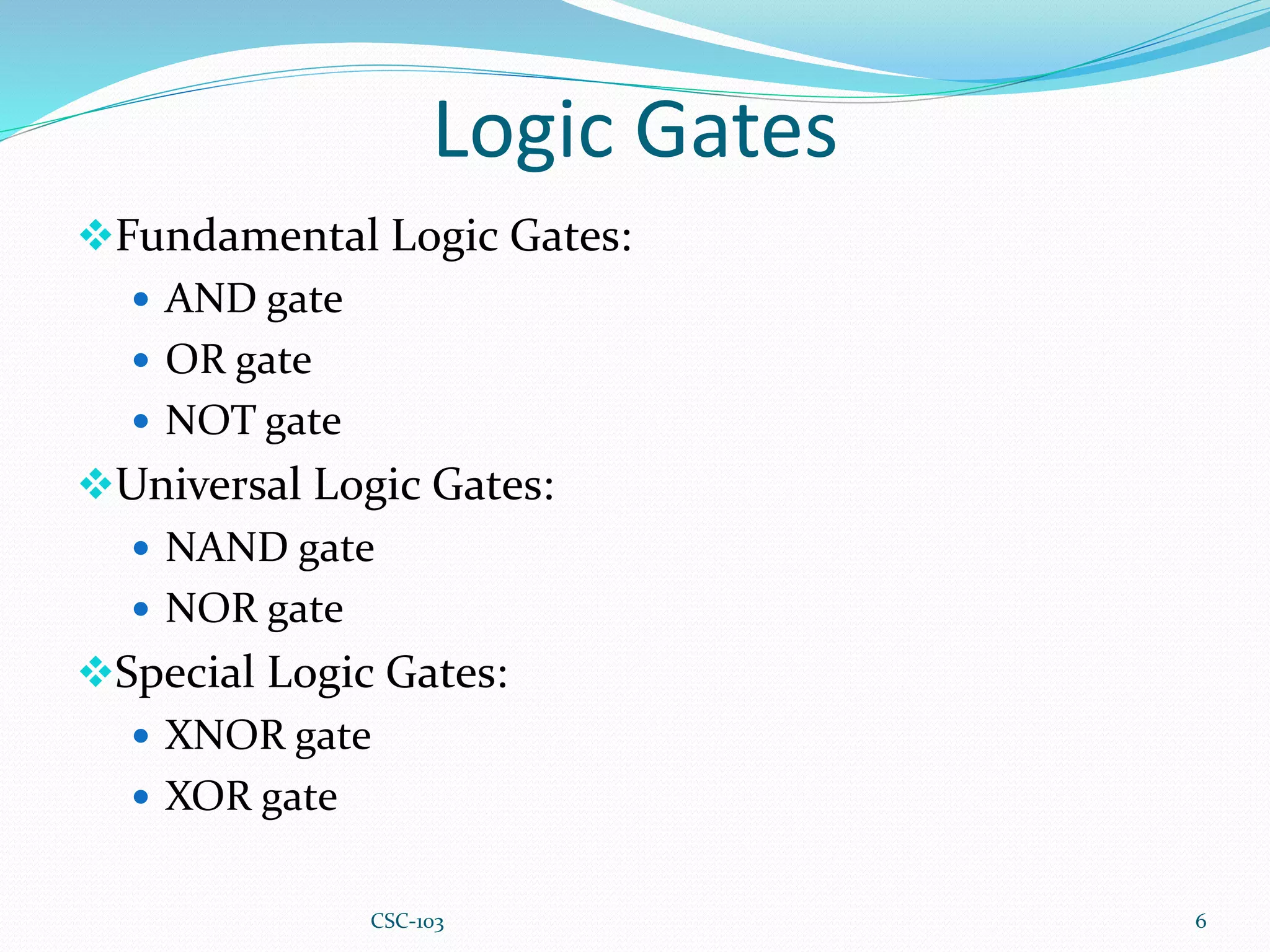
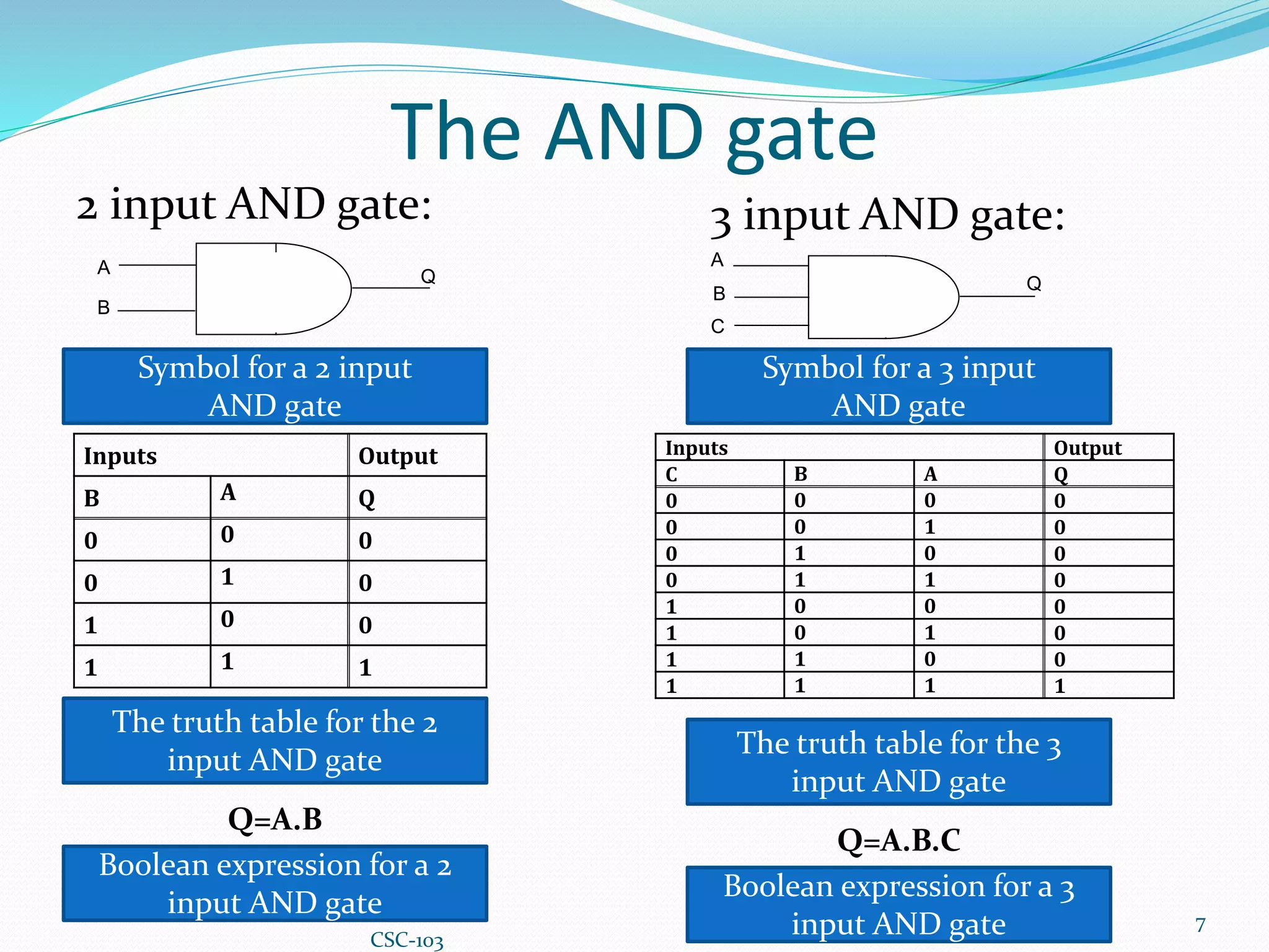
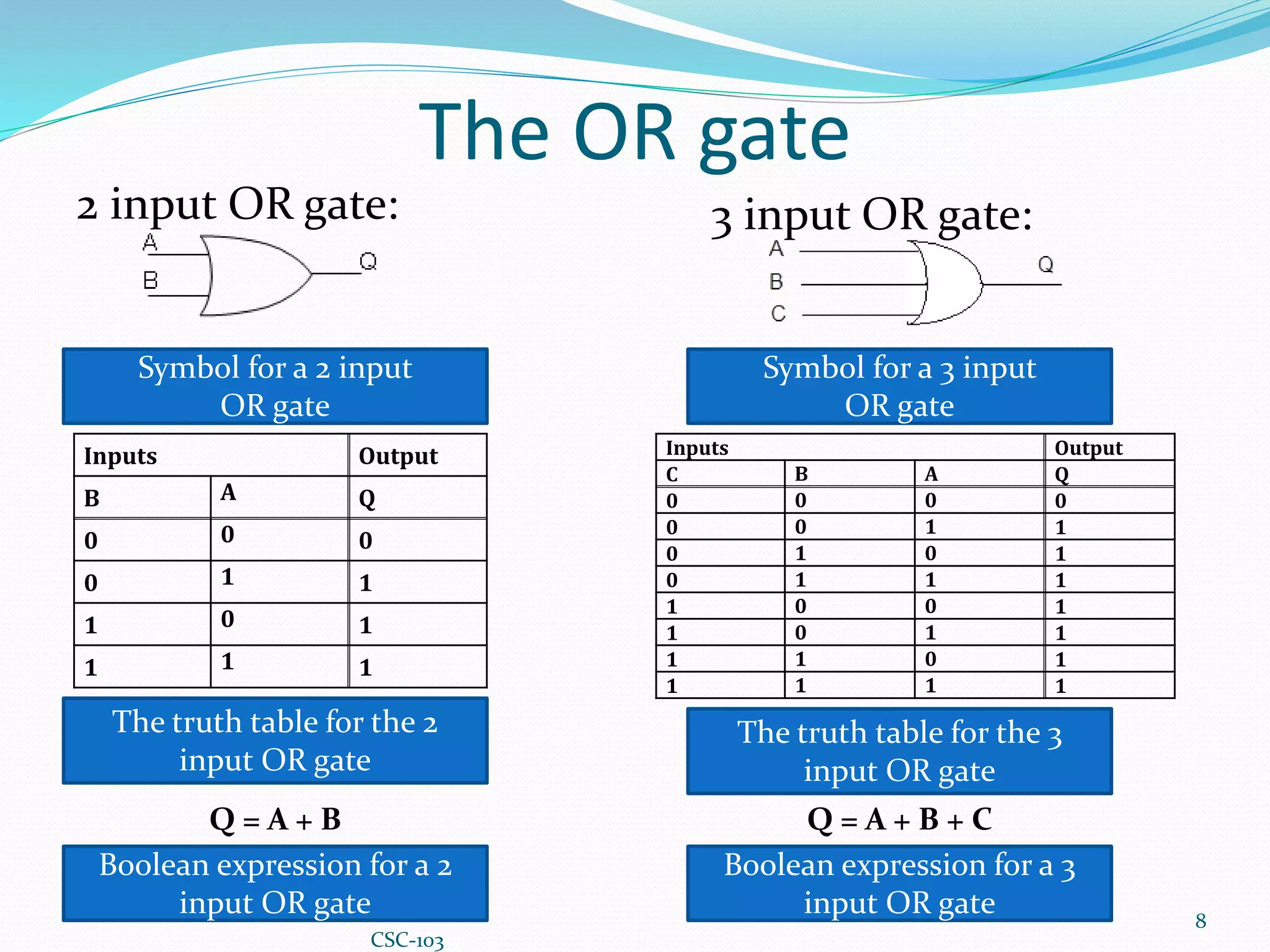
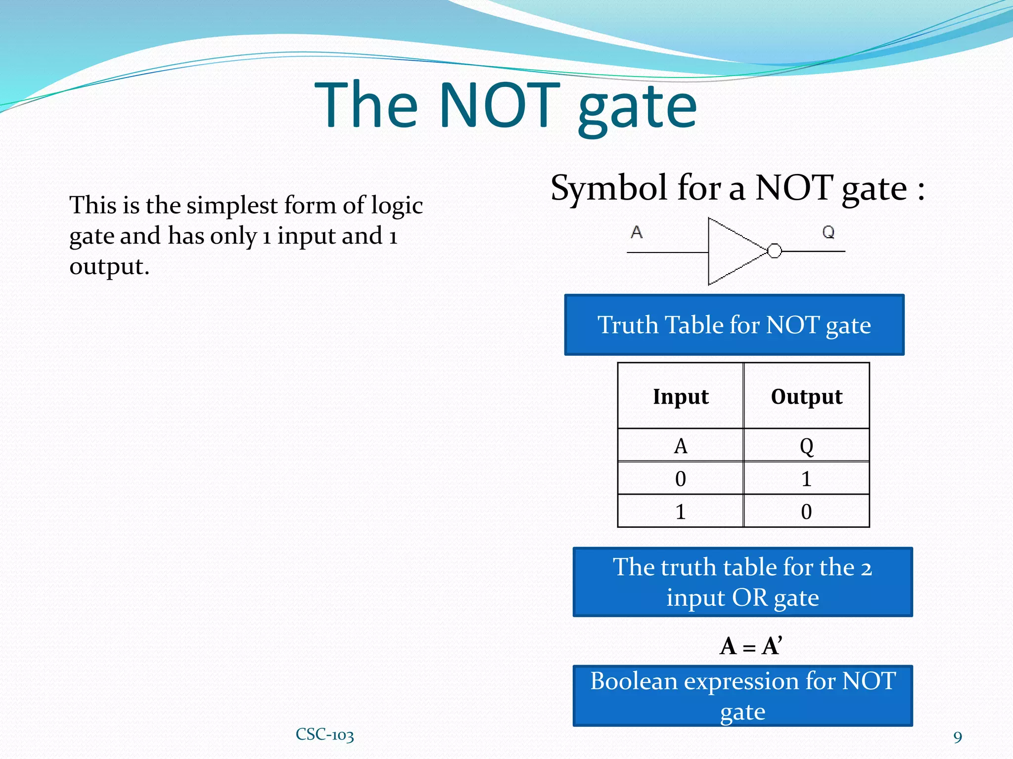
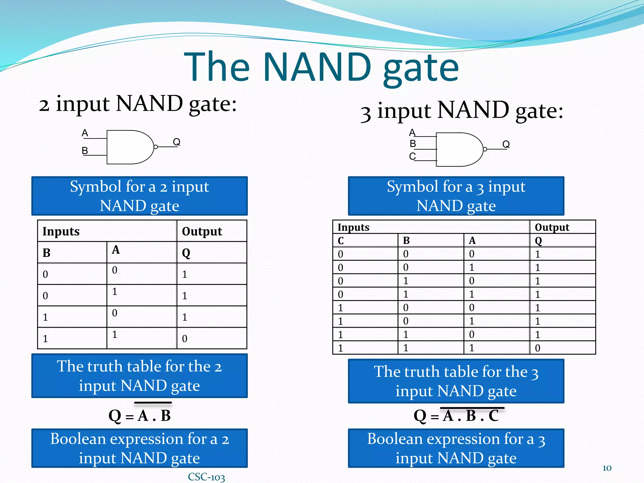
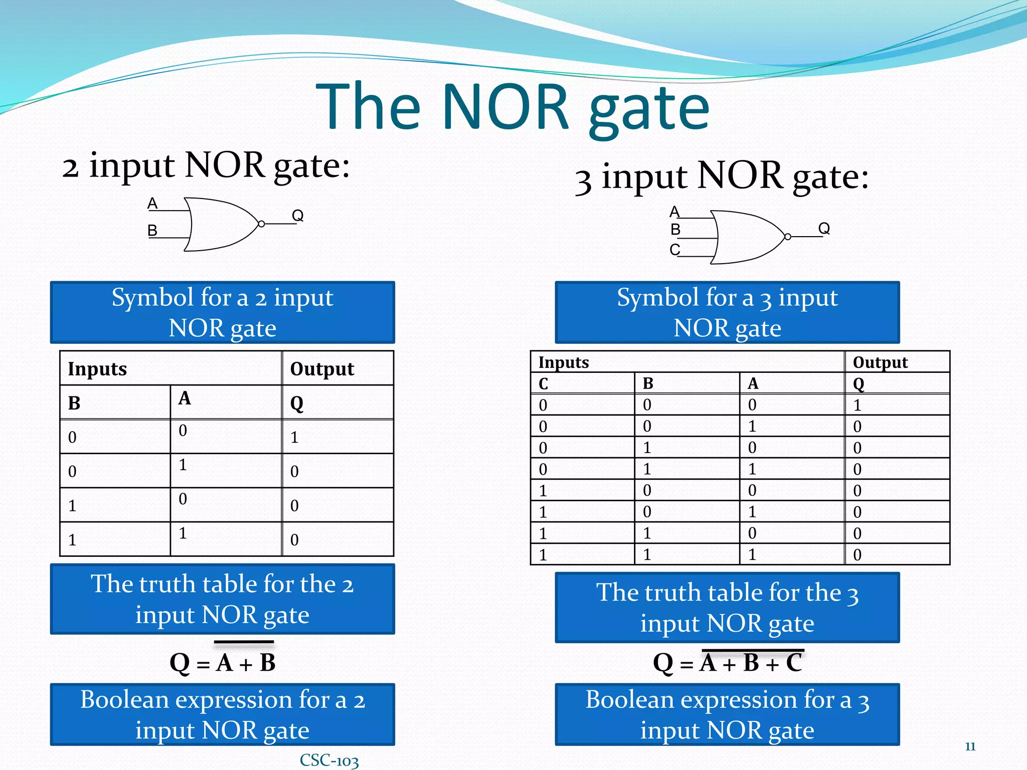
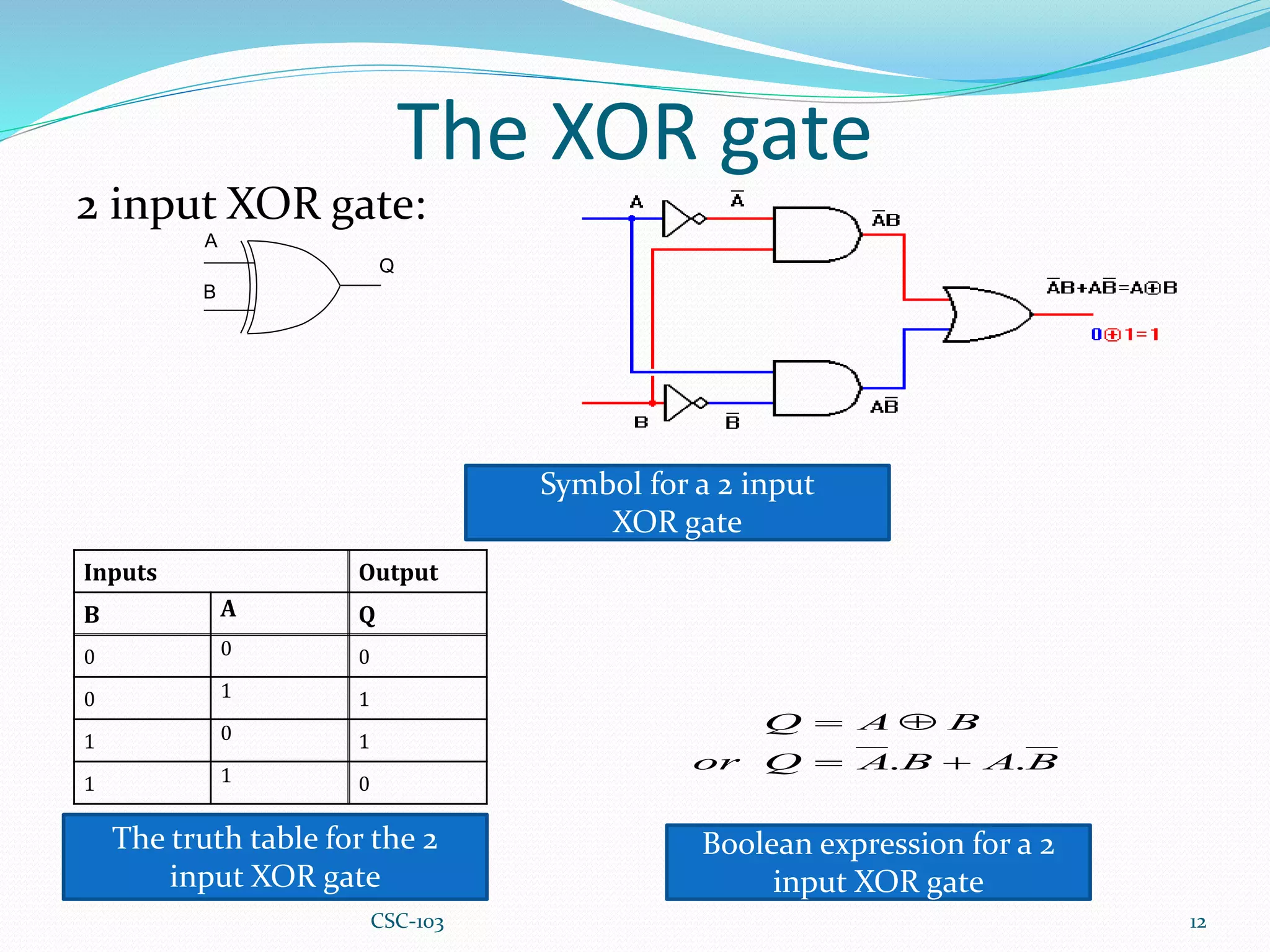
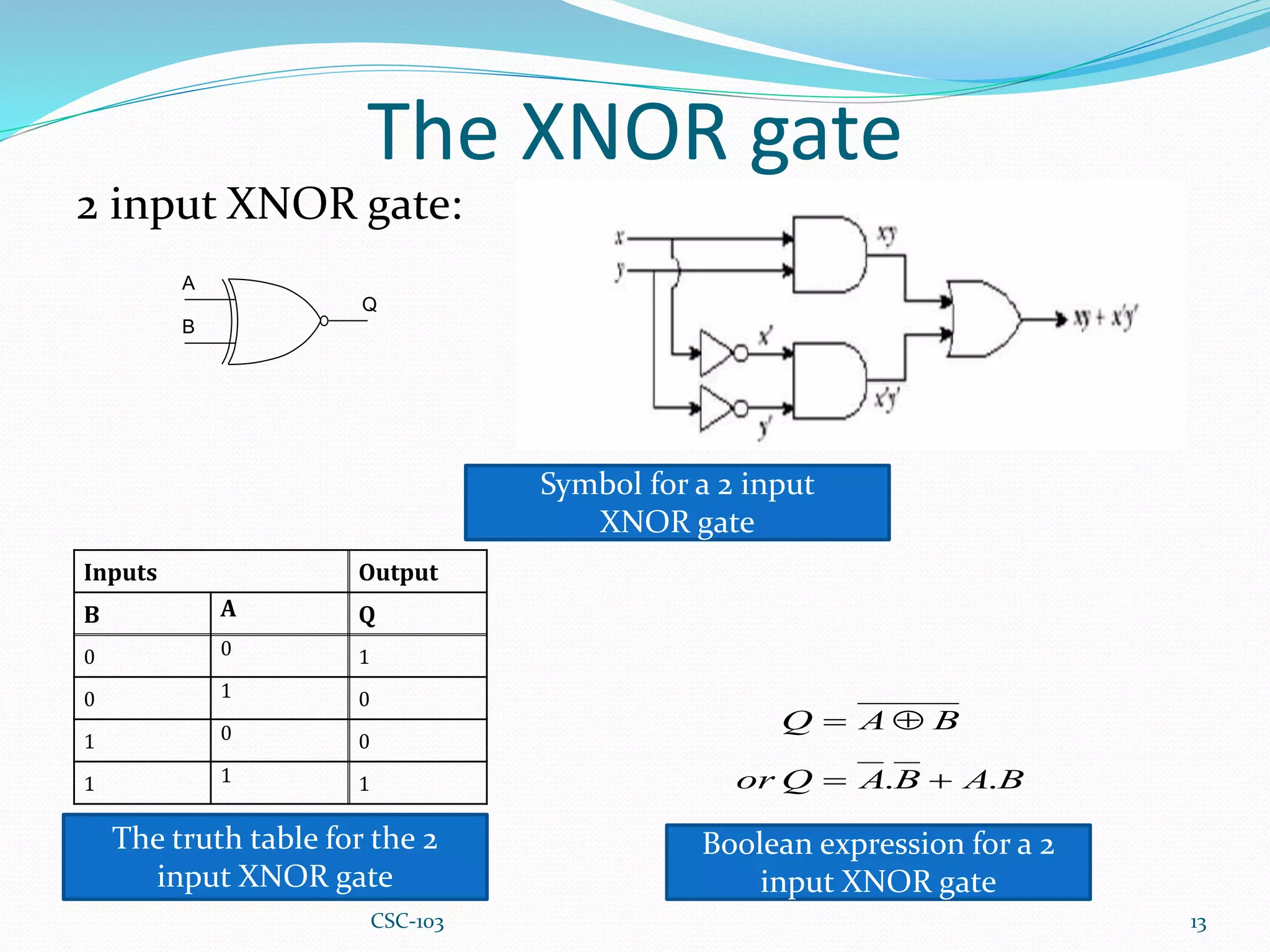
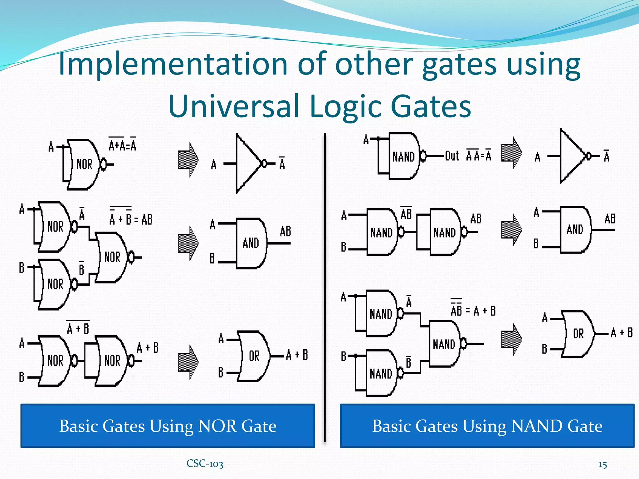
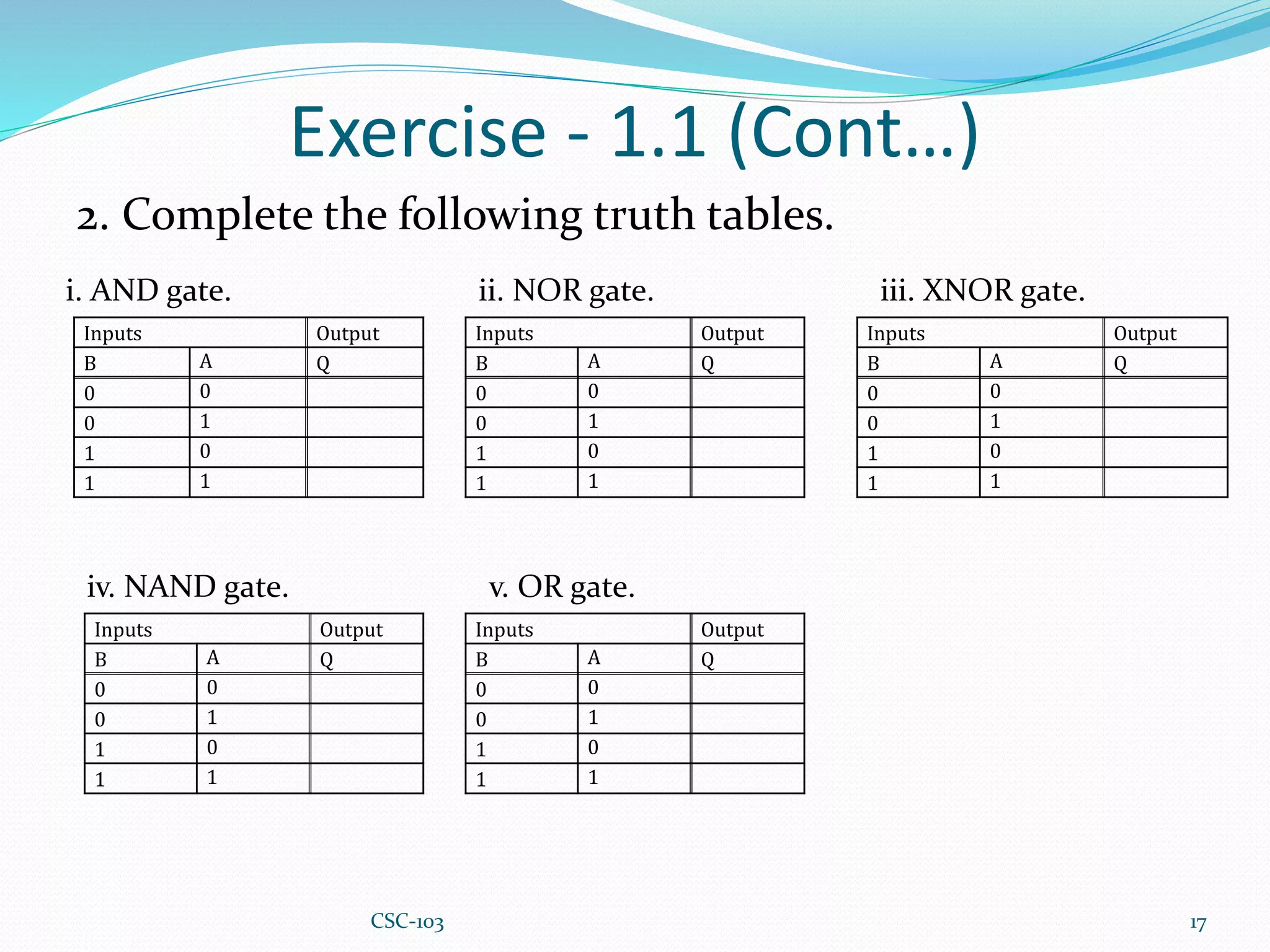
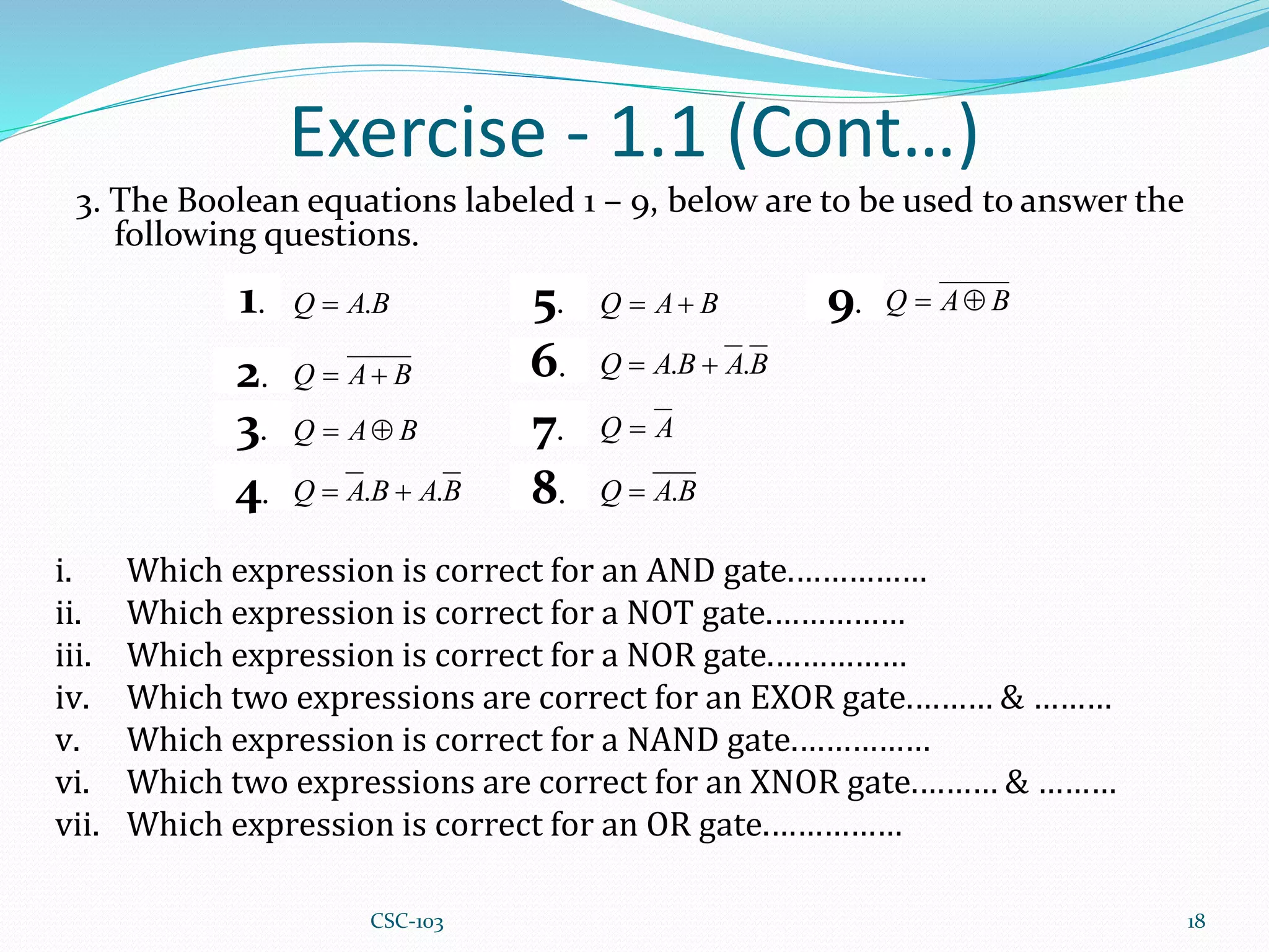
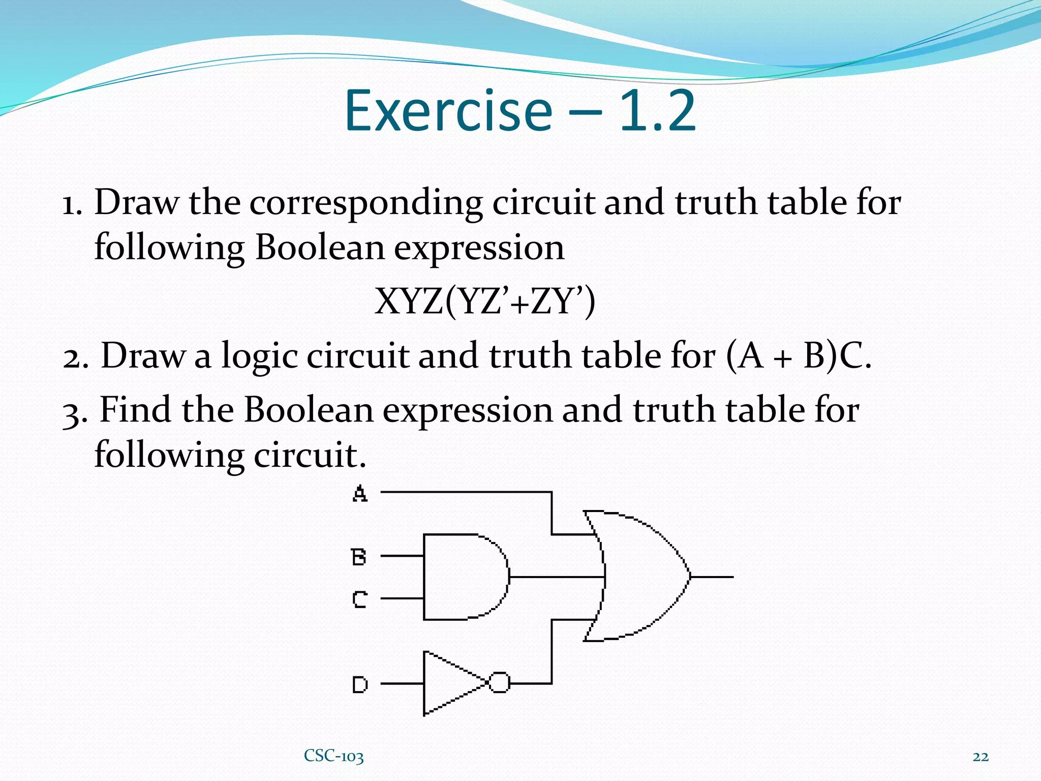
CSC-103 1
Outcome of this chapter
 Knowledge about logic gates, their expression, input
and output.
 Know how to draw circuits for Boolean expression.
 Know how to express a circuit through Boolean
expression.
2
CSC-103
Boolean Algebra
 Boolean algebra is the mathematics of Boolean logic,
where statements are evaluated to be either true or
false.
 It is extremely important in computer sciences, such
as programming, database querying and computer
engineering, as electrical signals at the most basic
level are translated to and from binary (true/false,
1/0, on/off, closed/open, etc).
3
CSC-103
Logic Gate
 A logic gate is an elementary building block of a digital
circuit.
 A Logic Gate in an electronic sense makes a ‘logical’
decision based upon a set of rules, and if the
appropriate conditions are met then the gate is
opened, and an output signal is produced.
 Most logic gates have two inputs and one output.
 At any given moment, every terminal is in one of the
two binary conditions low (0) or high (1), represented
by different voltage levels.
4
CSC-103
Truth Table
 A truth table shows how a
logic circuit's output responds
to various combinations of
the inputs, using logic 1 for
true and logic 0 for false.
 All permutations of the
inputs are listed on the left,
and the output of the circuit
is listed on the right.
 The desired output can be
achieved by a combination of
logic gates.
Inputs Output
B
A
Q
0
0
0
0
1
0
1
0
0
1
1
1
5
CSC-103
Logic Gates
Fundamental Logic Gates:
 AND gate
 OR gate
 NOT gate
Universal Logic Gates:
 NAND gate
 NOR gate
Special Logic Gates:
 XNOR gate
 XOR gate
6
CSC-103
The AND gate
2 input AND gate:
7
A
B
Q
Inputs Output
B A Q
0 0 0
0 1 0
1 0 0
1 1 1
The truth table for the 2
input AND gate
Symbol for a 2 input
AND gate
Q=A.B
Boolean expression for a 2
input AND gate
3 input AND gate:
A
B
Q
C
Inputs Output
C B A Q
0 0 0 0
0 0 1 0
0 1 0 0
0 1 1 0
1 0 0 0
1 0 1 0
1 1 0 0
1 1 1 1
Symbol for a 3 input
AND gate
The truth table for the 3
input AND gate
Q=A.B.C
Boolean expression for a 3
input AND gate
CSC-103
The OR gate
2 input OR gate:
8
Inputs Output
B A Q
0 0 0
0 1 1
1 0 1
1 1 1
The truth table for the 2
input OR gate
Symbol for a 2 input
OR gate
Q = A + B
Boolean expression for a 2
input OR gate
3 input OR gate:
Inputs Output
C B A Q
0 0 0 0
0 0 1 1
0 1 0 1
0 1 1 1
1 0 0 1
1 0 1 1
1 1 0 1
1 1 1 1
Symbol for a 3 input
OR gate
The truth table for the 3
input OR gate
Q = A + B + C
Boolean expression for a 3
input OR gate
CSC-103
The NOT gate
Symbol for a NOT gate :
9
The truth table for the 2
input OR gate
Truth Table for NOT gate
A = A’
Boolean expression for NOT
gate
Input Output
A Q
0 1
1 0
This is the simplest form of logic
gate and has only 1 input and 1
output.
CSC-103
The NAND gate
2 input NAND gate:
10
Inputs Output
B A Q
0 0 1
0 1 1
1 0 1
1 1 0
The truth table for the 2
input NAND gate
Symbol for a 2 input
NAND gate
Q = A . B
Boolean expression for a 2
input NAND gate
3 input NAND gate:
Inputs Output
C B A Q
0 0 0 1
0 0 1 1
0 1 0 1
0 1 1 1
1 0 0 1
1 0 1 1
1 1 0 1
1 1 1 0
Symbol for a 3 input
NAND gate
The truth table for the 3
input NAND gate
Q = A . B . C
Boolean expression for a 3
input NAND gate
A
B
Q Q
A
B
C
CSC-103
The NOR gate
2 input NOR gate:
11
Inputs Output
B A Q
0 0 1
0 1 0
1 0 0
1 1 0
The truth table for the 2
input NOR gate
Symbol for a 2 input
NOR gate
Q = A + B
Boolean expression for a 2
input NOR gate
3 input NOR gate:
Inputs Output
C B A Q
0 0 0 1
0 0 1 0
0 1 0 0
0 1 1 0
1 0 0 0
1 0 1 0
1 1 0 0
1 1 1 0
Symbol for a 3 input
NOR gate
The truth table for the 3
input NOR gate
Q = A + B + C
Boolean expression for a 3
input NOR gate
A
B
Q
Q
A
B
C
CSC-103
The XOR gate
2 input XOR gate:
12
Inputs Output
B A Q
0 0 0
0 1 1
1 0 1
1 1 0
The truth table for the 2
input XOR gate
Symbol for a 2 input
XOR gate
Boolean expression for a 2
input XOR gate
A
B
Q
B
A
B
A
Q
or
B
A
Q
.
. 



CSC-103
The XNOR gate
2 input XNOR gate:
13
Inputs Output
B A Q
0 0 1
0 1 0
1 0 0
1 1 1
The truth table for the 2
input XNOR gate
Symbol for a 2 input
XNOR gate
Boolean expression for a 2
input XNOR gate
A
B
Q
B
A
B
A
Q
or
B
A
Q
.
. 



CSC-103
Universal Logic Gates
 NAND and NOR gates are referred to as universal gates as
the three basic gates can be constructed using either one of
the two.
 This therefore implies that all logic circuits can be
constructed using either of the gates.
 NAND and NOR gates are economical and easier to
implement.
14
CSC-103
Implementation of other gates using
Universal Logic Gates
15
Basic Gates Using NOR Gate Basic Gates Using NAND Gate
CSC-103
Exercise - 1.1
1. Look at the following logic symbols labeled A – G.
16
i. Which is the correct symbol for an AND gate. ……………
ii. Which is the correct symbol for a NOT gate. ……………
iii.Which is the correct symbol for a NOR gate. ……………
iv.Which is the correct symbol for an EXOR gate. ……………
v. Which is the correct symbol for a NAND gate. ……………
vi.Which is the correct symbol for an XNOR gate. ……………
vii.Which is the correct symbol for an OR gate. ……………
CSC-103
Exercise - 1.1 (Cont…)
2. Complete the following truth tables.
17
i. AND gate.
Inputs Output
B A Q
0 0
0 1
1 0
1 1
ii. NOR gate.
Inputs Output
B A Q
0 0
0 1
1 0
1 1
iii. XNOR gate.
Inputs Output
B A Q
0 0
0 1
1 0
1 1
iv. NAND gate.
Inputs Output
B A Q
0 0
0 1
1 0
1 1
v. OR gate.
Inputs Output
B A Q
0 0
0 1
1 0
1 1
CSC-103
Exercise - 1.1 (Cont…)
3. The Boolean equations labeled 1 – 9, below are to be used to answer the
following questions.
18
B
A
Q .

B
A
Q 

B
A
Q 

B
A
B
A
Q .
. 

B
A
Q 

B
A
B
A
Q .
. 

A
Q 
B
A
Q .

B
A
Q 

1.
2.
3.
4.
5.
6.
7.
8.
9.
i. Which expression is correct for an AND gate.……………
ii. Which expression is correct for a NOT gate.……………
iii. Which expression is correct for a NOR gate.……………
iv. Which two expressions are correct for an EXOR gate.……… & ………
v. Which expression is correct for a NAND gate.……………
vi. Which two expressions are correct for an XNOR gate.……… & ………
vii. Which expression is correct for an OR gate.……………
CSC-103
Equation to Circuit
To convert a Boolean expression to a gate circuit, evaluate
the expression using standard order of operations:
1. To solve the equation start from the left to right
2. Parentheses
3. Inverse (Not Gate)
4. Multiplication (AND Gate)
5. Addition (OR Gate)
19
CSC-103
Circuit to Equation
To convert a gate circuit to a Boolean expression, label each
gate output with a Boolean sub-expression corresponding
to the gates' input signals, until a final expression is
reached at the last gate.
20
The Expression for above circuit is XʹY+XYʹ.
CSC-103
Class Practice
1. Draw the circuit diagram for the equation
i. AB + (AC)ʹ.
ii. (A+B) . (B+C)
iii. (A+B+C) . B . C
2. Write down the corresponding Boolean expression for
following circuit.
21
CSC-103
Exercise – 1.2
1. Draw the corresponding circuit and truth table for
following Boolean expression
XYZ(YZ’+ZY’)
2. Draw a logic circuit and truth table for (A + B)C.
3. Find the Boolean expression and truth table for
following circuit.
22
CSC-103
Thank You
23
CSC-103

Chapter 5 Basic Gates and Boolean Logic.pptx

  • 1.
  • 2.
    Outcome of thischapter  Knowledge about logic gates, their expression, input and output.  Know how to draw circuits for Boolean expression.  Know how to express a circuit through Boolean expression. 2 CSC-103
  • 3.
    Boolean Algebra  Booleanalgebra is the mathematics of Boolean logic, where statements are evaluated to be either true or false.  It is extremely important in computer sciences, such as programming, database querying and computer engineering, as electrical signals at the most basic level are translated to and from binary (true/false, 1/0, on/off, closed/open, etc). 3 CSC-103
  • 4.
    Logic Gate  Alogic gate is an elementary building block of a digital circuit.  A Logic Gate in an electronic sense makes a ‘logical’ decision based upon a set of rules, and if the appropriate conditions are met then the gate is opened, and an output signal is produced.  Most logic gates have two inputs and one output.  At any given moment, every terminal is in one of the two binary conditions low (0) or high (1), represented by different voltage levels. 4 CSC-103
  • 5.
    Truth Table  Atruth table shows how a logic circuit's output responds to various combinations of the inputs, using logic 1 for true and logic 0 for false.  All permutations of the inputs are listed on the left, and the output of the circuit is listed on the right.  The desired output can be achieved by a combination of logic gates. Inputs Output B A Q 0 0 0 0 1 0 1 0 0 1 1 1 5 CSC-103
  • 6.
    Logic Gates Fundamental LogicGates:  AND gate  OR gate  NOT gate Universal Logic Gates:  NAND gate  NOR gate Special Logic Gates:  XNOR gate  XOR gate 6 CSC-103
  • 7.
    The AND gate 2input AND gate: 7 A B Q Inputs Output B A Q 0 0 0 0 1 0 1 0 0 1 1 1 The truth table for the 2 input AND gate Symbol for a 2 input AND gate Q=A.B Boolean expression for a 2 input AND gate 3 input AND gate: A B Q C Inputs Output C B A Q 0 0 0 0 0 0 1 0 0 1 0 0 0 1 1 0 1 0 0 0 1 0 1 0 1 1 0 0 1 1 1 1 Symbol for a 3 input AND gate The truth table for the 3 input AND gate Q=A.B.C Boolean expression for a 3 input AND gate CSC-103
  • 8.
    The OR gate 2input OR gate: 8 Inputs Output B A Q 0 0 0 0 1 1 1 0 1 1 1 1 The truth table for the 2 input OR gate Symbol for a 2 input OR gate Q = A + B Boolean expression for a 2 input OR gate 3 input OR gate: Inputs Output C B A Q 0 0 0 0 0 0 1 1 0 1 0 1 0 1 1 1 1 0 0 1 1 0 1 1 1 1 0 1 1 1 1 1 Symbol for a 3 input OR gate The truth table for the 3 input OR gate Q = A + B + C Boolean expression for a 3 input OR gate CSC-103
  • 9.
    The NOT gate Symbolfor a NOT gate : 9 The truth table for the 2 input OR gate Truth Table for NOT gate A = A’ Boolean expression for NOT gate Input Output A Q 0 1 1 0 This is the simplest form of logic gate and has only 1 input and 1 output. CSC-103
  • 10.
    The NAND gate 2input NAND gate: 10 Inputs Output B A Q 0 0 1 0 1 1 1 0 1 1 1 0 The truth table for the 2 input NAND gate Symbol for a 2 input NAND gate Q = A . B Boolean expression for a 2 input NAND gate 3 input NAND gate: Inputs Output C B A Q 0 0 0 1 0 0 1 1 0 1 0 1 0 1 1 1 1 0 0 1 1 0 1 1 1 1 0 1 1 1 1 0 Symbol for a 3 input NAND gate The truth table for the 3 input NAND gate Q = A . B . C Boolean expression for a 3 input NAND gate A B Q Q A B C CSC-103
  • 11.
    The NOR gate 2input NOR gate: 11 Inputs Output B A Q 0 0 1 0 1 0 1 0 0 1 1 0 The truth table for the 2 input NOR gate Symbol for a 2 input NOR gate Q = A + B Boolean expression for a 2 input NOR gate 3 input NOR gate: Inputs Output C B A Q 0 0 0 1 0 0 1 0 0 1 0 0 0 1 1 0 1 0 0 0 1 0 1 0 1 1 0 0 1 1 1 0 Symbol for a 3 input NOR gate The truth table for the 3 input NOR gate Q = A + B + C Boolean expression for a 3 input NOR gate A B Q Q A B C CSC-103
  • 12.
    The XOR gate 2input XOR gate: 12 Inputs Output B A Q 0 0 0 0 1 1 1 0 1 1 1 0 The truth table for the 2 input XOR gate Symbol for a 2 input XOR gate Boolean expression for a 2 input XOR gate A B Q B A B A Q or B A Q . .     CSC-103
  • 13.
    The XNOR gate 2input XNOR gate: 13 Inputs Output B A Q 0 0 1 0 1 0 1 0 0 1 1 1 The truth table for the 2 input XNOR gate Symbol for a 2 input XNOR gate Boolean expression for a 2 input XNOR gate A B Q B A B A Q or B A Q . .     CSC-103
  • 14.
    Universal Logic Gates NAND and NOR gates are referred to as universal gates as the three basic gates can be constructed using either one of the two.  This therefore implies that all logic circuits can be constructed using either of the gates.  NAND and NOR gates are economical and easier to implement. 14 CSC-103
  • 15.
    Implementation of othergates using Universal Logic Gates 15 Basic Gates Using NOR Gate Basic Gates Using NAND Gate CSC-103
  • 16.
    Exercise - 1.1 1.Look at the following logic symbols labeled A – G. 16 i. Which is the correct symbol for an AND gate. …………… ii. Which is the correct symbol for a NOT gate. …………… iii.Which is the correct symbol for a NOR gate. …………… iv.Which is the correct symbol for an EXOR gate. …………… v. Which is the correct symbol for a NAND gate. …………… vi.Which is the correct symbol for an XNOR gate. …………… vii.Which is the correct symbol for an OR gate. …………… CSC-103
  • 17.
    Exercise - 1.1(Cont…) 2. Complete the following truth tables. 17 i. AND gate. Inputs Output B A Q 0 0 0 1 1 0 1 1 ii. NOR gate. Inputs Output B A Q 0 0 0 1 1 0 1 1 iii. XNOR gate. Inputs Output B A Q 0 0 0 1 1 0 1 1 iv. NAND gate. Inputs Output B A Q 0 0 0 1 1 0 1 1 v. OR gate. Inputs Output B A Q 0 0 0 1 1 0 1 1 CSC-103
  • 18.
    Exercise - 1.1(Cont…) 3. The Boolean equations labeled 1 – 9, below are to be used to answer the following questions. 18 B A Q .  B A Q   B A Q   B A B A Q . .   B A Q   B A B A Q . .   A Q  B A Q .  B A Q   1. 2. 3. 4. 5. 6. 7. 8. 9. i. Which expression is correct for an AND gate.…………… ii. Which expression is correct for a NOT gate.…………… iii. Which expression is correct for a NOR gate.…………… iv. Which two expressions are correct for an EXOR gate.……… & ……… v. Which expression is correct for a NAND gate.…………… vi. Which two expressions are correct for an XNOR gate.……… & ……… vii. Which expression is correct for an OR gate.…………… CSC-103
  • 19.
    Equation to Circuit Toconvert a Boolean expression to a gate circuit, evaluate the expression using standard order of operations: 1. To solve the equation start from the left to right 2. Parentheses 3. Inverse (Not Gate) 4. Multiplication (AND Gate) 5. Addition (OR Gate) 19 CSC-103
  • 20.
    Circuit to Equation Toconvert a gate circuit to a Boolean expression, label each gate output with a Boolean sub-expression corresponding to the gates' input signals, until a final expression is reached at the last gate. 20 The Expression for above circuit is XʹY+XYʹ. CSC-103
  • 21.
    Class Practice 1. Drawthe circuit diagram for the equation i. AB + (AC)ʹ. ii. (A+B) . (B+C) iii. (A+B+C) . B . C 2. Write down the corresponding Boolean expression for following circuit. 21 CSC-103
  • 22.
    Exercise – 1.2 1.Draw the corresponding circuit and truth table for following Boolean expression XYZ(YZ’+ZY’) 2. Draw a logic circuit and truth table for (A + B)C. 3. Find the Boolean expression and truth table for following circuit. 22 CSC-103
  • 23.