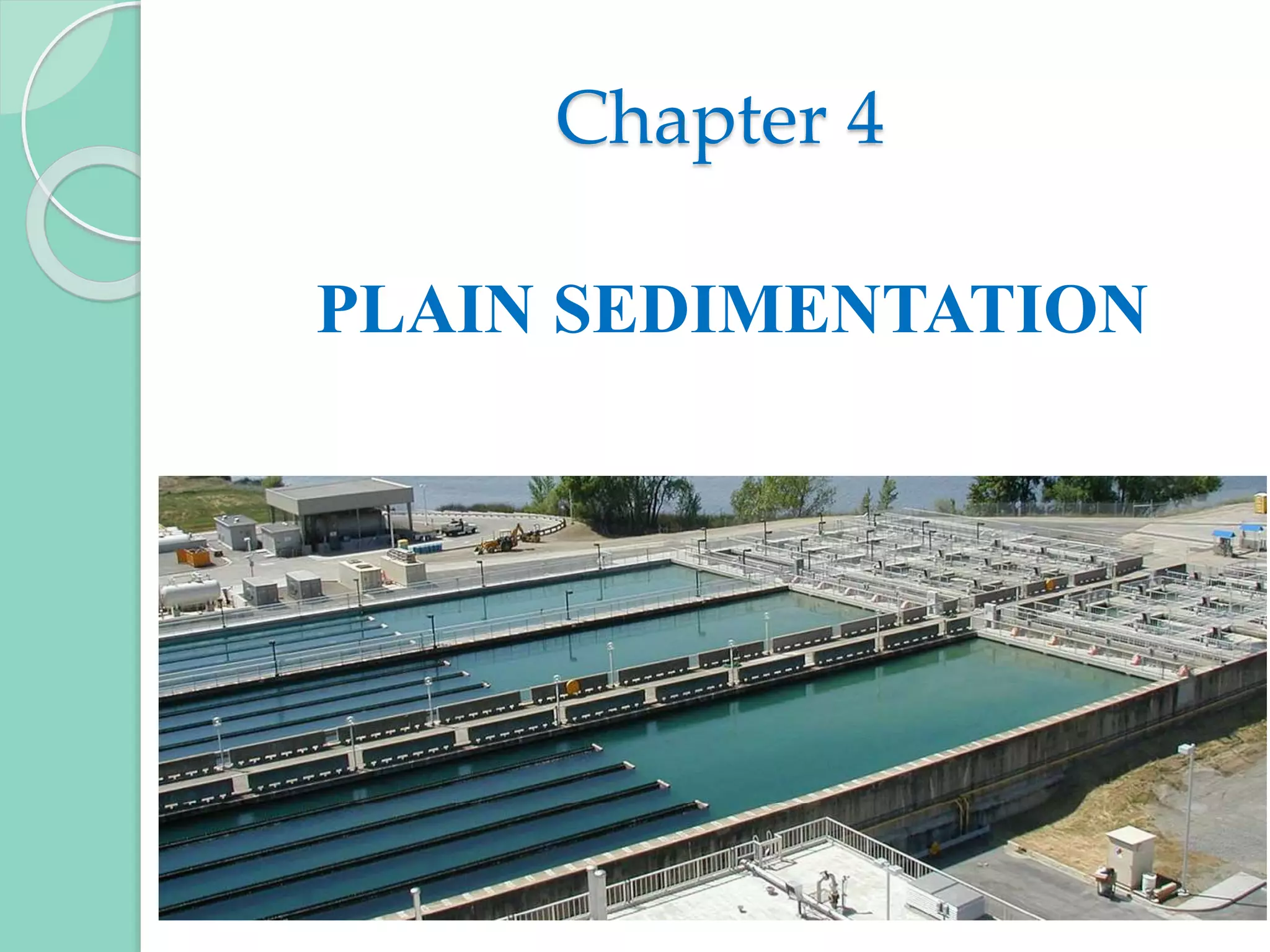
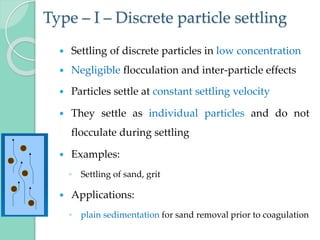
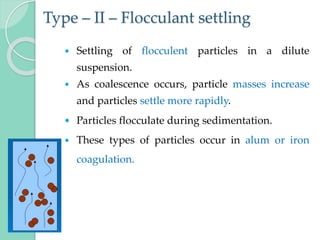
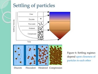
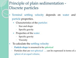
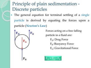
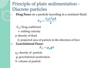
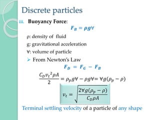
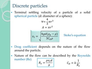
Chapter 4
PLAIN SEDIMENTATION
Sedimentation
 is a solid-liquid separation utilizing gravitational settling to
remove suspended solids.
 most of the suspended particles present in water have
specific gravity > 1.
 In still water, these particles will tend to settle down under
gravity.
1. Plain sedimentation
◦ when impurities are separated from water by the action
of gravity alone
◦ no chemicals are added to enhance the sedimentation
process
2. Coagulant aided sedimentation
◦ when the particles are too small to be removed by gravity
and aided with coagulants to increase size and
agglomeration.
Sedimentation
 Particle-fluid separation processes are difficult to
describe by theoretical analysis, mainly because the
particles involved are not regular in shape, density, or
size.
 The various regimes in settling of particles are
commonly referred to as:
Type – I: Discrete particle settling
Type – II: Flocculant settling
Type – III: Hindered (zone) settling
Type – IV: Compression settling
Type – I – Discrete particle settling
 Settling of discrete particles in low concentration
 Negligible flocculation and inter-particle effects
 Particles settle at constant settling velocity
 They settle as individual particles and do not
flocculate during settling
 Examples:
◦ Settling of sand, grit
 Applications:
◦ plain sedimentation for sand removal prior to coagulation
Type – II – Flocculant settling
 Settling of flocculent particles in a dilute
suspension.
 As coalescence occurs, particle masses increase
and particles settle more rapidly.
 Particles flocculate during sedimentation.
 These types of particles occur in alum or iron
coagulation.
Type – III – Hindered (zone) settling
◦ Settling in which particle concentration causes inter-
particle effects.
◦ Flocculation and rate of settling is a function of particle
concentration.
◦ Particles remain in a fixed position relative to each other,
and all settle at a constant velocity
◦ Mass of particles settle as a zone
◦ Zones of different particle concentrations (different
layers) may develop as a result of particles with different
settling velocities
◦ State of compression is reached at the bottom.
Type – IV – Compression settling
◦ Settling of particles that are of high concentration of
solids (sludge's)
◦ The particles touch each other and settling can occur
only by compression of the compacting mass.
◦ Occurs at lower depths of the sedimentation tanks
◦ Rate of compression is dependent on time and the
force caused by the weight of solids above the
compression layer.
Settling of particles
Figure 6: Settling regimes
depend upon closeness of
particles to each other
Discrete Flocculent Hindered Compression
Principle of plain sedimentation -
Discrete particles
 When particles settle discretely, the particle settling
velocity can be calculated and the basins can be
designed to remove a specific particle size.
STOKE’s LAW
 Particle falling in a fluid accelerates until the frictional
resistance, or drag on the particle is equal to the
gravitational force of the particle. Isaac NEWTON
 Settling velocity remains constant Terminal velocity
Principle of plain sedimentation -
Discrete particles
 Terminal settling velocity depends on water and
particle properties.
 Characteristics of the particles
◦ Size and shape
◦ Specific gravity
 Properties of the water
◦ Specific gravity
◦ Viscosity
 To calculate the settling velocity
◦ Particle shape is assumed to be spherical
◦ Particles that are not spherical … can be expressed in terms of a
sphere of an equal volume.
Principle of plain sedimentation -
Discrete particles
 The general equation for terminal settling of a single
particle is derived by equating the forces upon a
particle (Newton’s Law)
Forces acting on a free falling
particle in a fluid are:
FD: Drag Force
FB: Buoyancy Force
FG: Gravitational Force
FD = FG - FB
Principle of plain sedimentation -
Discrete particles
i. Drag Force on a particle traveling in a resistant fluid:
𝑭𝑫 =
𝑪𝑫𝒗𝟐𝝆𝑨
𝟐
CD: Drag coefficient
v: settling velocity
: density of fluid
A: projected area of particle in the direction of flow
ii. Gravitational Force:
𝑭𝑮 = 𝝆𝒑𝒈∀
p: density of particle
g: gravitational acceleration
∀: volume of particle
Discrete particles
iii. Buoyancy Force:
𝑭𝑩 = 𝝆𝒈∀
: density of fluid
g: gravitational acceleration
∀: volume of particle
 From Newton’s Law
𝑭𝑫 = 𝑭𝑮 − 𝑭𝑩
𝐶𝐷𝑣𝑡
2𝜌𝐴
2
= 𝜌𝑝𝑔∀ − 𝜌𝑔∀= ∀𝑔(𝜌𝑝 − 𝜌)
Terminal settling velocity of a particle of any shape
𝑣𝑡 =
2∀𝑔(𝜌𝑝 − 𝜌)
𝐶𝐷𝜌𝐴
Discrete particles
 Terminal settling velocity of a particle of a solid
spherical particle (d: diameter of a sphere):
∀=
4
3
𝜋𝑟3
𝐴 = 𝜋𝑟2
 Drag coefficient depends on the nature of the flow
around the particle.
 Nature of the flow can be described by the Reynolds
number (Re)
𝑣𝑡 =
4𝑔𝑑(𝜌𝑝 − 𝜌)
3𝐶𝐷𝜌
Stoke’s equation
𝑅𝑒 =
𝜌𝑣𝑡𝑑
𝜇
𝐶𝐷 = 𝑘
1
𝑅𝑒
Discrete particles
i. For Re less than 2, Laminar flow
Cd is related to Re by the linear expression as follows:
𝐶𝐷 =
24
𝑅𝑒
 For laminar flow conditions
ii. 2 < Re< 500 - 1000, Transition zone
𝐶𝑑 =
24
𝑅𝑒
+
3
𝑅𝑒
+ 0.34
 The value of vt is solved by iteration.
◦ first, assume the flow is laminar and calculate Cd,
◦ compute vt and Re and,
◦ with computed Re, compute Cd until the values of vt
converges.
𝑣𝑡 =
𝑔(𝜌𝑝 − 𝜌)𝑑2
18𝜇
Discrete particles
iii. 500 - 1000 < Re< 200,000, Turbulent flow zone
𝐶𝑑 = 0.44
 Terminal velocity becomes
𝑣𝑡 = 1.74
𝑔(𝜌𝑝 − 𝜌)𝑑
𝜌
Drag Coefficient on a Sphere
laminar
Re t
V d


turbulent
turbulent
boundary
0.1
1
10
100
1000
Drag
Coefficient
Reynolds Number
Stokes Law
24
Re
d
C 
 



18
2


p
t
g
d
V
Figure 7: Variation of drag coefficient Cd with Reynolds number Re
for single particle sedimentation
𝑣𝑡 =
4𝑔𝑑(𝜌𝑝 − 𝜌)
3𝐶𝐷𝜌
Discrete particles
 Example 1
Find the terminal settling velocity of a spherical particle
with diameter of 0.5mm and a specific gravity (sg) of
2.65 settling through water at 20°c ( = 1.002*10-3
Ns/m2, w = 1000kg/m3).
Ans: vt = 0.091m/sec
Design Aspects of Sedimentation Tanks
 Particle settling is dependent on the nature of the
particle and geometry of the sedimentation process.
 In practice, settling of the particles is governed by the
resultant of horizontal velocity of water and the vertical
downward velocity of the particle.
 Particles move horizontally with the fluid (all
particles have the same horizontal velocity)
 Particles move vertically with terminal settling
velocity (different for particles with different size, shape
and density)
 The path of the settling particle is as shown in Figure
below.
Design Aspects of Sedimentation Tanks
Figure: Horizontal and vertical velocity of settling of particles
Particle 2
Particle 1
Particle 3
Design Aspects of Sedimentation Tanks
 The critical particle in the settling zone of an ideal
rectangular sedimentation tank, for design purposes,
will be:
◦ particle that enters at the top of the settling zone and
settles with a velocity just sufficient to reach the sludge
zone at the outlet end of the tank.
 In an ideal sedimentation tank with horizontal or radial
flow pattern, particles with settling velocity less than vs
(vt) can still be removed partially.
Design Aspects of Sedimentation Tanks
 The design aspects of sedimentary tanks are:
i. Velocity of flow
ii. Capacity of tank
iii. Inlet and outlet arrangements
iv. Settling and sludge zones
v. Shapes of tanks
vi. Miscellaneous considerations
Design Aspects of Sedimentation Tanks
1. Velocity of flow:
◦ should be sufficient enough to cause the hydraulic settling
of suspended impurities
◦ should remain uniform throughout the tank
◦ is generally not allowed to exceed 0.15 to 0.3m/min
2. Capacity of tank:
◦ Capacity of tank is calculated by
i. Detention period
ii. Overflow rate
Design Aspects of Sedimentation Tanks
i. Detention period
◦ The theoretical time taken by a particle of water to
pass between entry and exit of a settling tank
◦ The capacity of tank is calculated by:
V = C = Q * T where C - Capacity of tank
Q - Discharge or rate of flow
T - Detention period in hours
◦ The detention period depends on the quality of
suspended impurities present in water.
◦ For plain sedimentation tanks, the detention period
is found to vary from 3 to 4 hours.
Design Aspects of Sedimentation Tanks
ii. Overflow Rate
 It is assumed that the settlement of a particle at the
bottom of the tank:
◦ does not depend on the depth of tank
◦ depends upon the surface area of the tank
 Settling time:
= 𝒕𝒔 =
𝑯
𝑽𝒔
 Detention time:
= 𝒕𝒅 =
𝑳
𝑽
 𝑉 =
𝑄
𝑊𝐻
horizontal velocity of water particle
Design Aspects of Sedimentation Tanks
ii. Overflow Rate
 To get the desired settling with most efficient tank
size, td = ts , which occurs when Vo = Vs = Vt.
Where, L → Length of tank
W → Width of tank
Ap → Plan area of tank
Q → Discharge or rate of flow
Vs → Velocity of descend of a particle to the bottom of tank
Vo → overflow rate / surface loading rate /critical velocity
V → horizontal velocity of particle
p
o
A
Q
LW
Q
HW
Q
L
H
L
HV
V 



Design Aspects of Sedimentation Tanks
3. Inlet and Outlet Arrangements
 Inlet zone
 Purposes:
◦ to distribute the water
◦ to control the water's velocity as it enters the basin
 The incoming flow in a sedimentation basin must be
evenly distributed across the width of the basin to
prevent short-circuiting (caused by wind effects, …)
◦ Short-circuiting is a problematic circumstance in which water
bypasses the normal flow path through the basin and reaches
the outlet in less than the normal detention time.
Design Aspects of Sedimentation Tanks
Figure 8: Horizontal and vertical velocity of settling of particles
Design Aspects of Sedimentation Tanks
3. Inlet and Outlet Arrangements
 Outlet Zone
 The outlet zone controls the water flowing out of the
sedimentation basin
◦ designed to prevent short-circuiting of water in the basin.
◦ to ensure that only well-settled water leaves the basin and
enters the filter.
◦ used to control the water level in the basin.
 Outlet arrangement consists of
(i) weir, notches or orifices
(ii) effluent trough or launder
(iii) outlet pipe
Design Aspects of Sedimentation Tanks
 Outlet Zone
◦ Weir loading rates are limited to prevent high
approach velocities near the outlet.
◦ Weirs frequently consist of V-notches approximately
50mm in depth, placed 150 – 300mm on centers, with
a baffle in front of the weir:
 to prevent floating material from escaping the sedimentation
basin and clogging the filters.
Design Aspects of Sedimentation Tanks
4. Settling and Sludge Zones
 Settling Zone
◦ Zone where particle settling occurs
◦ this zone will make up the largest volume of the
sedimentation basin.
◦ for optimal performance, the settling zone requires a
slow, even flow of water. (insignificant turbulence, laminar
flow)
◦ The settling zone may be simply a large expanse of
open water.
◦ But in some cases, tube settlers and lamella plates are
included in the settling zone.
Design Aspects of Sedimentation Tanks
 Tube settlers and lamella plates: (55° to 60° )
◦ increase the settling efficiency and speed in sedimentation
basins.
◦ functions as a miniature sedimentation basin, greatly
increasing the settling area.
◦ are very useful in plants where site area is limited, in
packaged plants, or to increase the capacity of shallow
basins.
Design Aspects of Sedimentation Tanks
4. Settling and Sludge Zones
 Sludge Zone
◦ Found across the bottom of the sedimentation basin where
the sludge collects temporarily.
◦ Velocity in this zone should be very slow to prevent re-
suspension of sludge.
◦ A drain at the bottom of the basin allows the sludge to be
easily removed from the tank.
◦ The tank bottom should slope toward the drains to further
facilitate sludge removal.
◦ Sludge removal:
 using automated equipment
 manually
Design Aspects of Sedimentation Tanks
5. Shapes of Tanks
i. Rectangular tanks with horizontal flow
ii. Circular tanks with radial or spiral flow
The detention time for a circular tank
t =
d2
(0.011d + 0.785H)
Q
Design Aspects of Sedimentation Tanks
 Parameters for satisfactory performance of
sedimentation tank.
1. Detention period ….. 3 to 4 hours for plain settling
2 to 2.5 hours for floc settling
1 to 1.5 hours for vertical flow type
2. Overflow rate ……… 15 - 30 m3/m2/day for plain settling
30 - 40m3/m2/day for horizontal flow
40 - 50m3/m2/day for vertical flow
3. Velocity of flow…….. 0.5 to 1.0 cm/sec
4. Weir loading………... 300m3/m/day
Design Aspects of Sedimentation Tanks
 Parameters for satisfactory performance of
sedimentation tank.
5. L:W …………………. 3:1 to 5:1
Width of tank…….. (10 to 12m) to 30 to 50m
6. Depth of tank…… 2.5 to 5m (with a preferred value of 3m)
7. Diameter of circular tank…. up to 60m
8. Turbidity of water after sedimentation ….. 15 to 20 NTU.
9. Inlet and Outlet zones………. 0.75 to 1.0m
10. Free board…………………… 0.5m
11. Sludge Zone…………………. 0.5m
Overview of design calculations
 Determine the surface area, dimensions, and volume of
the sedimentation tank as well as the weir length.
 The calculations are as follows:
1. Divide flow into at least two tanks.
2. Calculate the required surface area.
3. Calculate the required volume.
4. Calculate the tank depth.
5. Calculate the tank width and length.
6. Check flow velocity.
7. If velocity is too high, repeat calculations with more tanks.
8. Calculate the weir length.
Design Aspects of Sedimentation Tanks
Example 2:
A water treatment plant has four clarifiers treating 0.175 m3/s
of water. Each clarifier is 4.9m wide, 24.4m long and 4.6m
deep. Determine: (a) the detention time, (b) overflow rate, (c)
horizontal velocity, and (d) weir loading rate assuming the
weir length is 2.5 times the basin width.
Example 3:
Find the settling velocity (vs) for sand particles with a
diameter of 0.08mm. ρp= 2650 kg/m3, µ = 1.002*10‐3Ns/m2 at
20°C. Using the calculated settling velocity of the given sand
as overflow rate, design plain sedimentation tanks to be used
to remove sand from river water that is used to produce
20,000m3/d drinking water. Use two tanks.

Chapter 4.pptx

  • 1.
  • 2.
    Sedimentation  is asolid-liquid separation utilizing gravitational settling to remove suspended solids.  most of the suspended particles present in water have specific gravity > 1.  In still water, these particles will tend to settle down under gravity. 1. Plain sedimentation ◦ when impurities are separated from water by the action of gravity alone ◦ no chemicals are added to enhance the sedimentation process 2. Coagulant aided sedimentation ◦ when the particles are too small to be removed by gravity and aided with coagulants to increase size and agglomeration.
  • 3.
    Sedimentation  Particle-fluid separationprocesses are difficult to describe by theoretical analysis, mainly because the particles involved are not regular in shape, density, or size.  The various regimes in settling of particles are commonly referred to as: Type – I: Discrete particle settling Type – II: Flocculant settling Type – III: Hindered (zone) settling Type – IV: Compression settling
  • 4.
    Type – I– Discrete particle settling  Settling of discrete particles in low concentration  Negligible flocculation and inter-particle effects  Particles settle at constant settling velocity  They settle as individual particles and do not flocculate during settling  Examples: ◦ Settling of sand, grit  Applications: ◦ plain sedimentation for sand removal prior to coagulation
  • 5.
    Type – II– Flocculant settling  Settling of flocculent particles in a dilute suspension.  As coalescence occurs, particle masses increase and particles settle more rapidly.  Particles flocculate during sedimentation.  These types of particles occur in alum or iron coagulation.
  • 6.
    Type – III– Hindered (zone) settling ◦ Settling in which particle concentration causes inter- particle effects. ◦ Flocculation and rate of settling is a function of particle concentration. ◦ Particles remain in a fixed position relative to each other, and all settle at a constant velocity ◦ Mass of particles settle as a zone ◦ Zones of different particle concentrations (different layers) may develop as a result of particles with different settling velocities ◦ State of compression is reached at the bottom.
  • 7.
    Type – IV– Compression settling ◦ Settling of particles that are of high concentration of solids (sludge's) ◦ The particles touch each other and settling can occur only by compression of the compacting mass. ◦ Occurs at lower depths of the sedimentation tanks ◦ Rate of compression is dependent on time and the force caused by the weight of solids above the compression layer.
  • 8.
    Settling of particles Figure6: Settling regimes depend upon closeness of particles to each other Discrete Flocculent Hindered Compression
  • 9.
    Principle of plainsedimentation - Discrete particles  When particles settle discretely, the particle settling velocity can be calculated and the basins can be designed to remove a specific particle size. STOKE’s LAW  Particle falling in a fluid accelerates until the frictional resistance, or drag on the particle is equal to the gravitational force of the particle. Isaac NEWTON  Settling velocity remains constant Terminal velocity
  • 10.
    Principle of plainsedimentation - Discrete particles  Terminal settling velocity depends on water and particle properties.  Characteristics of the particles ◦ Size and shape ◦ Specific gravity  Properties of the water ◦ Specific gravity ◦ Viscosity  To calculate the settling velocity ◦ Particle shape is assumed to be spherical ◦ Particles that are not spherical … can be expressed in terms of a sphere of an equal volume.
  • 11.
    Principle of plainsedimentation - Discrete particles  The general equation for terminal settling of a single particle is derived by equating the forces upon a particle (Newton’s Law) Forces acting on a free falling particle in a fluid are: FD: Drag Force FB: Buoyancy Force FG: Gravitational Force FD = FG - FB
  • 12.
    Principle of plainsedimentation - Discrete particles i. Drag Force on a particle traveling in a resistant fluid: 𝑭𝑫 = 𝑪𝑫𝒗𝟐𝝆𝑨 𝟐 CD: Drag coefficient v: settling velocity : density of fluid A: projected area of particle in the direction of flow ii. Gravitational Force: 𝑭𝑮 = 𝝆𝒑𝒈∀ p: density of particle g: gravitational acceleration ∀: volume of particle
  • 13.
    Discrete particles iii. BuoyancyForce: 𝑭𝑩 = 𝝆𝒈∀ : density of fluid g: gravitational acceleration ∀: volume of particle  From Newton’s Law 𝑭𝑫 = 𝑭𝑮 − 𝑭𝑩 𝐶𝐷𝑣𝑡 2𝜌𝐴 2 = 𝜌𝑝𝑔∀ − 𝜌𝑔∀= ∀𝑔(𝜌𝑝 − 𝜌) Terminal settling velocity of a particle of any shape 𝑣𝑡 = 2∀𝑔(𝜌𝑝 − 𝜌) 𝐶𝐷𝜌𝐴
  • 14.
    Discrete particles  Terminalsettling velocity of a particle of a solid spherical particle (d: diameter of a sphere): ∀= 4 3 𝜋𝑟3 𝐴 = 𝜋𝑟2  Drag coefficient depends on the nature of the flow around the particle.  Nature of the flow can be described by the Reynolds number (Re) 𝑣𝑡 = 4𝑔𝑑(𝜌𝑝 − 𝜌) 3𝐶𝐷𝜌 Stoke’s equation 𝑅𝑒 = 𝜌𝑣𝑡𝑑 𝜇 𝐶𝐷 = 𝑘 1 𝑅𝑒
  • 15.
    Discrete particles i. ForRe less than 2, Laminar flow Cd is related to Re by the linear expression as follows: 𝐶𝐷 = 24 𝑅𝑒  For laminar flow conditions ii. 2 < Re< 500 - 1000, Transition zone 𝐶𝑑 = 24 𝑅𝑒 + 3 𝑅𝑒 + 0.34  The value of vt is solved by iteration. ◦ first, assume the flow is laminar and calculate Cd, ◦ compute vt and Re and, ◦ with computed Re, compute Cd until the values of vt converges. 𝑣𝑡 = 𝑔(𝜌𝑝 − 𝜌)𝑑2 18𝜇
  • 16.
    Discrete particles iii. 500- 1000 < Re< 200,000, Turbulent flow zone 𝐶𝑑 = 0.44  Terminal velocity becomes 𝑣𝑡 = 1.74 𝑔(𝜌𝑝 − 𝜌)𝑑 𝜌
  • 17.
    Drag Coefficient ona Sphere laminar Re t V d   turbulent turbulent boundary 0.1 1 10 100 1000 Drag Coefficient Reynolds Number Stokes Law 24 Re d C       18 2   p t g d V Figure 7: Variation of drag coefficient Cd with Reynolds number Re for single particle sedimentation 𝑣𝑡 = 4𝑔𝑑(𝜌𝑝 − 𝜌) 3𝐶𝐷𝜌
  • 18.
    Discrete particles  Example1 Find the terminal settling velocity of a spherical particle with diameter of 0.5mm and a specific gravity (sg) of 2.65 settling through water at 20°c ( = 1.002*10-3 Ns/m2, w = 1000kg/m3). Ans: vt = 0.091m/sec
  • 19.
    Design Aspects ofSedimentation Tanks  Particle settling is dependent on the nature of the particle and geometry of the sedimentation process.  In practice, settling of the particles is governed by the resultant of horizontal velocity of water and the vertical downward velocity of the particle.  Particles move horizontally with the fluid (all particles have the same horizontal velocity)  Particles move vertically with terminal settling velocity (different for particles with different size, shape and density)  The path of the settling particle is as shown in Figure below.
  • 20.
    Design Aspects ofSedimentation Tanks Figure: Horizontal and vertical velocity of settling of particles Particle 2 Particle 1 Particle 3
  • 21.
    Design Aspects ofSedimentation Tanks  The critical particle in the settling zone of an ideal rectangular sedimentation tank, for design purposes, will be: ◦ particle that enters at the top of the settling zone and settles with a velocity just sufficient to reach the sludge zone at the outlet end of the tank.  In an ideal sedimentation tank with horizontal or radial flow pattern, particles with settling velocity less than vs (vt) can still be removed partially.
  • 22.
    Design Aspects ofSedimentation Tanks  The design aspects of sedimentary tanks are: i. Velocity of flow ii. Capacity of tank iii. Inlet and outlet arrangements iv. Settling and sludge zones v. Shapes of tanks vi. Miscellaneous considerations
  • 23.
    Design Aspects ofSedimentation Tanks 1. Velocity of flow: ◦ should be sufficient enough to cause the hydraulic settling of suspended impurities ◦ should remain uniform throughout the tank ◦ is generally not allowed to exceed 0.15 to 0.3m/min 2. Capacity of tank: ◦ Capacity of tank is calculated by i. Detention period ii. Overflow rate
  • 24.
    Design Aspects ofSedimentation Tanks i. Detention period ◦ The theoretical time taken by a particle of water to pass between entry and exit of a settling tank ◦ The capacity of tank is calculated by: V = C = Q * T where C - Capacity of tank Q - Discharge or rate of flow T - Detention period in hours ◦ The detention period depends on the quality of suspended impurities present in water. ◦ For plain sedimentation tanks, the detention period is found to vary from 3 to 4 hours.
  • 25.
    Design Aspects ofSedimentation Tanks ii. Overflow Rate  It is assumed that the settlement of a particle at the bottom of the tank: ◦ does not depend on the depth of tank ◦ depends upon the surface area of the tank  Settling time: = 𝒕𝒔 = 𝑯 𝑽𝒔  Detention time: = 𝒕𝒅 = 𝑳 𝑽  𝑉 = 𝑄 𝑊𝐻 horizontal velocity of water particle
  • 26.
    Design Aspects ofSedimentation Tanks ii. Overflow Rate  To get the desired settling with most efficient tank size, td = ts , which occurs when Vo = Vs = Vt. Where, L → Length of tank W → Width of tank Ap → Plan area of tank Q → Discharge or rate of flow Vs → Velocity of descend of a particle to the bottom of tank Vo → overflow rate / surface loading rate /critical velocity V → horizontal velocity of particle p o A Q LW Q HW Q L H L HV V    
  • 27.
    Design Aspects ofSedimentation Tanks 3. Inlet and Outlet Arrangements  Inlet zone  Purposes: ◦ to distribute the water ◦ to control the water's velocity as it enters the basin  The incoming flow in a sedimentation basin must be evenly distributed across the width of the basin to prevent short-circuiting (caused by wind effects, …) ◦ Short-circuiting is a problematic circumstance in which water bypasses the normal flow path through the basin and reaches the outlet in less than the normal detention time.
  • 28.
    Design Aspects ofSedimentation Tanks Figure 8: Horizontal and vertical velocity of settling of particles
  • 29.
    Design Aspects ofSedimentation Tanks 3. Inlet and Outlet Arrangements  Outlet Zone  The outlet zone controls the water flowing out of the sedimentation basin ◦ designed to prevent short-circuiting of water in the basin. ◦ to ensure that only well-settled water leaves the basin and enters the filter. ◦ used to control the water level in the basin.  Outlet arrangement consists of (i) weir, notches or orifices (ii) effluent trough or launder (iii) outlet pipe
  • 30.
    Design Aspects ofSedimentation Tanks  Outlet Zone ◦ Weir loading rates are limited to prevent high approach velocities near the outlet. ◦ Weirs frequently consist of V-notches approximately 50mm in depth, placed 150 – 300mm on centers, with a baffle in front of the weir:  to prevent floating material from escaping the sedimentation basin and clogging the filters.
  • 31.
    Design Aspects ofSedimentation Tanks 4. Settling and Sludge Zones  Settling Zone ◦ Zone where particle settling occurs ◦ this zone will make up the largest volume of the sedimentation basin. ◦ for optimal performance, the settling zone requires a slow, even flow of water. (insignificant turbulence, laminar flow) ◦ The settling zone may be simply a large expanse of open water. ◦ But in some cases, tube settlers and lamella plates are included in the settling zone.
  • 32.
    Design Aspects ofSedimentation Tanks  Tube settlers and lamella plates: (55° to 60° ) ◦ increase the settling efficiency and speed in sedimentation basins. ◦ functions as a miniature sedimentation basin, greatly increasing the settling area. ◦ are very useful in plants where site area is limited, in packaged plants, or to increase the capacity of shallow basins.
  • 33.
    Design Aspects ofSedimentation Tanks 4. Settling and Sludge Zones  Sludge Zone ◦ Found across the bottom of the sedimentation basin where the sludge collects temporarily. ◦ Velocity in this zone should be very slow to prevent re- suspension of sludge. ◦ A drain at the bottom of the basin allows the sludge to be easily removed from the tank. ◦ The tank bottom should slope toward the drains to further facilitate sludge removal. ◦ Sludge removal:  using automated equipment  manually
  • 34.
    Design Aspects ofSedimentation Tanks 5. Shapes of Tanks i. Rectangular tanks with horizontal flow ii. Circular tanks with radial or spiral flow The detention time for a circular tank t = d2 (0.011d + 0.785H) Q
  • 35.
    Design Aspects ofSedimentation Tanks  Parameters for satisfactory performance of sedimentation tank. 1. Detention period ….. 3 to 4 hours for plain settling 2 to 2.5 hours for floc settling 1 to 1.5 hours for vertical flow type 2. Overflow rate ……… 15 - 30 m3/m2/day for plain settling 30 - 40m3/m2/day for horizontal flow 40 - 50m3/m2/day for vertical flow 3. Velocity of flow…….. 0.5 to 1.0 cm/sec 4. Weir loading………... 300m3/m/day
  • 36.
    Design Aspects ofSedimentation Tanks  Parameters for satisfactory performance of sedimentation tank. 5. L:W …………………. 3:1 to 5:1 Width of tank…….. (10 to 12m) to 30 to 50m 6. Depth of tank…… 2.5 to 5m (with a preferred value of 3m) 7. Diameter of circular tank…. up to 60m 8. Turbidity of water after sedimentation ….. 15 to 20 NTU. 9. Inlet and Outlet zones………. 0.75 to 1.0m 10. Free board…………………… 0.5m 11. Sludge Zone…………………. 0.5m
  • 37.
    Overview of designcalculations  Determine the surface area, dimensions, and volume of the sedimentation tank as well as the weir length.  The calculations are as follows: 1. Divide flow into at least two tanks. 2. Calculate the required surface area. 3. Calculate the required volume. 4. Calculate the tank depth. 5. Calculate the tank width and length. 6. Check flow velocity. 7. If velocity is too high, repeat calculations with more tanks. 8. Calculate the weir length.
  • 38.
    Design Aspects ofSedimentation Tanks Example 2: A water treatment plant has four clarifiers treating 0.175 m3/s of water. Each clarifier is 4.9m wide, 24.4m long and 4.6m deep. Determine: (a) the detention time, (b) overflow rate, (c) horizontal velocity, and (d) weir loading rate assuming the weir length is 2.5 times the basin width. Example 3: Find the settling velocity (vs) for sand particles with a diameter of 0.08mm. ρp= 2650 kg/m3, µ = 1.002*10‐3Ns/m2 at 20°C. Using the calculated settling velocity of the given sand as overflow rate, design plain sedimentation tanks to be used to remove sand from river water that is used to produce 20,000m3/d drinking water. Use two tanks.