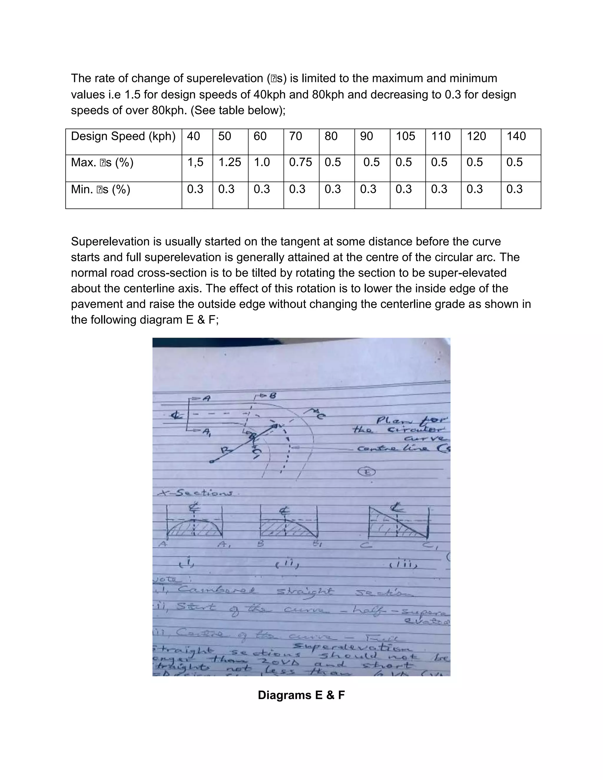
SlideShare a Scribd company logo
1 of 15
HIGHWAY ENGINEERING 1
FACTORS CONTROLLING THE GEOMETRIC DESIGN ELEMENTS
1. TOPOGRAPHY, LAND USE, ETC
Topography and land use are major factors in the determining the physical location,
alignment, gradients, sight distances and cross-sections of a road. Generally the
topography of an area is fitted into one of the following three classifications:
i) Level terrain
ii) Rolling terrain
iii) Mountainous terrain
Each of these terrains has its effects on the stated elements and should be considered
separately. For example, in flat or level terrain, it may be okay to follow the natural
profile but drainage could be a real problem. Also long straight stretches are found in
level grounds where they may be unsafe for careless drivers (over speeding). In
mountainous sections grade curves (horizontal and vertical), sight distances, etc, may
be the major problems and must be considered carefully.
2. FUNCTIONAL CLASS OF THE ROAD AND CONTROL OF ACCESS
Usually, roads authorities (ministries and municipalities) classify roads according to their
functions. In Kenya, roads are classified as class A (trunk roads) to class E (access
roads). The design standards for each class are taken differently, for example; as
horizontal curves of trunk roads will have a larger radius and the grades will be more
gentle as compared to access roads.
Also frequency of junction on major roads is usually limited and should not be allowed
especially where entering or leaving vehicles will create hazards situation. In urban
areas they are classified as Highways, Avenues, streets, etc.
3. DESIGN SPEED
The design speed is the maximum safe speed that can be maintained over a specified
section of a road, when conditions are so favorable that the design features govern. A
proper choice of the particular design speed will have a considerable effect on the
design of such features as horizontal and vertical curves, safe stopping and passing
sight distances, and acceptable highway grades.
Note:
Little is gained by using design speed greater than is necessary for this purpose, only a
comparatively few drivers are benefited driving periods of light traffic.
Design speed ranges between 40kph to 140kph.
Where changes in terrain or other conditions dictate a change in design speed, such
change should be made over a sufficient distance to allow drivers to change their
speeds gradually.
The choice of design speed will depend on:-
i) Terrain ie level or mountainous
ii) Road class (A – E)
iii) Traffic volume and composition
iv) Cost of road reserve and construction standards
v) Aesthetic considerations (comfort and safety)
4. DESIGN VEHICLE
The size and power of vehicles will definitely affect the geometric design elements e.g
curves, grades and lane widths. The width of the vehicle naturally affects the width of a
lane, the length affects the turning radius (curves), height affects the overhead
clearance for bridges and underpasses and, weight affects the structural design.
5. TRAFFIC VOLUME (CAPACITY)
Capacity is the ability of a road to accommodate traffic under given circumstances.
Factors which must be taken into consideration in determining the circumstances are
the physical features of the road itself and the prevailing traffic conditions.
Depending on the factual data on traffic volumes to be accommodated, a decision must
be made on whether a single carriageway (two lanes) or a dual carriageway (four or
more lanes)will be designed if funds are available.
6. ENVIRONMENTAL CONSIDERATIONS
It should be noted that no road project is without both positive and negative effects on
the environment. Positive effects include good service to the relevant communities while
negative effects include air pollution and noise.
7. ROAD SAFETY
Road engineers should provide design features aimed at preventing accidents, and in
case they occur, reducing their severity (ie the above factors must be taken into
consideration
8. ECONOMIC CONSIDERATIONS
Relationships between the construction costs and benefits are a measure of justification
and, a deciding factor in determining the geometric features of design.
The main objective in highway design is to create a road of appropriate type with
dimensional values and alignment characteristics such that the current resulting design
service volume will be at least as great as the design volume.
Once a level of service has been chosen for design, the corresponding service volume
logically becomes the design service volume. This implies that if the traffic volume using
the road exceeds that value, the operating conditions will be inferior to the level of
service for which the road was designed.
The costs of a road include provision of the road reserve, road construction and
maintenance. The benefits include reduced operational costs, comfort to passengers,
time saving, etc.
ELEMENTS (FEATURES) OF GEOMETRIC DESIGN
1. HORIZONTAL ALIGNMENT:
The horizontal alignment is the direction and course of the centerline in plan. It consists
of the following elements: the straight; the circular curve; the transition curve; the
super-elevation; curve widening and the cross sections.
It should be noted that, the maximum comfortable speed on a horizontal curve is
primarily dependent upon the radius of the curve, the super-elevation, presence of extra
carriageway widths and the insertion of transition curves between the straights and the
curves.
Consequently, improper design of the above features will result in lower speeds, lower
capacity and high accident potential. All the features stated above are briefly explained
here below:
i). The Straight: this is the stretch in a road section between two curves. A long stretch
of a straight may be possible in flat areas but rarely so in rolling or mountainous terrain
(but could be unpractical and very expensive).
It has been noted that the straights, besides leading to excessive speeding (dangerous),
also increase the accident potential because of monotony and headlights glare.
(Diagram A below).
Diagram A
To control the length of straights, the following steps are used (in Kenya):
a). The maximum straight stretch should not exceed 20VD (m), where VD is the design
speed in kph.
b). The minimum straights between circular curves following the same direction
(Diagram B) should not be less than 6VD (m).
Diagram B
Note: This type of circular curves is not common and is accident potential.
ii). The Circular Curve: The horizontal curve is a curve in plan. A circular curve may be
described by either its radius (R) or its curvature (D). The degree of curvature is the
angle subtended by a circular arc at the centre of the circle of which the centre arc is a
part, the length of the arc being limited by a given chord, usually 30m long i.e;
Radius (R) and Degree of Curvature (see sketches below)
Radius (R) & Degree 0f Curvature (Ბ) Sketches
In Kenya, the radius of the curve is usually used to describe the size of horizontal
curves. For calculation of the minimum horizontal radius for any given design speed
(VD), the following equation is used:
R = VD2 / 127(e+µ) (m)
Where:
R = minimum curve radius (m)
VD = Design Speed (km/hr)
e = Superelevation (%) ie ≈ 0-6%
µ = Developed lateral coefficient of friction (≈ 0.1%)
Note: The radius of curvature varies between 0.17 at 40kph to 0.10 at 140kph.
Particular care should be taken to avoid sharp curves at the ends of long straights. The
following guidelines may be applied:
a) If L ≤ 500m, then R ≥ L
b) If L > 500m, then R ≥ R 500m
Where: L = Length of the straight &, R = Radius of the curve
The table below gives the minimum radius (m) depending on the design speed as given
(currently) by the MORPW.
Design
Speed (kph)
40 50 60 70 80 90 100 110 120 140
Min. Radius
(m)
60 100 160 250 350 450 600 750 1000 1400
iii). Transition Curves:
Transition curve is a spiral curve in plan provided to effect the transition of the horizontal
alignment from straight to circular curve to a straight gradually meaning the radius of
transition curve varies between infinity to R or R to infinity.
Objectives for providing transition curves:
1. To make it possible to pass from one curve to another, from a straight to a curve,
gradually introducing Centrifugal force.
2. To introduce super elevation gradually
3. To introduce extra widening gradually
4. To provide comfort for the driver that is to enable smooth vehicle operation on
road.
5. To enhance aesthetics of highways.
These curves are required for all curves with radius less than 2000m and at a design
speed of over 60kph.
Usually the transition path, varies depending on the speed vehicle, the radius of the
circular curve, the superelevation and the steering action of the driver. The radius of
transitional curve decreases gradually from infinitely at the tangent to the radius of the
circular curve intersection.
The major factors governing the transition curve design are :-
1. Radius of the circular curve (R)
2. Length of the transition curve (L)
The minimum length of the transition curve is therefore given by the expression given
below:
L = VD3 / (3.63).CR
Where:
L = minimum transition curve.
VD = Design speed (kph)
R = Circular Curve Radius
C = Radial Acceleration (0.3 – 0.6)
(see diagram C).
Diagram C
iv). Superelevation:
Superelevation is the tilting of the road or carriageway laterally so that it slopes towards
the centre of the curve. It is introduced on horizontal curves in order to counteract the
centrifugal acceleration forces. Usually when changing from a straight section to a
curved section, the vehicle is driven at reduced speeds for the safety as well as for the
comfort of the occupants. This is due to the fact that a force is acting on the vehicle that
tends to cause an outward skidding away from the centre of the curve.
In order to overcome this tendency of skidding and to maintain average speeds, it is
necessary to super-elevate the road i.e raise the outside edge.
Superelevation may be measured in ratio (1:n), in percentage (1:25 = 4%) or in tan α as
shown (diagram D) here below:-
Diagram D
Superelevation run-off: This is the change from a normal camber to a super-elevated
section and is a function of the design speed and the rate of superelevation (i.e the
difference in grade between the centerline profile and the edge of a single carriageway
lane).
The length required to accommodate superelevation runoff (Lo) is calculated from the
expression below;
Lo = (e – eo) . (w)
Ბs(max) 2 mm
Where:
Lo = Superelevation runoff
e = Superelevation on the circular curve
eo = Camber or Crossfall on the straight section (normal camber)
W = Carriageway width (m)
Ბs = Rate of change of superelevation (usually between 0.3 – 1.5)
Note: It is accepted that, for every combination of radius of curvature and the road
design speed, there is a particular rate of superelevation that exactly balances the
outward force i.e centrifugal force.
When the superelevation is insufficient to balance the outward force it is then necessary
for some traditional force (f) to be developed between the tyres and the road surface in
order to keep the vehicle from skidding laterally.
The rate of change of superelevation (Ბs) is limited to the maximum and minimum
values i.e 1.5 for design speeds of 40kph and 80kph and decreasing to 0.3 for design
speeds of over 80kph. (See table below);
Design Speed (kph) 40 50 60 70 80 90 105 110 120 140
Max. Ბs (%) 1,5 1.25 1.0 0.75 0.5 0.5 0.5 0.5 0.5 0.5
Min. Ბs (%) 0.3 0.3 0.3 0.3 0.3 0.3 0.3 0.3 0.3 0.3
Superelevation is usually started on the tangent at some distance before the curve
starts and full superelevation is generally attained at the centre of the circular arc. The
normal road cross-section is to be tilted by rotating the section to be super-elevated
about the centerline axis. The effect of this rotation is to lower the inside edge of the
pavement and raise the outside edge without changing the centerline grade as shown in
the following diagram E & F;
Diagrams E & F
Referring to the Cross sections in E & F;
Note:
i. This is Cambered Straight Section
ii. This is Start of the curve i.e half super-elevated
iii. Centre of the curve i.e Full superelevation
Note: Straight sections should not be longer than 20VD and short straights not less than
6VD (VD = Design speed).
v). Curve Widening
curve widening refers to the extra width of carriageway that is required on a ccurved
section of a road over and above that required on a straight section . the amount of
widening varies with the width of the carriageway on straights, the design speed and the
curve radius. The primary reasons for curve widening are:-
i. Vehicles in curves occupy a greater width of carriageway, since their rear wheels
track inside the front wheels (see diagram G).
ii. Drivers generally experience some difficulty in holding their vehicles in the centre
of the lanes as they tend to shy away from the carriageway edge (i.e the vehicle
seems to be pulled inwards).
Curve widening is an expensive exercise but extra widths of less than 0.50m would
serve no purpose. Therefore, the widening which is required on both sides of the
carriageway should be introduced at a uniform rate along the transition length from
normal camber to full superelevation.
Extra width ranges from 0.50m to 1.20m and is calculated as follows (refer to diagram
G):-
Diagram G
W = R – (R2 – L2)1/2
Where:
W = Extra Width (m)
R = Radius of the outer front wheel of the vehicle
r = Radius of the inner rear wheel
d = Lateral width between the wheels
L = Length of the wheel base
Therefore:
W = R – (r+d)
But (r+d) = (R2 – L2)1/2
∴ W = R - (R2 – L2)1/2
The following points should be noted when widening horizontal curves:
1. On simple circular curves, the total extra width should be applied to the inside of
the carriageway while the outside edge and the centerline are both kept as
concentric circular arcs.
2. When transition curves are provided, before and after a simple circular curve, the
widening maybe equally divided between the inside and the outside of the curve
or it may be wholly applied to the inside edge of the carriageway.
3. The extra width should always be attained gradually and never abruptly, to
ensure that the entire carriageway is usable.
4. From an aesthetic point of view, the edges of the carriageway should at all times
form smooth and graceful curves.
Diagram H
Diagram (I)

More Related Content

Similar to HIGHWAY ENGINEERING 1 (ii).doc

1. ii Highway Alignment,, Engineering Survey and feasibility study.pdf
1. ii Highway Alignment,, Engineering Survey and feasibility study.pdf1. ii Highway Alignment,, Engineering Survey and feasibility study.pdf
1. ii Highway Alignment,, Engineering Survey and feasibility study.pdfEr. Bam Bhandari
 
Case Study on Highway Geometry for Two Lane Highway
Case Study on Highway Geometry for Two Lane HighwayCase Study on Highway Geometry for Two Lane Highway
Case Study on Highway Geometry for Two Lane HighwayIRJET Journal
 
geometric design ppt unit 3 (1).ppt
geometric design ppt unit 3 (1).pptgeometric design ppt unit 3 (1).ppt
geometric design ppt unit 3 (1).pptGate20241
 
1_Highway Engg-Ch.1 Introduction_full.pdf
1_Highway Engg-Ch.1 Introduction_full.pdf1_Highway Engg-Ch.1 Introduction_full.pdf
1_Highway Engg-Ch.1 Introduction_full.pdfShivamKumar423966
 
Sight distance and road allignment
Sight distance and road allignmentSight distance and road allignment
Sight distance and road allignmentPiter Biswas
 
Geometric design of highway
Geometric design of highwayGeometric design of highway
Geometric design of highwayJunaid Jamadar
 
intro to alignment.pptx
intro to alignment.pptxintro to alignment.pptx
intro to alignment.pptxCIVILSWATHI
 
Highway design presentation (Malyar Talash)
Highway design presentation (Malyar Talash)Highway design presentation (Malyar Talash)
Highway design presentation (Malyar Talash)Malyar Talash
 
Case Study on Geometry of Four Lane Highway
Case Study on Geometry of Four Lane HighwayCase Study on Geometry of Four Lane Highway
Case Study on Geometry of Four Lane HighwayIRJET Journal
 
Highway Horizontal Alignment
Highway Horizontal AlignmentHighway Horizontal Alignment
Highway Horizontal AlignmentAkshathaBhandary
 
2. Geometric Design of Highways.pdf
2. Geometric Design of Highways.pdf2. Geometric Design of Highways.pdf
2. Geometric Design of Highways.pdfEr. Bam Bhandari
 
Design Methodology for Feasible Railway Alignment
Design Methodology for Feasible Railway AlignmentDesign Methodology for Feasible Railway Alignment
Design Methodology for Feasible Railway AlignmentIRJET Journal
 
Geometric design of roads - Highways - Copy.docx
Geometric design of roads - Highways - Copy.docxGeometric design of roads - Highways - Copy.docx
Geometric design of roads - Highways - Copy.docxsydneyaugust1
 
Geometric design of roads - Highways.docx
Geometric design of roads - Highways.docxGeometric design of roads - Highways.docx
Geometric design of roads - Highways.docxsydneyaugust1
 

Similar to HIGHWAY ENGINEERING 1 (ii).doc (20)

R E T 565construction Technology Infrastructure
R E T 565construction Technology InfrastructureR E T 565construction Technology Infrastructure
R E T 565construction Technology Infrastructure
 
Construction Technology
Construction TechnologyConstruction Technology
Construction Technology
 
1. ii Highway Alignment,, Engineering Survey and feasibility study.pdf
1. ii Highway Alignment,, Engineering Survey and feasibility study.pdf1. ii Highway Alignment,, Engineering Survey and feasibility study.pdf
1. ii Highway Alignment,, Engineering Survey and feasibility study.pdf
 
Ch 4
Ch 4Ch 4
Ch 4
 
Case Study on Highway Geometry for Two Lane Highway
Case Study on Highway Geometry for Two Lane HighwayCase Study on Highway Geometry for Two Lane Highway
Case Study on Highway Geometry for Two Lane Highway
 
geometric design ppt unit 3 (1).ppt
geometric design ppt unit 3 (1).pptgeometric design ppt unit 3 (1).ppt
geometric design ppt unit 3 (1).ppt
 
Geometric design
Geometric designGeometric design
Geometric design
 
1_Highway Engg-Ch.1 Introduction_full.pdf
1_Highway Engg-Ch.1 Introduction_full.pdf1_Highway Engg-Ch.1 Introduction_full.pdf
1_Highway Engg-Ch.1 Introduction_full.pdf
 
Sight distance and road allignment
Sight distance and road allignmentSight distance and road allignment
Sight distance and road allignment
 
Geometric design of highway
Geometric design of highwayGeometric design of highway
Geometric design of highway
 
CH-2 highway.docx
CH-2 highway.docxCH-2 highway.docx
CH-2 highway.docx
 
intro to alignment.pptx
intro to alignment.pptxintro to alignment.pptx
intro to alignment.pptx
 
Highway design presentation (Malyar Talash)
Highway design presentation (Malyar Talash)Highway design presentation (Malyar Talash)
Highway design presentation (Malyar Talash)
 
Case Study on Geometry of Four Lane Highway
Case Study on Geometry of Four Lane HighwayCase Study on Geometry of Four Lane Highway
Case Study on Geometry of Four Lane Highway
 
Highway Horizontal Alignment
Highway Horizontal AlignmentHighway Horizontal Alignment
Highway Horizontal Alignment
 
2. Geometric Design of Highways.pdf
2. Geometric Design of Highways.pdf2. Geometric Design of Highways.pdf
2. Geometric Design of Highways.pdf
 
Design Methodology for Feasible Railway Alignment
Design Methodology for Feasible Railway AlignmentDesign Methodology for Feasible Railway Alignment
Design Methodology for Feasible Railway Alignment
 
Railway engineering
Railway engineeringRailway engineering
Railway engineering
 
Geometric design of roads - Highways - Copy.docx
Geometric design of roads - Highways - Copy.docxGeometric design of roads - Highways - Copy.docx
Geometric design of roads - Highways - Copy.docx
 
Geometric design of roads - Highways.docx
Geometric design of roads - Highways.docxGeometric design of roads - Highways.docx
Geometric design of roads - Highways.docx
 

Recently uploaded

Architect Hassan Khalil Portfolio for 2024
Architect Hassan Khalil Portfolio for 2024Architect Hassan Khalil Portfolio for 2024
Architect Hassan Khalil Portfolio for 2024hassan khalil
 
Microscopic Analysis of Ceramic Materials.pptx
Microscopic Analysis of Ceramic Materials.pptxMicroscopic Analysis of Ceramic Materials.pptx
Microscopic Analysis of Ceramic Materials.pptxpurnimasatapathy1234
 
Current Transformer Drawing and GTP for MSETCL
Current Transformer Drawing and GTP for MSETCLCurrent Transformer Drawing and GTP for MSETCL
Current Transformer Drawing and GTP for MSETCLDeelipZope
 
High Profile Call Girls Nagpur Isha Call 7001035870 Meet With Nagpur Escorts
High Profile Call Girls Nagpur Isha Call 7001035870 Meet With Nagpur EscortsHigh Profile Call Girls Nagpur Isha Call 7001035870 Meet With Nagpur Escorts
High Profile Call Girls Nagpur Isha Call 7001035870 Meet With Nagpur Escortsranjana rawat
 
Application of Residue Theorem to evaluate real integrations.pptx
Application of Residue Theorem to evaluate real integrations.pptxApplication of Residue Theorem to evaluate real integrations.pptx
Application of Residue Theorem to evaluate real integrations.pptx959SahilShah
 
chaitra-1.pptx fake news detection using machine learning
chaitra-1.pptx  fake news detection using machine learningchaitra-1.pptx  fake news detection using machine learning
chaitra-1.pptx fake news detection using machine learningmisbanausheenparvam
 
Artificial-Intelligence-in-Electronics (K).pptx
Artificial-Intelligence-in-Electronics (K).pptxArtificial-Intelligence-in-Electronics (K).pptx
Artificial-Intelligence-in-Electronics (K).pptxbritheesh05
 
Software and Systems Engineering Standards: Verification and Validation of Sy...
Software and Systems Engineering Standards: Verification and Validation of Sy...Software and Systems Engineering Standards: Verification and Validation of Sy...
Software and Systems Engineering Standards: Verification and Validation of Sy...VICTOR MAESTRE RAMIREZ
 
College Call Girls Nashik Nehal 7001305949 Independent Escort Service Nashik
College Call Girls Nashik Nehal 7001305949 Independent Escort Service NashikCollege Call Girls Nashik Nehal 7001305949 Independent Escort Service Nashik
College Call Girls Nashik Nehal 7001305949 Independent Escort Service NashikCall Girls in Nagpur High Profile
 
Past, Present and Future of Generative AI
Past, Present and Future of Generative AIPast, Present and Future of Generative AI
Past, Present and Future of Generative AIabhishek36461
 
Gfe Mayur Vihar Call Girls Service WhatsApp -> 9999965857 Available 24x7 ^ De...
Gfe Mayur Vihar Call Girls Service WhatsApp -> 9999965857 Available 24x7 ^ De...Gfe Mayur Vihar Call Girls Service WhatsApp -> 9999965857 Available 24x7 ^ De...
Gfe Mayur Vihar Call Girls Service WhatsApp -> 9999965857 Available 24x7 ^ De...srsj9000
 
Decoding Kotlin - Your guide to solving the mysterious in Kotlin.pptx
Decoding Kotlin - Your guide to solving the mysterious in Kotlin.pptxDecoding Kotlin - Your guide to solving the mysterious in Kotlin.pptx
Decoding Kotlin - Your guide to solving the mysterious in Kotlin.pptxJoão Esperancinha
 
Oxy acetylene welding presentation note.
Oxy acetylene welding presentation note.Oxy acetylene welding presentation note.
Oxy acetylene welding presentation note.eptoze12
 
What are the advantages and disadvantages of membrane structures.pptx
What are the advantages and disadvantages of membrane structures.pptxWhat are the advantages and disadvantages of membrane structures.pptx
What are the advantages and disadvantages of membrane structures.pptxwendy cai
 
Call Girls Delhi {Jodhpur} 9711199012 high profile service
Call Girls Delhi {Jodhpur} 9711199012 high profile serviceCall Girls Delhi {Jodhpur} 9711199012 high profile service
Call Girls Delhi {Jodhpur} 9711199012 high profile servicerehmti665
 
Introduction to Microprocesso programming and interfacing.pptx
Introduction to Microprocesso programming and interfacing.pptxIntroduction to Microprocesso programming and interfacing.pptx
Introduction to Microprocesso programming and interfacing.pptxvipinkmenon1
 
Internship report on mechanical engineering
Internship report on mechanical engineeringInternship report on mechanical engineering
Internship report on mechanical engineeringmalavadedarshan25
 
Sachpazis Costas: Geotechnical Engineering: A student's Perspective Introduction
Sachpazis Costas: Geotechnical Engineering: A student's Perspective IntroductionSachpazis Costas: Geotechnical Engineering: A student's Perspective Introduction
Sachpazis Costas: Geotechnical Engineering: A student's Perspective IntroductionDr.Costas Sachpazis
 

Recently uploaded (20)

Architect Hassan Khalil Portfolio for 2024
Architect Hassan Khalil Portfolio for 2024Architect Hassan Khalil Portfolio for 2024
Architect Hassan Khalil Portfolio for 2024
 
Microscopic Analysis of Ceramic Materials.pptx
Microscopic Analysis of Ceramic Materials.pptxMicroscopic Analysis of Ceramic Materials.pptx
Microscopic Analysis of Ceramic Materials.pptx
 
Current Transformer Drawing and GTP for MSETCL
Current Transformer Drawing and GTP for MSETCLCurrent Transformer Drawing and GTP for MSETCL
Current Transformer Drawing and GTP for MSETCL
 
High Profile Call Girls Nagpur Isha Call 7001035870 Meet With Nagpur Escorts
High Profile Call Girls Nagpur Isha Call 7001035870 Meet With Nagpur EscortsHigh Profile Call Girls Nagpur Isha Call 7001035870 Meet With Nagpur Escorts
High Profile Call Girls Nagpur Isha Call 7001035870 Meet With Nagpur Escorts
 
Application of Residue Theorem to evaluate real integrations.pptx
Application of Residue Theorem to evaluate real integrations.pptxApplication of Residue Theorem to evaluate real integrations.pptx
Application of Residue Theorem to evaluate real integrations.pptx
 
young call girls in Rajiv Chowk🔝 9953056974 🔝 Delhi escort Service
young call girls in Rajiv Chowk🔝 9953056974 🔝 Delhi escort Serviceyoung call girls in Rajiv Chowk🔝 9953056974 🔝 Delhi escort Service
young call girls in Rajiv Chowk🔝 9953056974 🔝 Delhi escort Service
 
chaitra-1.pptx fake news detection using machine learning
chaitra-1.pptx  fake news detection using machine learningchaitra-1.pptx  fake news detection using machine learning
chaitra-1.pptx fake news detection using machine learning
 
Artificial-Intelligence-in-Electronics (K).pptx
Artificial-Intelligence-in-Electronics (K).pptxArtificial-Intelligence-in-Electronics (K).pptx
Artificial-Intelligence-in-Electronics (K).pptx
 
Software and Systems Engineering Standards: Verification and Validation of Sy...
Software and Systems Engineering Standards: Verification and Validation of Sy...Software and Systems Engineering Standards: Verification and Validation of Sy...
Software and Systems Engineering Standards: Verification and Validation of Sy...
 
College Call Girls Nashik Nehal 7001305949 Independent Escort Service Nashik
College Call Girls Nashik Nehal 7001305949 Independent Escort Service NashikCollege Call Girls Nashik Nehal 7001305949 Independent Escort Service Nashik
College Call Girls Nashik Nehal 7001305949 Independent Escort Service Nashik
 
Past, Present and Future of Generative AI
Past, Present and Future of Generative AIPast, Present and Future of Generative AI
Past, Present and Future of Generative AI
 
Gfe Mayur Vihar Call Girls Service WhatsApp -> 9999965857 Available 24x7 ^ De...
Gfe Mayur Vihar Call Girls Service WhatsApp -> 9999965857 Available 24x7 ^ De...Gfe Mayur Vihar Call Girls Service WhatsApp -> 9999965857 Available 24x7 ^ De...
Gfe Mayur Vihar Call Girls Service WhatsApp -> 9999965857 Available 24x7 ^ De...
 
Call Us -/9953056974- Call Girls In Vikaspuri-/- Delhi NCR
Call Us -/9953056974- Call Girls In Vikaspuri-/- Delhi NCRCall Us -/9953056974- Call Girls In Vikaspuri-/- Delhi NCR
Call Us -/9953056974- Call Girls In Vikaspuri-/- Delhi NCR
 
Decoding Kotlin - Your guide to solving the mysterious in Kotlin.pptx
Decoding Kotlin - Your guide to solving the mysterious in Kotlin.pptxDecoding Kotlin - Your guide to solving the mysterious in Kotlin.pptx
Decoding Kotlin - Your guide to solving the mysterious in Kotlin.pptx
 
Oxy acetylene welding presentation note.
Oxy acetylene welding presentation note.Oxy acetylene welding presentation note.
Oxy acetylene welding presentation note.
 
What are the advantages and disadvantages of membrane structures.pptx
What are the advantages and disadvantages of membrane structures.pptxWhat are the advantages and disadvantages of membrane structures.pptx
What are the advantages and disadvantages of membrane structures.pptx
 
Call Girls Delhi {Jodhpur} 9711199012 high profile service
Call Girls Delhi {Jodhpur} 9711199012 high profile serviceCall Girls Delhi {Jodhpur} 9711199012 high profile service
Call Girls Delhi {Jodhpur} 9711199012 high profile service
 
Introduction to Microprocesso programming and interfacing.pptx
Introduction to Microprocesso programming and interfacing.pptxIntroduction to Microprocesso programming and interfacing.pptx
Introduction to Microprocesso programming and interfacing.pptx
 
Internship report on mechanical engineering
Internship report on mechanical engineeringInternship report on mechanical engineering
Internship report on mechanical engineering
 
Sachpazis Costas: Geotechnical Engineering: A student's Perspective Introduction
Sachpazis Costas: Geotechnical Engineering: A student's Perspective IntroductionSachpazis Costas: Geotechnical Engineering: A student's Perspective Introduction
Sachpazis Costas: Geotechnical Engineering: A student's Perspective Introduction
 

HIGHWAY ENGINEERING 1 (ii).doc

  • 1. HIGHWAY ENGINEERING 1 FACTORS CONTROLLING THE GEOMETRIC DESIGN ELEMENTS 1. TOPOGRAPHY, LAND USE, ETC Topography and land use are major factors in the determining the physical location, alignment, gradients, sight distances and cross-sections of a road. Generally the topography of an area is fitted into one of the following three classifications: i) Level terrain ii) Rolling terrain iii) Mountainous terrain Each of these terrains has its effects on the stated elements and should be considered separately. For example, in flat or level terrain, it may be okay to follow the natural profile but drainage could be a real problem. Also long straight stretches are found in level grounds where they may be unsafe for careless drivers (over speeding). In mountainous sections grade curves (horizontal and vertical), sight distances, etc, may be the major problems and must be considered carefully. 2. FUNCTIONAL CLASS OF THE ROAD AND CONTROL OF ACCESS Usually, roads authorities (ministries and municipalities) classify roads according to their functions. In Kenya, roads are classified as class A (trunk roads) to class E (access roads). The design standards for each class are taken differently, for example; as horizontal curves of trunk roads will have a larger radius and the grades will be more gentle as compared to access roads. Also frequency of junction on major roads is usually limited and should not be allowed especially where entering or leaving vehicles will create hazards situation. In urban areas they are classified as Highways, Avenues, streets, etc. 3. DESIGN SPEED The design speed is the maximum safe speed that can be maintained over a specified section of a road, when conditions are so favorable that the design features govern. A proper choice of the particular design speed will have a considerable effect on the design of such features as horizontal and vertical curves, safe stopping and passing sight distances, and acceptable highway grades. Note:
  • 2. Little is gained by using design speed greater than is necessary for this purpose, only a comparatively few drivers are benefited driving periods of light traffic. Design speed ranges between 40kph to 140kph. Where changes in terrain or other conditions dictate a change in design speed, such change should be made over a sufficient distance to allow drivers to change their speeds gradually. The choice of design speed will depend on:- i) Terrain ie level or mountainous ii) Road class (A – E) iii) Traffic volume and composition iv) Cost of road reserve and construction standards v) Aesthetic considerations (comfort and safety) 4. DESIGN VEHICLE The size and power of vehicles will definitely affect the geometric design elements e.g curves, grades and lane widths. The width of the vehicle naturally affects the width of a lane, the length affects the turning radius (curves), height affects the overhead clearance for bridges and underpasses and, weight affects the structural design. 5. TRAFFIC VOLUME (CAPACITY) Capacity is the ability of a road to accommodate traffic under given circumstances. Factors which must be taken into consideration in determining the circumstances are the physical features of the road itself and the prevailing traffic conditions. Depending on the factual data on traffic volumes to be accommodated, a decision must be made on whether a single carriageway (two lanes) or a dual carriageway (four or more lanes)will be designed if funds are available. 6. ENVIRONMENTAL CONSIDERATIONS It should be noted that no road project is without both positive and negative effects on the environment. Positive effects include good service to the relevant communities while negative effects include air pollution and noise. 7. ROAD SAFETY
  • 3. Road engineers should provide design features aimed at preventing accidents, and in case they occur, reducing their severity (ie the above factors must be taken into consideration 8. ECONOMIC CONSIDERATIONS Relationships between the construction costs and benefits are a measure of justification and, a deciding factor in determining the geometric features of design. The main objective in highway design is to create a road of appropriate type with dimensional values and alignment characteristics such that the current resulting design service volume will be at least as great as the design volume. Once a level of service has been chosen for design, the corresponding service volume logically becomes the design service volume. This implies that if the traffic volume using the road exceeds that value, the operating conditions will be inferior to the level of service for which the road was designed. The costs of a road include provision of the road reserve, road construction and maintenance. The benefits include reduced operational costs, comfort to passengers, time saving, etc.
  • 4. ELEMENTS (FEATURES) OF GEOMETRIC DESIGN 1. HORIZONTAL ALIGNMENT: The horizontal alignment is the direction and course of the centerline in plan. It consists of the following elements: the straight; the circular curve; the transition curve; the super-elevation; curve widening and the cross sections. It should be noted that, the maximum comfortable speed on a horizontal curve is primarily dependent upon the radius of the curve, the super-elevation, presence of extra carriageway widths and the insertion of transition curves between the straights and the curves. Consequently, improper design of the above features will result in lower speeds, lower capacity and high accident potential. All the features stated above are briefly explained here below: i). The Straight: this is the stretch in a road section between two curves. A long stretch of a straight may be possible in flat areas but rarely so in rolling or mountainous terrain (but could be unpractical and very expensive). It has been noted that the straights, besides leading to excessive speeding (dangerous), also increase the accident potential because of monotony and headlights glare. (Diagram A below). Diagram A To control the length of straights, the following steps are used (in Kenya): a). The maximum straight stretch should not exceed 20VD (m), where VD is the design speed in kph.
  • 5. b). The minimum straights between circular curves following the same direction (Diagram B) should not be less than 6VD (m). Diagram B Note: This type of circular curves is not common and is accident potential. ii). The Circular Curve: The horizontal curve is a curve in plan. A circular curve may be described by either its radius (R) or its curvature (D). The degree of curvature is the angle subtended by a circular arc at the centre of the circle of which the centre arc is a part, the length of the arc being limited by a given chord, usually 30m long i.e; Radius (R) and Degree of Curvature (see sketches below) Radius (R) & Degree 0f Curvature (Ბ) Sketches
  • 6. In Kenya, the radius of the curve is usually used to describe the size of horizontal curves. For calculation of the minimum horizontal radius for any given design speed (VD), the following equation is used: R = VD2 / 127(e+µ) (m) Where: R = minimum curve radius (m) VD = Design Speed (km/hr) e = Superelevation (%) ie ≈ 0-6% µ = Developed lateral coefficient of friction (≈ 0.1%) Note: The radius of curvature varies between 0.17 at 40kph to 0.10 at 140kph. Particular care should be taken to avoid sharp curves at the ends of long straights. The following guidelines may be applied: a) If L ≤ 500m, then R ≥ L b) If L > 500m, then R ≥ R 500m Where: L = Length of the straight &, R = Radius of the curve The table below gives the minimum radius (m) depending on the design speed as given (currently) by the MORPW. Design Speed (kph) 40 50 60 70 80 90 100 110 120 140 Min. Radius (m) 60 100 160 250 350 450 600 750 1000 1400 iii). Transition Curves: Transition curve is a spiral curve in plan provided to effect the transition of the horizontal alignment from straight to circular curve to a straight gradually meaning the radius of transition curve varies between infinity to R or R to infinity. Objectives for providing transition curves: 1. To make it possible to pass from one curve to another, from a straight to a curve, gradually introducing Centrifugal force.
  • 7. 2. To introduce super elevation gradually 3. To introduce extra widening gradually 4. To provide comfort for the driver that is to enable smooth vehicle operation on road. 5. To enhance aesthetics of highways. These curves are required for all curves with radius less than 2000m and at a design speed of over 60kph. Usually the transition path, varies depending on the speed vehicle, the radius of the circular curve, the superelevation and the steering action of the driver. The radius of transitional curve decreases gradually from infinitely at the tangent to the radius of the circular curve intersection. The major factors governing the transition curve design are :- 1. Radius of the circular curve (R) 2. Length of the transition curve (L) The minimum length of the transition curve is therefore given by the expression given below: L = VD3 / (3.63).CR Where: L = minimum transition curve. VD = Design speed (kph) R = Circular Curve Radius C = Radial Acceleration (0.3 – 0.6) (see diagram C).
  • 8. Diagram C iv). Superelevation: Superelevation is the tilting of the road or carriageway laterally so that it slopes towards the centre of the curve. It is introduced on horizontal curves in order to counteract the centrifugal acceleration forces. Usually when changing from a straight section to a curved section, the vehicle is driven at reduced speeds for the safety as well as for the comfort of the occupants. This is due to the fact that a force is acting on the vehicle that tends to cause an outward skidding away from the centre of the curve. In order to overcome this tendency of skidding and to maintain average speeds, it is necessary to super-elevate the road i.e raise the outside edge. Superelevation may be measured in ratio (1:n), in percentage (1:25 = 4%) or in tan α as shown (diagram D) here below:-
  • 9. Diagram D Superelevation run-off: This is the change from a normal camber to a super-elevated section and is a function of the design speed and the rate of superelevation (i.e the difference in grade between the centerline profile and the edge of a single carriageway lane). The length required to accommodate superelevation runoff (Lo) is calculated from the expression below; Lo = (e – eo) . (w) Ბs(max) 2 mm Where: Lo = Superelevation runoff e = Superelevation on the circular curve eo = Camber or Crossfall on the straight section (normal camber) W = Carriageway width (m) Ბs = Rate of change of superelevation (usually between 0.3 – 1.5) Note: It is accepted that, for every combination of radius of curvature and the road design speed, there is a particular rate of superelevation that exactly balances the outward force i.e centrifugal force. When the superelevation is insufficient to balance the outward force it is then necessary for some traditional force (f) to be developed between the tyres and the road surface in order to keep the vehicle from skidding laterally.
  • 10. The rate of change of superelevation (Ბs) is limited to the maximum and minimum values i.e 1.5 for design speeds of 40kph and 80kph and decreasing to 0.3 for design speeds of over 80kph. (See table below); Design Speed (kph) 40 50 60 70 80 90 105 110 120 140 Max. Ბs (%) 1,5 1.25 1.0 0.75 0.5 0.5 0.5 0.5 0.5 0.5 Min. Ბs (%) 0.3 0.3 0.3 0.3 0.3 0.3 0.3 0.3 0.3 0.3 Superelevation is usually started on the tangent at some distance before the curve starts and full superelevation is generally attained at the centre of the circular arc. The normal road cross-section is to be tilted by rotating the section to be super-elevated about the centerline axis. The effect of this rotation is to lower the inside edge of the pavement and raise the outside edge without changing the centerline grade as shown in the following diagram E & F; Diagrams E & F
  • 11. Referring to the Cross sections in E & F; Note: i. This is Cambered Straight Section ii. This is Start of the curve i.e half super-elevated iii. Centre of the curve i.e Full superelevation Note: Straight sections should not be longer than 20VD and short straights not less than 6VD (VD = Design speed). v). Curve Widening curve widening refers to the extra width of carriageway that is required on a ccurved section of a road over and above that required on a straight section . the amount of widening varies with the width of the carriageway on straights, the design speed and the curve radius. The primary reasons for curve widening are:- i. Vehicles in curves occupy a greater width of carriageway, since their rear wheels track inside the front wheels (see diagram G). ii. Drivers generally experience some difficulty in holding their vehicles in the centre of the lanes as they tend to shy away from the carriageway edge (i.e the vehicle seems to be pulled inwards). Curve widening is an expensive exercise but extra widths of less than 0.50m would serve no purpose. Therefore, the widening which is required on both sides of the carriageway should be introduced at a uniform rate along the transition length from normal camber to full superelevation. Extra width ranges from 0.50m to 1.20m and is calculated as follows (refer to diagram G):-
  • 12. Diagram G W = R – (R2 – L2)1/2 Where: W = Extra Width (m) R = Radius of the outer front wheel of the vehicle r = Radius of the inner rear wheel d = Lateral width between the wheels L = Length of the wheel base Therefore: W = R – (r+d) But (r+d) = (R2 – L2)1/2 ∴ W = R - (R2 – L2)1/2
  • 13. The following points should be noted when widening horizontal curves: 1. On simple circular curves, the total extra width should be applied to the inside of the carriageway while the outside edge and the centerline are both kept as concentric circular arcs. 2. When transition curves are provided, before and after a simple circular curve, the widening maybe equally divided between the inside and the outside of the curve or it may be wholly applied to the inside edge of the carriageway. 3. The extra width should always be attained gradually and never abruptly, to ensure that the entire carriageway is usable. 4. From an aesthetic point of view, the edges of the carriageway should at all times form smooth and graceful curves.