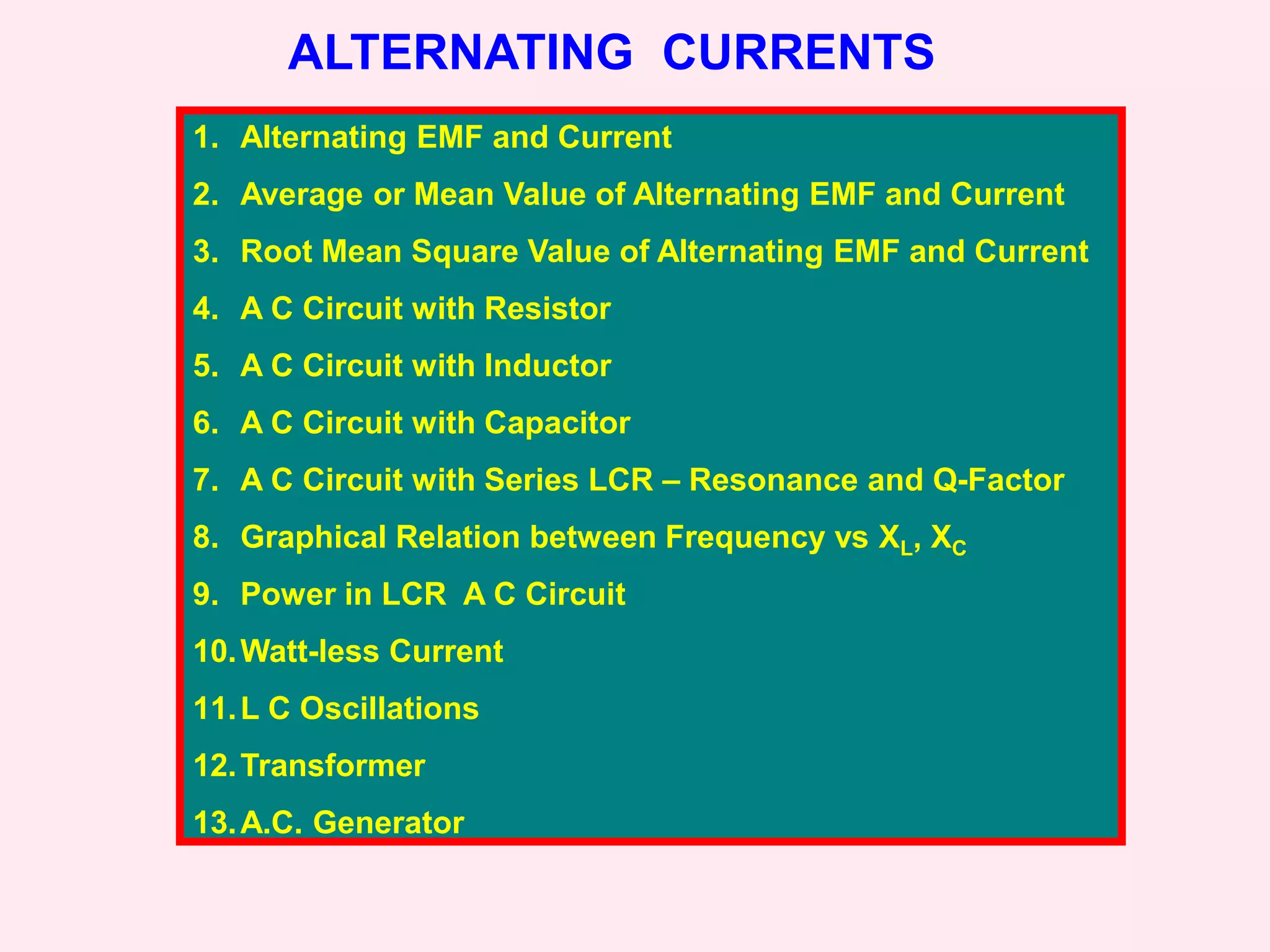
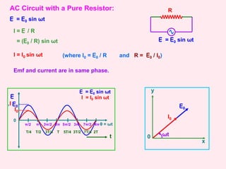
This document discusses alternating current (AC) circuits. It covers:
1. The definitions and characteristics of alternating current and voltage, including their instantaneous, average, and root mean square values.
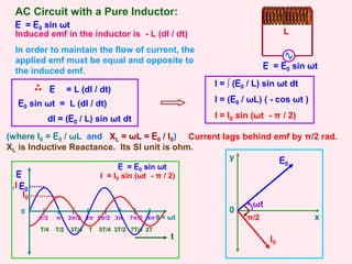
2. AC circuits with resistors, inductors, and capacitors individually, including how current and voltage are related in each.
3. Series LCR circuits, including how impedance, current, voltage, and phase angle are related. Resonance in LCR circuits and the concept of quality factor are also introduced.
4. Power calculations and concepts in AC circuits like active power, reactive power, power factor, and wattless current.
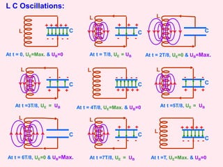
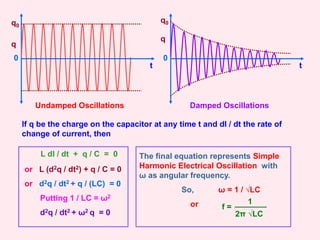
5. Oscillations in LC circuits and
![y
AC Circuit with a Capacitor:
E = E0 sin ωt
E = E0 sin ωt
T/4 T/2 3T/4 T 5T/4 3T/2 7T/4 2T
t
0
π 2π 3π 4π
π/2 3π/2 5π/2 7π/2 θ = ωt
E
,I E0
I0
E = E0 sin ωt
I = I0 sin (ωt + π / 2)
E0
ωt
q = CE = CE0 sin ωt
I = dq / dt
= (d / dt) [CE0 sin ωt]
I = [E0 / (1 / ωC)] ( cos ωt )
I = I0 sin (ωt + π / 2)
(where I0 = E0 / (1 / ωC) and
XC = 1 / ωC = E0 / I0)
XC is Capacitive Reactance.
Its SI unit is ohm.
I0
π/2
x
0
Current leads the emf by π/2 radians.
C](https://image.slidesharecdn.com/2alternatingcurrents-230119202246-e7c68266/85/2_alternating_currents-ppt-9-320.jpg)
![AC Circuit with L, C, R in Series
Combination:
E = E0 sin ωt
C
L R
VL
VC
VR
1) In R, current and voltage are in
phase.
2) In L, current lags behind voltage by
π/2
3) In C, current leads the voltage by
π/2 VR
VL
VC
I
π/2
π/2
- VC
VL
VR
I
π/2
VL - VC
VR
I
E
Φ
E = √ [VR
2 + (VL –
VC)2]
The applied emf appears as
Voltage drops VR, VL and VC
across R, L and C respectively.
E = √ [VR
2 + (VL – VC)2]
I =
E
√ [R2 + (XL – XC)2]
Z = √ [R2 + (XL – XC)2]
Z = √ [R2 + (ω L – 1/ωC)2]
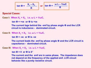
tan Φ =
XL – XC
R
tan Φ =
ω L – 1/ωC
R
or
0
VC](https://image.slidesharecdn.com/2alternatingcurrents-230119202246-e7c68266/85/2_alternating_currents-ppt-11-320.jpg)
![Resonance in AC Circuit with L, C, R:
When XL = XC i.e. ω L = 1/ωC, tan Φ = 0 or Φ is 0° and
Z = √ [R2 + (ω L – 1/ωC)2] becomes Zmin = R and I0max = E / R
i.e. The impedance offered by the circuit is minimum and the
current is maximum. This condition is called resonant condition
of LCR circuit and the frequency is called resonant frequency.
At resonant angular frequency ωr,
ωr L = 1/ωrC or ωr = 1 / √LC or fr = 1 / (2π √LC)
ωr
I0max
ω
0
R1
R2
R3
I0
I0max / √2
ωr - ∆ ω ωr + ∆ ω
Band width = 2 ∆ ω
Quality factor (Q – factor) is defined as the
ratio of resonant frequency to band width.
Q = ωr / 2 ∆ ω
or Q = ωr L / R or Q = 1 / ωrCR
Q = VL / VR or Q = VC / VR
Resonant Curve & Q - Factor:
It can also be defined as the ratio of potential
drop across either the inductance or the
capacitance to the potential drop across the
resistance.
R1 < R2 < R3](https://image.slidesharecdn.com/2alternatingcurrents-230119202246-e7c68266/85/2_alternating_currents-ppt-13-320.jpg)
![Power in AC Circuit with L, C, R:
Instantaneous Power = E I
= E0 I0 sin ωt sin (ωt + Φ)
= E0 I0 [sin2 ωt cosΦ + sin ωt cosωt cosΦ]
E = E0 sin ωt
I = I0 sin (ωt + Φ) (where Φ is the phase angle between emf and current)
If the instantaneous power is assumed to be constant for an
infinitesimally small time dt, then the work done is
dW = E0 I0 [sin2 ωt cosΦ + sin ωt cosωt cosΦ]
Work done over a complete cycle is
W = ∫ E0 I0 [sin2 ωt cosΦ + sin ωt cosωt cosΦ] dt
0
T
W = E0I0 cos Φ x T / 2
Average Power over a cycle is Pav = W / T
Pav = (E0I0/ 2) cos Φ
Pav = (E0/√2) (I0/ √2) cos Φ
(where cos Φ = R / Z
= R /√ [R2 + (ω L – 1/ωC)2]
is called Power Factor)
Pav = Ev Iv cos Φ](https://image.slidesharecdn.com/2alternatingcurrents-230119202246-e7c68266/85/2_alternating_currents-ppt-14-320.jpg)