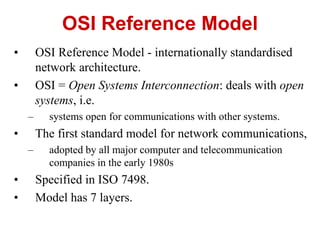
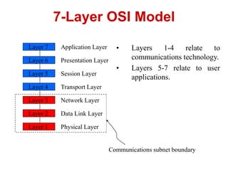
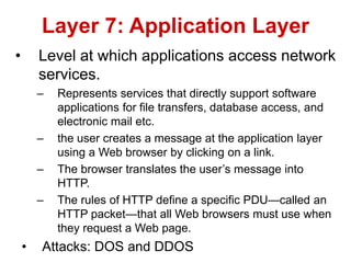
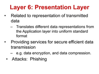
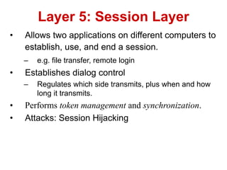
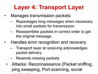
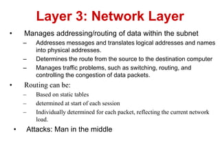
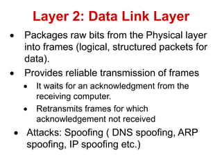
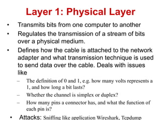
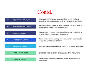
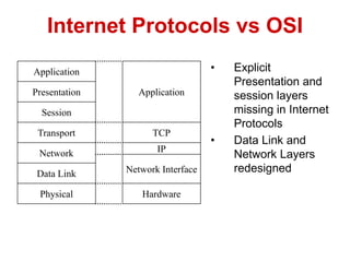
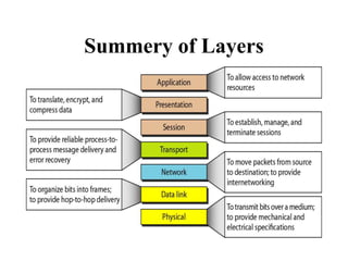
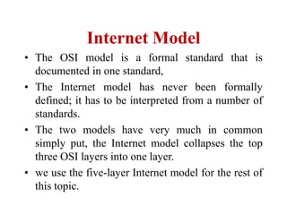
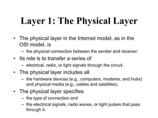
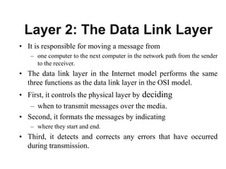
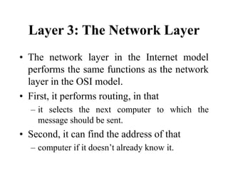
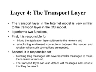
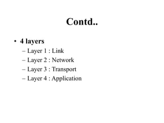
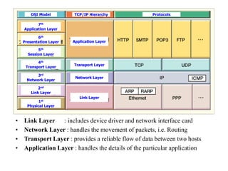
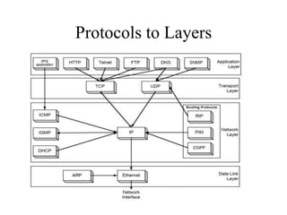
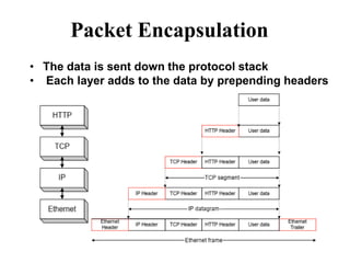
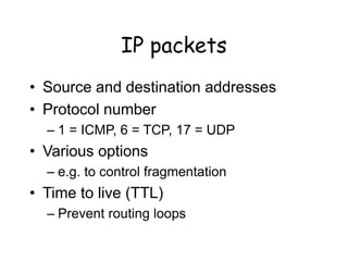
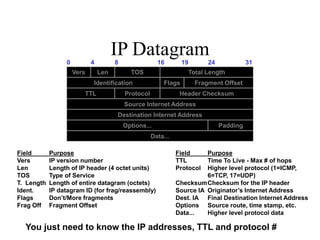
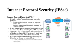
UNIT-VIII
Network Security Models
2.2
LAYERED TASKS
• We use the concept of layers in our daily life.
• As an example, let us consider two friends who
communicate through postal mail.
• The process of sending a letter to a friend
would be complex if there were no services
available from the post office.
• OSI Reference Model - internationally standardised
network architecture.
• OSI = Open Systems Interconnection: deals with open
systems, i.e.
– systems open for communications with other systems.
• The first standard model for network communications,
– adopted by all major computer and telecommunication
companies in the early 1980s
• Specified in ISO 7498.
• Model has 7 layers.
OSI Reference Model
• Layers 1-4 relate to
communications technology.
• Layers 5-7 relate to user
applications.
7-Layer OSI Model
Layer 7
Layer 6
Layer 5
Layer 4
Layer 3
Layer 2
Layer 1
Application Layer
Presentation Layer
Session Layer
Transport Layer
Network Layer
Data Link Layer
Physical Layer
Communications subnet boundary
• Level at which applications access network
services.
– Represents services that directly support software
applications for file transfers, database access, and
electronic mail etc.
– the user creates a message at the application layer
using a Web browser by clicking on a link.
– The browser translates the user’s message into
HTTP.
– The rules of HTTP define a specific PDU—called an
HTTP packet—that all Web browsers must use when
they request a Web page.
• Attacks: DOS and DDOS
Layer 7: Application Layer
• Related to representation of transmitted
data
– Translates different data representations from
the Application layer into uniform standard
format
• Providing services for secure efficient data
transmission
– e.g. data encryption, and data compression.
• Attacks: Phishing
Layer 6: Presentation Layer
• Allows two applications on different computers to
establish, use, and end a session.
– e.g. file transfer, remote login
• Establishes dialog control
– Regulates which side transmits, plus when and how
long it transmits.
• Performs token management and synchronization.
• Attacks: Session Hijacking
Layer 5: Session Layer
• Manages transmission packets
– Repackages long messages when necessary
into small packets for transmission
– Reassembles packets in correct order to get
the original message.
• Handles error recognition and recovery.
– Transport layer at receiving acknowledges
packet delivery.
– Resends missing packets
• Attacks: Reconnaissance (Packet sniffing,
ping sweeping, Port scanning, social
Layer 4: Transport Layer
• Manages addressing/routing of data within the subnet
– Addresses messages and translates logical addresses and names
into physical addresses.
– Determines the route from the source to the destination computer
– Manages traffic problems, such as switching, routing, and
controlling the congestion of data packets.
• Routing can be:
– Based on static tables
– determined at start of each session
– Individually determined for each packet, reflecting the current network
load.
• Attacks: Man in the middle
Layer 3: Network Layer
 Packages raw bits from the Physical layer
into frames (logical, structured packets for
data).
 Provides reliable transmission of frames
 It waits for an acknowledgment from the
receiving computer.
 Retransmits frames for which
acknowledgement not received
 Attacks: Spoofing ( DNS spoofing, ARP
spoofing, IP spoofing etc.)
Layer 2: Data Link Layer
• Transmits bits from one computer to another
• Regulates the transmission of a stream of bits
over a physical medium.
• Defines how the cable is attached to the network
adapter and what transmission technique is used
to send data over the cable. Deals with issues
like
– The definition of 0 and 1, e.g. how many volts represents a
1, and how long a bit lasts?
– Whether the channel is simplex or duplex?
– How many pins a connector has, and what the function of
each pin is?
• Attacks: Sniffing like application Wireshark, Tcpdump
Layer 1: Physical Layer
Contd..
• Explicit
Presentation and
session layers
missing in Internet
Protocols
• Data Link and
Network Layers
redesigned
Internet Protocols vs OSI
Application
Presentation
Session
Transport
Network
Data Link
Physical
Application
TCP
IP
Network Interface
Hardware
Summery of Layers
Internet Model
• The OSI model is a formal standard that is
documented in one standard,
• The Internet model has never been formally
defined; it has to be interpreted from a number of
standards.
• The two models have very much in common
simply put, the Internet model collapses the top
three OSI layers into one layer.
• we use the five-layer Internet model for the rest of
this topic.
Layer 1: The Physical Layer
• The physical layer in the Internet model, as in the
OSI model, is
– the physical connection between the sender and receiver.
• Its role is to transfer a series of
– electrical, radio, or light signals through the circuit.
• The physical layer includes all
– the hardware devices (e.g., computers, modems, and hubs)
and physical media (e.g., cables and satellites).
• The physical layer specifies
– the type of connection and
– the electrical signals, radio waves, or light pulses that pass
through it.
Layer 2: The Data Link Layer
• It is responsible for moving a message from
– one computer to the next computer in the network path from the sender
to the receiver.
• The data link layer in the Internet model performs the same
three functions as the data link layer in the OSI model.
• First, it controls the physical layer by deciding
– when to transmit messages over the media.
• Second, it formats the messages by indicating
– where they start and end.
• Third, it detects and corrects any errors that have occurred
during transmission.
Layer 3: The Network Layer
• The network layer in the Internet model
performs the same functions as the network
layer in the OSI model.
• First, it performs routing, in that
– it selects the next computer to which the
message should be sent.
• Second, it can find the address of that
– computer if it doesn’t already know it.
Layer 4: The Transport Layer
• The transport layer in the Internet model is very similar
to the transport layer in the OSI model.
• It performs two functions.
• First, it is responsible for
– linking the application layer software to the network and
– establishing end-to-end connections between the sender and
receiver when such connections are needed.
• Second, it is responsible for
– breaking long messages into several smaller messages to make
them easier to transmit.
– The transport layer can also detect lost messages and request
that they be resent.
Layer 5: Application Layer
• The application layer is the application software used by
the network user and includes much of what the OSI model
contains in the
– application, presentation, and session layers.
• It is the user’s access to the network.
• By using the application software, the user defines what
– messages are sent over the network.
– It discusses the architecture of network applications and
– several types of network application software and the types of
messages they generate.
Message Transmission Using Layers
TCP/IP REFERENCE Model
• four-layered suite of communication protocols.
• developed by the DoD (Department of
Defence) in the 1960s.
• Named after the two main protocols that
– TCP and IP.
• TCP stands for Transmission Control Protocol
and IP stands for Internet Protocol.
Contd..
• The four layers in the TCP/IP protocol suite
are −
• Host-to- Network Layer −
• It is the lowest layer that is concerned with
the physical transmission of data.
• TCP/IP does not specifically define any
protocol here but supports all the standard
protocols.
Contd..
• Internet Layer −
• It defines the protocols for logical
transmission of data over the network.
• The main protocol in this layer is
• Internet Protocol (IP) and
• it is supported by the protocols
• ICMP, ARP etc.
Contd..
• Transport Layer −
– It is responsible for error-free end-to-end delivery of
data.
– The protocols defined here are
• Transmission Control Protocol (TCP) and User Datagram
Protocol (UDP).
• Application Layer −
– This is the topmost layer and defines the interface of
host programs with the transport layer services.
– This layer includes all high-level protocols like Telnet,
DNS, HTTP, FTP, SMTP, etc.
Contd..
• 4 layers
– Layer 1 : Link
– Layer 2 : Network
– Layer 3 : Transport
– Layer 4 : Application
• Link Layer : includes device driver and network interface card
• Network Layer : handles the movement of packets, i.e. Routing
• Transport Layer : provides a reliable flow of data between two hosts
• Application Layer : handles the details of the particular application
OSI Model TCP/IP Hierarchy Protocols
7th
Application Layer
6th
Presentation Layer
5th
Session Layer
4th
Transport Layer
3rd
Network Layer
2nd
Link Layer
1st
Physical Layer
Application Layer
Transport Layer
Network Layer
Link Layer
Protocols to Layers
Packet Encapsulation
• The data is sent down the protocol stack
• Each layer adds to the data by prepending headers
IP
• Responsible for end to end transmission
• Sends data in individual packets
• Maximum size of packet is determined
by the networks
– Fragmented if too large
• Unreliable
– Packets might be lost, corrupted,
duplicated, delivered out of order
Routing
• How does a device know where to send
a packet?
– All devices need to know what IP
addresses are on directly attached
networks
– If the destination is on a local network,
send it directly there
Routing (cont)
• If the destination address isn’t local
– Most non-router devices just send
everything to a single local router
– Routers need to know which network
corresponds to each possible IP address
Allocation of addresses
• Controlled centrally by ICANN
– Fairly strict rules on further delegation to
avoid wastage
• Have to demonstrate actual need for them
• Organizations that got in early have
bigger allocations than they really need
IP packets
• Source and destination addresses
• Protocol number
– 1 = ICMP, 6 = TCP, 17 = UDP
• Various options
– e.g. to control fragmentation
• Time to live (TTL)
– Prevent routing loops
IP Datagram
Vers Len TOS Total Length
Identification Flags Fragment Offset
TTL Protocol Header Checksum
Source Internet Address
Destination Internet Address
Options... Padding
Data...
0 4 8 16 19 24 31
Field Purpose
Vers IP version number
Len Length of IP header (4 octet units)
TOS Type of Service
T. Length Length of entire datagram (octets)
Ident. IP datagram ID (for frag/reassembly)
Flags Don’t/More fragments
Frag Off Fragment Offset
Field Purpose
TTL Time To Live - Max # of hops
Protocol Higher level protocol (1=ICMP,
6=TCP, 17=UDP)
ChecksumChecksum for the IP header
Source IA Originator’s Internet Address
Dest. IA Final Destination Internet Address
Options Source route, time stamp, etc.
Data... Higher level protocol data
You just need to know the IP addresses, TTL and protocol #
Security in the Transport Layer
• These protocols are at the level below the
application layer.
– Two Socket layer
• Secure Socket Layer (SSL) and
• Transport Layer Security (TLS).
• These two are no longer considered as two separate
protocols but one under the name SSL/TLS,
– after the SSL standardization was passed over to IETF,
by the Netscape consortium, and
– Internet Engineering Task Force (IETF) renamed it
TLS.
Secure Socket Layer (SSL)
• SSL is a widely used general purpose cryptographic
system used in the two major Internet browsers
Netscape and Explorer.
• It provides an encrypted end-to-end data path between a
client and a server regardless of platform or OS.
• Secure and authenticated services are provided through
– data encryption,
– server authentication,
– message integrity, and
– client authentication for a TCP connection through HTTP,
LDAP or POP3 application layers.
Contd..
• Transport Layer Security (TLS)
– TLS is the result of the 1996 Internet Engineering Task Force (IETF)
attempt at standardization of a secure method to communicate over the
Web.
– 1999 outcome of that attempt was released as RFC 2246 spelling out a
new protocol-
• the Transport Layer Security or TLS.
– TLS was charged with providing security and data integrity at the
transport layer between two applications.
– TLS version 1.0 was an evolved SSL 3.0. Frequently, the new standard is
referred to as SSL/TLS.
– Since then, however, the following additional features have been added
• Interoperability - ability to exchange TLS parameters by either party, with no need
for one party to know the others TLS implementation details.
• Expandability to plan for future expansions and accommodation of new protocols
Security in the Network Layer
• These protocols also address Internet
communication security.
• These protocols include IPSec and VPN
technologies.
Internet Protocol Security (IPSec)
• Internet Protocol Security (IPSec)
– IPSec is a suite of authentication and encryption
protocols
• developed by the Internet Engineering Task Force
(IETF) and
• designed to address the inherent lack of security for
IP-based networks.
– IPSec, has a very complex set of protocols described
in a number of RFCs including RFC 2401 and 2411.
– Although it was designed to run in the new version
of the Internet Protocol, IP Version 6 (IPv6), it has
also successfully run in the older IPv4 as well.
– IPSec sets out to offer protection by providing the
following services at the network layer
• Access Control to prevent an unauthorized access to
the resource.
Contd..
– Connectionless Integrity to give an assurance that the
traffic received has not been modified in any way.
– Confidentiality to ensure that Internet traffic is not
examined by non-authorized parties.
• This requires all IP datagrams to have their data field, TCP, UDP,
ICMP or any other datagram data field segment, encrypted.
– Authentication particularly source authentication so that
when a destination host receives an IP datagram, with a
particular IP source address, it is possible to be sure that the
IP datagram was indeed generated by the host with the
source IP address.
• This prevents spoofed IP addresses.
– Replay protection to guarantee that each packet exchanged
between two parties is different.
Contd..
• IPSec protocol achieves these objectives by dividing
the protocol suite into two main protocols
Authentication Header (AH) protocol and the
Encapsulation Security Payload (ESP)protocol.
• The AH protocol provides source authentication and
data integrity but no confidentiality.
• The ESP protocol provides authentication, data
integrity, and confidentiality.
• Any datagram from a source must be secured with
either AH or ESP.
Contd..
– IPSec protocol achieves these objectives by
dividing the protocol suite into two main protocols
• Authentication Header (AH) protocol and
• the Encapsulation Security Payload (ESP) protocol.
– The AH protocol provides source authentication
and data integrity but no confidentiality.
– The ESP protocol provides authentication, data
integrity, and confidentiality.
– Any datagram from a source must be secured with
either AH or ESP.
Contd..
– IPSec operates in two modes transport and
tunnel
– Transport mode
• The Transport mode provides host-to-host protection
to higher layer protocols in the communication
between two hosts in both IPv4 and IPv6.
– In IPv4, this area is the area beyond the IP
address.
– In IPv6, the new extensions to IPv4, the
protection includes the upper protocols
Contd..
– Tunnel mode
– Tunnel mode offers protection to the entire IP datagram both in AH
and ESP between two IPSec gateways.
– This is possible because of the added new IP header in both IPv4
and IPv6. Between the two gateways, the datagram is secure and
the original IP address is also secure.
• However, beyond the gateways, the datagram may not be
secure.
– Such protection is created when the first IPSec gateway
encapsulate the datagram including its IP address into a new shield
datagram with a new IP address of the receiving IPSec gateway.
– At the receiving gateway, the new datagram is unwrapped and
brought back to the original datagram
IP Security Architecture
1. Architecture:
Architecture or IP Security
Architecture covers the general
concepts, definitions, protocols,
algorithms and security
requirements of IP Security
technology.
2. ESP Protocol:
ESP(Encapsulation Security
Payload) provide the
confidentiality service.
Encapsulation Security Payload is
implemented in either two ways:
1. ESP with optional
Authentication.
2. ESP with Authentication.
Packet Format
•Security Parameter Index(SPI):
This parameter is used in Security Association. It is used to
give a unique number to the connection build between Client
and Server.
•Sequence Number:
Unique Sequence number are allotted to every packet so
that at the receiver side packets can be arranged properly.
•Payload Data:
Payload data means the actual data or the actual message.
The Payload data is in encrypted format to achieve
confidentiality.
•Padding:
Extra bits or space added to the original message in order to
ensure confidentiality. Padding length is the size of the
added bits or space in the original message.
•Next Header:
Next header means the next payload or next actual data.
•Authentication Data
This field is optional in ESP protocol packet format.
Contd..
3. Encryption algorithm:
Encryption algorithm is the document that
describes various encryption algorithm used
for Encapsulation Security Payload.
4. AH Protocol:
• AH (Authentication Header) Protocol
provides both Authentication and
Integrity service.
• Authentication Header is implemented in
one way only:
– Authentication along with Integrity.
• Authentication Header covers the packet
format and general issue related to the use of
AH for packet authentication and integrity.
Contd..
5. Authentication Algorithm:
– Authentication Algorithm contains the set of the
documents that describe authentication algorithm used
for AH and for the authentication option of ESP.
6. DOI (Domain of Interpretation):
– DOI is the identifier which support both AH and ESP
protocols. It contains values needed for documentation
related to each other.
7. Key Management:
– Key Management contains the document that describes
how the keys are exchanged between sender and
receiver.
Virtual Private Networks (VPN)
• Virtual Private Networks (VPN)
– A VPN is a private data network that makes use of the public
telecommunication infrastructure, such as the Internet, by adding
security procedures over the unsecure communication channels.
– The security procedures that involve encryption are achieved
through the use of a tunneling protocol.
– There are two types of VPNs remote access which lets single users
connect to the protected company network and site-to-site which
supports connections between two protected company networks.
– In either mode, VPN technology gives a company the facilities of
expensive private leased lines at much lower cost by using the
shared public infrastructure like the Internet.

OSI Model.ppt

  • 1.
  • 2.
    2.2 LAYERED TASKS • Weuse the concept of layers in our daily life. • As an example, let us consider two friends who communicate through postal mail. • The process of sending a letter to a friend would be complex if there were no services available from the post office.
  • 4.
    • OSI ReferenceModel - internationally standardised network architecture. • OSI = Open Systems Interconnection: deals with open systems, i.e. – systems open for communications with other systems. • The first standard model for network communications, – adopted by all major computer and telecommunication companies in the early 1980s • Specified in ISO 7498. • Model has 7 layers. OSI Reference Model
  • 5.
    • Layers 1-4relate to communications technology. • Layers 5-7 relate to user applications. 7-Layer OSI Model Layer 7 Layer 6 Layer 5 Layer 4 Layer 3 Layer 2 Layer 1 Application Layer Presentation Layer Session Layer Transport Layer Network Layer Data Link Layer Physical Layer Communications subnet boundary
  • 6.
    • Level atwhich applications access network services. – Represents services that directly support software applications for file transfers, database access, and electronic mail etc. – the user creates a message at the application layer using a Web browser by clicking on a link. – The browser translates the user’s message into HTTP. – The rules of HTTP define a specific PDU—called an HTTP packet—that all Web browsers must use when they request a Web page. • Attacks: DOS and DDOS Layer 7: Application Layer
  • 7.
    • Related torepresentation of transmitted data – Translates different data representations from the Application layer into uniform standard format • Providing services for secure efficient data transmission – e.g. data encryption, and data compression. • Attacks: Phishing Layer 6: Presentation Layer
  • 8.
    • Allows twoapplications on different computers to establish, use, and end a session. – e.g. file transfer, remote login • Establishes dialog control – Regulates which side transmits, plus when and how long it transmits. • Performs token management and synchronization. • Attacks: Session Hijacking Layer 5: Session Layer
  • 9.
    • Manages transmissionpackets – Repackages long messages when necessary into small packets for transmission – Reassembles packets in correct order to get the original message. • Handles error recognition and recovery. – Transport layer at receiving acknowledges packet delivery. – Resends missing packets • Attacks: Reconnaissance (Packet sniffing, ping sweeping, Port scanning, social Layer 4: Transport Layer
  • 10.
    • Manages addressing/routingof data within the subnet – Addresses messages and translates logical addresses and names into physical addresses. – Determines the route from the source to the destination computer – Manages traffic problems, such as switching, routing, and controlling the congestion of data packets. • Routing can be: – Based on static tables – determined at start of each session – Individually determined for each packet, reflecting the current network load. • Attacks: Man in the middle Layer 3: Network Layer
  • 11.
     Packages rawbits from the Physical layer into frames (logical, structured packets for data).  Provides reliable transmission of frames  It waits for an acknowledgment from the receiving computer.  Retransmits frames for which acknowledgement not received  Attacks: Spoofing ( DNS spoofing, ARP spoofing, IP spoofing etc.) Layer 2: Data Link Layer
  • 12.
    • Transmits bitsfrom one computer to another • Regulates the transmission of a stream of bits over a physical medium. • Defines how the cable is attached to the network adapter and what transmission technique is used to send data over the cable. Deals with issues like – The definition of 0 and 1, e.g. how many volts represents a 1, and how long a bit lasts? – Whether the channel is simplex or duplex? – How many pins a connector has, and what the function of each pin is? • Attacks: Sniffing like application Wireshark, Tcpdump Layer 1: Physical Layer
  • 13.
  • 14.
    • Explicit Presentation and sessionlayers missing in Internet Protocols • Data Link and Network Layers redesigned Internet Protocols vs OSI Application Presentation Session Transport Network Data Link Physical Application TCP IP Network Interface Hardware
  • 15.
  • 16.
    Internet Model • TheOSI model is a formal standard that is documented in one standard, • The Internet model has never been formally defined; it has to be interpreted from a number of standards. • The two models have very much in common simply put, the Internet model collapses the top three OSI layers into one layer. • we use the five-layer Internet model for the rest of this topic.
  • 17.
    Layer 1: ThePhysical Layer • The physical layer in the Internet model, as in the OSI model, is – the physical connection between the sender and receiver. • Its role is to transfer a series of – electrical, radio, or light signals through the circuit. • The physical layer includes all – the hardware devices (e.g., computers, modems, and hubs) and physical media (e.g., cables and satellites). • The physical layer specifies – the type of connection and – the electrical signals, radio waves, or light pulses that pass through it.
  • 18.
    Layer 2: TheData Link Layer • It is responsible for moving a message from – one computer to the next computer in the network path from the sender to the receiver. • The data link layer in the Internet model performs the same three functions as the data link layer in the OSI model. • First, it controls the physical layer by deciding – when to transmit messages over the media. • Second, it formats the messages by indicating – where they start and end. • Third, it detects and corrects any errors that have occurred during transmission.
  • 19.
    Layer 3: TheNetwork Layer • The network layer in the Internet model performs the same functions as the network layer in the OSI model. • First, it performs routing, in that – it selects the next computer to which the message should be sent. • Second, it can find the address of that – computer if it doesn’t already know it.
  • 20.
    Layer 4: TheTransport Layer • The transport layer in the Internet model is very similar to the transport layer in the OSI model. • It performs two functions. • First, it is responsible for – linking the application layer software to the network and – establishing end-to-end connections between the sender and receiver when such connections are needed. • Second, it is responsible for – breaking long messages into several smaller messages to make them easier to transmit. – The transport layer can also detect lost messages and request that they be resent.
  • 21.
    Layer 5: ApplicationLayer • The application layer is the application software used by the network user and includes much of what the OSI model contains in the – application, presentation, and session layers. • It is the user’s access to the network. • By using the application software, the user defines what – messages are sent over the network. – It discusses the architecture of network applications and – several types of network application software and the types of messages they generate.
  • 22.
  • 23.
    TCP/IP REFERENCE Model •four-layered suite of communication protocols. • developed by the DoD (Department of Defence) in the 1960s. • Named after the two main protocols that – TCP and IP. • TCP stands for Transmission Control Protocol and IP stands for Internet Protocol.
  • 24.
    Contd.. • The fourlayers in the TCP/IP protocol suite are − • Host-to- Network Layer − • It is the lowest layer that is concerned with the physical transmission of data. • TCP/IP does not specifically define any protocol here but supports all the standard protocols.
  • 25.
    Contd.. • Internet Layer− • It defines the protocols for logical transmission of data over the network. • The main protocol in this layer is • Internet Protocol (IP) and • it is supported by the protocols • ICMP, ARP etc.
  • 26.
    Contd.. • Transport Layer− – It is responsible for error-free end-to-end delivery of data. – The protocols defined here are • Transmission Control Protocol (TCP) and User Datagram Protocol (UDP). • Application Layer − – This is the topmost layer and defines the interface of host programs with the transport layer services. – This layer includes all high-level protocols like Telnet, DNS, HTTP, FTP, SMTP, etc.
  • 27.
    Contd.. • 4 layers –Layer 1 : Link – Layer 2 : Network – Layer 3 : Transport – Layer 4 : Application
  • 28.
    • Link Layer: includes device driver and network interface card • Network Layer : handles the movement of packets, i.e. Routing • Transport Layer : provides a reliable flow of data between two hosts • Application Layer : handles the details of the particular application OSI Model TCP/IP Hierarchy Protocols 7th Application Layer 6th Presentation Layer 5th Session Layer 4th Transport Layer 3rd Network Layer 2nd Link Layer 1st Physical Layer Application Layer Transport Layer Network Layer Link Layer
  • 29.
  • 30.
    Packet Encapsulation • Thedata is sent down the protocol stack • Each layer adds to the data by prepending headers
  • 31.
    IP • Responsible forend to end transmission • Sends data in individual packets • Maximum size of packet is determined by the networks – Fragmented if too large • Unreliable – Packets might be lost, corrupted, duplicated, delivered out of order
  • 32.
    Routing • How doesa device know where to send a packet? – All devices need to know what IP addresses are on directly attached networks – If the destination is on a local network, send it directly there
  • 33.
    Routing (cont) • Ifthe destination address isn’t local – Most non-router devices just send everything to a single local router – Routers need to know which network corresponds to each possible IP address
  • 34.
    Allocation of addresses •Controlled centrally by ICANN – Fairly strict rules on further delegation to avoid wastage • Have to demonstrate actual need for them • Organizations that got in early have bigger allocations than they really need
  • 35.
    IP packets • Sourceand destination addresses • Protocol number – 1 = ICMP, 6 = TCP, 17 = UDP • Various options – e.g. to control fragmentation • Time to live (TTL) – Prevent routing loops
  • 36.
    IP Datagram Vers LenTOS Total Length Identification Flags Fragment Offset TTL Protocol Header Checksum Source Internet Address Destination Internet Address Options... Padding Data... 0 4 8 16 19 24 31 Field Purpose Vers IP version number Len Length of IP header (4 octet units) TOS Type of Service T. Length Length of entire datagram (octets) Ident. IP datagram ID (for frag/reassembly) Flags Don’t/More fragments Frag Off Fragment Offset Field Purpose TTL Time To Live - Max # of hops Protocol Higher level protocol (1=ICMP, 6=TCP, 17=UDP) ChecksumChecksum for the IP header Source IA Originator’s Internet Address Dest. IA Final Destination Internet Address Options Source route, time stamp, etc. Data... Higher level protocol data You just need to know the IP addresses, TTL and protocol #
  • 37.
    Security in theTransport Layer • These protocols are at the level below the application layer. – Two Socket layer • Secure Socket Layer (SSL) and • Transport Layer Security (TLS). • These two are no longer considered as two separate protocols but one under the name SSL/TLS, – after the SSL standardization was passed over to IETF, by the Netscape consortium, and – Internet Engineering Task Force (IETF) renamed it TLS.
  • 38.
    Secure Socket Layer(SSL) • SSL is a widely used general purpose cryptographic system used in the two major Internet browsers Netscape and Explorer. • It provides an encrypted end-to-end data path between a client and a server regardless of platform or OS. • Secure and authenticated services are provided through – data encryption, – server authentication, – message integrity, and – client authentication for a TCP connection through HTTP, LDAP or POP3 application layers.
  • 39.
    Contd.. • Transport LayerSecurity (TLS) – TLS is the result of the 1996 Internet Engineering Task Force (IETF) attempt at standardization of a secure method to communicate over the Web. – 1999 outcome of that attempt was released as RFC 2246 spelling out a new protocol- • the Transport Layer Security or TLS. – TLS was charged with providing security and data integrity at the transport layer between two applications. – TLS version 1.0 was an evolved SSL 3.0. Frequently, the new standard is referred to as SSL/TLS. – Since then, however, the following additional features have been added • Interoperability - ability to exchange TLS parameters by either party, with no need for one party to know the others TLS implementation details. • Expandability to plan for future expansions and accommodation of new protocols
  • 40.
    Security in theNetwork Layer • These protocols also address Internet communication security. • These protocols include IPSec and VPN technologies.
  • 41.
    Internet Protocol Security(IPSec) • Internet Protocol Security (IPSec) – IPSec is a suite of authentication and encryption protocols • developed by the Internet Engineering Task Force (IETF) and • designed to address the inherent lack of security for IP-based networks. – IPSec, has a very complex set of protocols described in a number of RFCs including RFC 2401 and 2411. – Although it was designed to run in the new version of the Internet Protocol, IP Version 6 (IPv6), it has also successfully run in the older IPv4 as well. – IPSec sets out to offer protection by providing the following services at the network layer • Access Control to prevent an unauthorized access to the resource.
  • 42.
    Contd.. – Connectionless Integrityto give an assurance that the traffic received has not been modified in any way. – Confidentiality to ensure that Internet traffic is not examined by non-authorized parties. • This requires all IP datagrams to have their data field, TCP, UDP, ICMP or any other datagram data field segment, encrypted. – Authentication particularly source authentication so that when a destination host receives an IP datagram, with a particular IP source address, it is possible to be sure that the IP datagram was indeed generated by the host with the source IP address. • This prevents spoofed IP addresses. – Replay protection to guarantee that each packet exchanged between two parties is different.
  • 43.
    Contd.. • IPSec protocolachieves these objectives by dividing the protocol suite into two main protocols Authentication Header (AH) protocol and the Encapsulation Security Payload (ESP)protocol. • The AH protocol provides source authentication and data integrity but no confidentiality. • The ESP protocol provides authentication, data integrity, and confidentiality. • Any datagram from a source must be secured with either AH or ESP.
  • 44.
    Contd.. – IPSec protocolachieves these objectives by dividing the protocol suite into two main protocols • Authentication Header (AH) protocol and • the Encapsulation Security Payload (ESP) protocol. – The AH protocol provides source authentication and data integrity but no confidentiality. – The ESP protocol provides authentication, data integrity, and confidentiality. – Any datagram from a source must be secured with either AH or ESP.
  • 45.
    Contd.. – IPSec operatesin two modes transport and tunnel – Transport mode • The Transport mode provides host-to-host protection to higher layer protocols in the communication between two hosts in both IPv4 and IPv6. – In IPv4, this area is the area beyond the IP address. – In IPv6, the new extensions to IPv4, the protection includes the upper protocols
  • 46.
    Contd.. – Tunnel mode –Tunnel mode offers protection to the entire IP datagram both in AH and ESP between two IPSec gateways. – This is possible because of the added new IP header in both IPv4 and IPv6. Between the two gateways, the datagram is secure and the original IP address is also secure. • However, beyond the gateways, the datagram may not be secure. – Such protection is created when the first IPSec gateway encapsulate the datagram including its IP address into a new shield datagram with a new IP address of the receiving IPSec gateway. – At the receiving gateway, the new datagram is unwrapped and brought back to the original datagram
  • 47.
    IP Security Architecture 1.Architecture: Architecture or IP Security Architecture covers the general concepts, definitions, protocols, algorithms and security requirements of IP Security technology. 2. ESP Protocol: ESP(Encapsulation Security Payload) provide the confidentiality service. Encapsulation Security Payload is implemented in either two ways: 1. ESP with optional Authentication. 2. ESP with Authentication.
  • 48.
    Packet Format •Security ParameterIndex(SPI): This parameter is used in Security Association. It is used to give a unique number to the connection build between Client and Server. •Sequence Number: Unique Sequence number are allotted to every packet so that at the receiver side packets can be arranged properly. •Payload Data: Payload data means the actual data or the actual message. The Payload data is in encrypted format to achieve confidentiality. •Padding: Extra bits or space added to the original message in order to ensure confidentiality. Padding length is the size of the added bits or space in the original message. •Next Header: Next header means the next payload or next actual data. •Authentication Data This field is optional in ESP protocol packet format.
  • 49.
    Contd.. 3. Encryption algorithm: Encryptionalgorithm is the document that describes various encryption algorithm used for Encapsulation Security Payload. 4. AH Protocol: • AH (Authentication Header) Protocol provides both Authentication and Integrity service. • Authentication Header is implemented in one way only: – Authentication along with Integrity. • Authentication Header covers the packet format and general issue related to the use of AH for packet authentication and integrity.
  • 50.
    Contd.. 5. Authentication Algorithm: –Authentication Algorithm contains the set of the documents that describe authentication algorithm used for AH and for the authentication option of ESP. 6. DOI (Domain of Interpretation): – DOI is the identifier which support both AH and ESP protocols. It contains values needed for documentation related to each other. 7. Key Management: – Key Management contains the document that describes how the keys are exchanged between sender and receiver.
  • 51.
    Virtual Private Networks(VPN) • Virtual Private Networks (VPN) – A VPN is a private data network that makes use of the public telecommunication infrastructure, such as the Internet, by adding security procedures over the unsecure communication channels. – The security procedures that involve encryption are achieved through the use of a tunneling protocol. – There are two types of VPNs remote access which lets single users connect to the protected company network and site-to-site which supports connections between two protected company networks. – In either mode, VPN technology gives a company the facilities of expensive private leased lines at much lower cost by using the shared public infrastructure like the Internet.