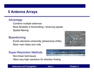
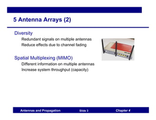
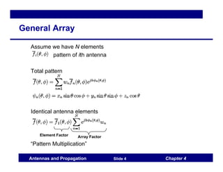
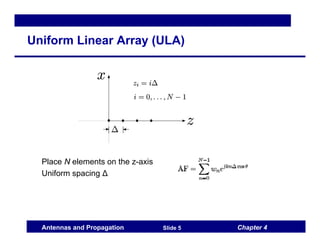
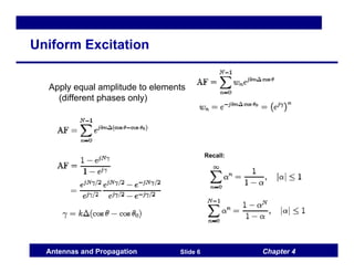
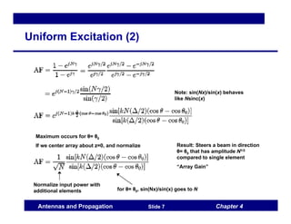
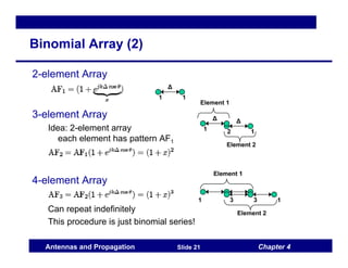
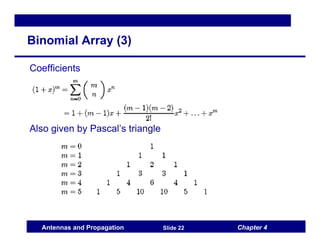
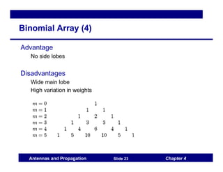
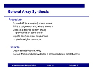
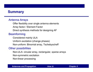
Chapter 5: Antenna Arrays
Antennas and Propagation
Chapter 4
Antennas and Propagation Slide 2
5 Antenna Arrays
Advantage
Combine multiple antennas
More flexibility in transmitting / receiving signals
Spatial filtering
Beamforming
Excite elements coherently (phase/amp shifts)
Steer main lobes and nulls
Super-Resolution Methods
Non-linear techniques
Allow very high resolution for direction finding
Chapter 4
Antennas and Propagation Slide 3
5 Antenna Arrays (2)
Diversity
Redundant signals on multiple antennas
Reduce effects due to channel fading
Spatial Multiplexing (MIMO)
Different information on multiple antennas
Increase system throughput (capacity)
Chapter 4
Antennas and Propagation Slide 4
General Array
Assume we have N elements
pattern of ith antenna
Total pattern
Identical antenna elements
“Pattern Multiplication”
Element Factor Array Factor
Chapter 4
Antennas and Propagation Slide 5
Uniform Linear Array (ULA)
Place N elements on the z-axis
Uniform spacing Δ
Chapter 4
Antennas and Propagation Slide 6
Uniform Excitation
Apply equal amplitude to elements
(different phases only)
Recall:
Chapter 4
Antennas and Propagation Slide 7
Uniform Excitation (2)
Note: sin(Nx)/sin(x) behaves
like Nsinc(x)
Maximum occurs for θ= θ0
If we center array about z=0, and normalize
Normalize input power with
additional elements for θ= θ0, sin(Nx)/sin(x) goes to N
Result: Steers a beam in direction
θ= θ0 that has amplitude N1/2
compared to single element
“Array Gain”
Chapter 4
Antennas and Propagation Slide 8
Uniform Excitation: Examples
Example: N=8, Δ=λ/2
Chapter 4
Antennas and Propagation Slide 9
Grating Lobes
Problem for Δ > λ/2
Lobes with amplitude equal to main beam appear
Called “grating lobes”
Similar to aliasing in signal processing
Example
Chapter 4
Antennas and Propagation Slide 10
ULA Beamwidth, Directivity
Note: Example values in (.) are for N=8, Δ=λ/2
Chapter 4
Antennas and Propagation Slide 11
Hansen-Woodyard (HWA)
Idea
End-fire excitation has a fat main lobe
Simple coherent excitation not optimal solution for directivity
HWA: do direct maximization
Analysis
Array factor for N elements and progressive phase shift β
Max max AF = 1
Chapter 4
Antennas and Propagation Slide 12
Hansen-Woodyard (2)
Consider small
Means scan angle on “main beam”
Progressive phase shift
Chapter 4
Antennas and Propagation Slide 13
Hansen-Woodyard (3)
Radiation intensity: proportional to |AF|2
In beam direction, θ=0, U(θ) is
Normalize U to make unity at θ=0. Call new function U′(θ)
Directivity found as D0=4πUmax/Prad = Umax/U0, with
How do we maximize D0?
Chapter 4
Antennas and Propagation Slide 14
Hansen-Woodyard (4)
Minimize
Find v, then can compute β
Chapter 4
Antennas and Propagation Slide 15
Hansen-Woodyard (5)
vmin = -1.46
Chapter 4
Antennas and Propagation Slide 16
Hansen-Woodyard (6)
Directivity of HWA:
Is there a cost to increased directivity?
Chapter 4
Antennas and Propagation Slide 17
Non-Uniform Excitation
Increased Flexibility
Weights are general
Similar to a filter synthesis problem
Example methods
Binomial Array
Similar to “maximally flat” filter
No side lobes for Δ < λ/2
Tschebyscheff Array
Similar to “equiripple” filter
Produces smallest beamwidth
for given sidelobe level
Chapter 4
Antennas and Propagation Slide 18
Symmetric Array
Antennas placed symmetrically on ±z axis
(Also same excitation)
Odd number of elements:
put two copies of center element (for two sides)
Amplitude on true center
element is 2a1
Chapter 4
Antennas and Propagation Slide 19
Symmetric Array (2)
Array factors are
Example Methods
Binomial array
Derive based on heuristic argument
Tschebyscheff array
Use direct synthesis procedure
Chapter 4
Antennas and Propagation Slide 20
Binomial Array
2-element Array
Plot of AF1 = 1 + x
Has no side-lobes for Δ < λ/2
Idea to make more dir.
Successively superimpose
pairs of arrays
Generates AF = (AF1)M
Δ
Chapter 4
Antennas and Propagation Slide 21
Binomial Array (2)
2-element Array
3-element Array
Idea: 2-element array
each element has pattern AF1
4-element Array
Can repeat indefinitely
This procedure is just binomial series!
Δ
Δ
Element 1
Element 2
1 2 1
Δ
1 1
1 3 3 1
Element 1
Element 2
Chapter 4
Antennas and Propagation Slide 22
Binomial Array (3)
Coefficients
Also given by Pascal’s triangle
Chapter 4
Antennas and Propagation Slide 23
Binomial Array (4)
Advantage
No side lobes
Disadvantages
Wide main lobe
High variation in weights
Chapter 4
Antennas and Propagation Slide 24
General Array Synthesis
Procedure
Expand AF in a (cosine) power series
AF is a polynomial in x, where x=cos u
Choose a desired pattern shape
(polynomial of same order)
Equate coefficients of polynomials
⇒ yields weights on arrays
Example
Dolph-Tschebyscheff Array
Solves: Minimum beamwidth for a prescribed max. sidelobe level
Chapter 4
Antennas and Propagation Slide 25
Tschebyscheff Array
Array factor
Even number of antennas (M is twice # antennas)
Cosine Power Series
Chapter 4
Antennas and Propagation Slide 26
Tschebyscheff Array (2)
Tschebyscheff Polynomials
Recursion
Direct Computation with cos/cosh
Chapter 4
Antennas and Propagation Slide 27
Tschebyscheff Array (3)
Tschebyscheff Polynomials
Chapter 4
Antennas and Propagation Slide 28
Tschebyscheff Example
M = 3 (6 antenna elements)
Chapter 4
Antennas and Propagation Slide 29
Tschebyscheff Example (2)
OK, but
How do we map z to x?
Chapter 4
Antennas and Propagation Slide 30
Tschebyscheff Example (3)
Main beam at
x = 1 x = cos u
z = z0
Let z = z0 x
Chapter 4
Antennas and Propagation Slide 31
Tschebyscheff Example (4)
Straightforward generalization for higher orders.
Chapter 4
Antennas and Propagation Slide 32
Tschebyscheff Array (Generalized)
Chapter 4
Antennas and Propagation Slide 33
Gen. Tschebyscheff Array (2)
Can find the am using the same recursive procedure as before.
Chapter 4
Antennas and Propagation Slide 34
Comparison of Beamforming Methods
Δ=π/4, N=8, R0=10 (-20dB side lobes)
Chapter 4
Antennas and Propagation Slide 35
Summary
Antenna Arrays
Offer flexibility over single antenna elements
Array factor / Element Factor
Direct synthesis methods for designing AF
Beamforming
Considered mainly ULA
Uniform excitation (change phases)
Non-uniform: Binomial array, Tschebyscheff
Other possibilities
Non-ULA: circular array, rectangular, sparse arrays
Non-symmetric excitation
Non-linear processing

ch5 Antenna Arrays.pdf

  • 1.
    Chapter 5: AntennaArrays Antennas and Propagation
  • 2.
    Chapter 4 Antennas andPropagation Slide 2 5 Antenna Arrays Advantage Combine multiple antennas More flexibility in transmitting / receiving signals Spatial filtering Beamforming Excite elements coherently (phase/amp shifts) Steer main lobes and nulls Super-Resolution Methods Non-linear techniques Allow very high resolution for direction finding
  • 3.
    Chapter 4 Antennas andPropagation Slide 3 5 Antenna Arrays (2) Diversity Redundant signals on multiple antennas Reduce effects due to channel fading Spatial Multiplexing (MIMO) Different information on multiple antennas Increase system throughput (capacity)
  • 4.
    Chapter 4 Antennas andPropagation Slide 4 General Array Assume we have N elements pattern of ith antenna Total pattern Identical antenna elements “Pattern Multiplication” Element Factor Array Factor
  • 5.
    Chapter 4 Antennas andPropagation Slide 5 Uniform Linear Array (ULA) Place N elements on the z-axis Uniform spacing Δ
  • 6.
    Chapter 4 Antennas andPropagation Slide 6 Uniform Excitation Apply equal amplitude to elements (different phases only) Recall:
  • 7.
    Chapter 4 Antennas andPropagation Slide 7 Uniform Excitation (2) Note: sin(Nx)/sin(x) behaves like Nsinc(x) Maximum occurs for θ= θ0 If we center array about z=0, and normalize Normalize input power with additional elements for θ= θ0, sin(Nx)/sin(x) goes to N Result: Steers a beam in direction θ= θ0 that has amplitude N1/2 compared to single element “Array Gain”
  • 8.
    Chapter 4 Antennas andPropagation Slide 8 Uniform Excitation: Examples Example: N=8, Δ=λ/2
  • 9.
    Chapter 4 Antennas andPropagation Slide 9 Grating Lobes Problem for Δ > λ/2 Lobes with amplitude equal to main beam appear Called “grating lobes” Similar to aliasing in signal processing Example
  • 10.
    Chapter 4 Antennas andPropagation Slide 10 ULA Beamwidth, Directivity Note: Example values in (.) are for N=8, Δ=λ/2
  • 11.
    Chapter 4 Antennas andPropagation Slide 11 Hansen-Woodyard (HWA) Idea End-fire excitation has a fat main lobe Simple coherent excitation not optimal solution for directivity HWA: do direct maximization Analysis Array factor for N elements and progressive phase shift β Max max AF = 1
  • 12.
    Chapter 4 Antennas andPropagation Slide 12 Hansen-Woodyard (2) Consider small Means scan angle on “main beam” Progressive phase shift
  • 13.
    Chapter 4 Antennas andPropagation Slide 13 Hansen-Woodyard (3) Radiation intensity: proportional to |AF|2 In beam direction, θ=0, U(θ) is Normalize U to make unity at θ=0. Call new function U′(θ) Directivity found as D0=4πUmax/Prad = Umax/U0, with How do we maximize D0?
  • 14.
    Chapter 4 Antennas andPropagation Slide 14 Hansen-Woodyard (4) Minimize Find v, then can compute β
  • 15.
    Chapter 4 Antennas andPropagation Slide 15 Hansen-Woodyard (5) vmin = -1.46
  • 16.
    Chapter 4 Antennas andPropagation Slide 16 Hansen-Woodyard (6) Directivity of HWA: Is there a cost to increased directivity?
  • 17.
    Chapter 4 Antennas andPropagation Slide 17 Non-Uniform Excitation Increased Flexibility Weights are general Similar to a filter synthesis problem Example methods Binomial Array Similar to “maximally flat” filter No side lobes for Δ < λ/2 Tschebyscheff Array Similar to “equiripple” filter Produces smallest beamwidth for given sidelobe level
  • 18.
    Chapter 4 Antennas andPropagation Slide 18 Symmetric Array Antennas placed symmetrically on ±z axis (Also same excitation) Odd number of elements: put two copies of center element (for two sides) Amplitude on true center element is 2a1
  • 19.
    Chapter 4 Antennas andPropagation Slide 19 Symmetric Array (2) Array factors are Example Methods Binomial array Derive based on heuristic argument Tschebyscheff array Use direct synthesis procedure
  • 20.
    Chapter 4 Antennas andPropagation Slide 20 Binomial Array 2-element Array Plot of AF1 = 1 + x Has no side-lobes for Δ < λ/2 Idea to make more dir. Successively superimpose pairs of arrays Generates AF = (AF1)M Δ
  • 21.
    Chapter 4 Antennas andPropagation Slide 21 Binomial Array (2) 2-element Array 3-element Array Idea: 2-element array each element has pattern AF1 4-element Array Can repeat indefinitely This procedure is just binomial series! Δ Δ Element 1 Element 2 1 2 1 Δ 1 1 1 3 3 1 Element 1 Element 2
  • 22.
    Chapter 4 Antennas andPropagation Slide 22 Binomial Array (3) Coefficients Also given by Pascal’s triangle
  • 23.
    Chapter 4 Antennas andPropagation Slide 23 Binomial Array (4) Advantage No side lobes Disadvantages Wide main lobe High variation in weights
  • 24.
    Chapter 4 Antennas andPropagation Slide 24 General Array Synthesis Procedure Expand AF in a (cosine) power series AF is a polynomial in x, where x=cos u Choose a desired pattern shape (polynomial of same order) Equate coefficients of polynomials ⇒ yields weights on arrays Example Dolph-Tschebyscheff Array Solves: Minimum beamwidth for a prescribed max. sidelobe level
  • 25.
    Chapter 4 Antennas andPropagation Slide 25 Tschebyscheff Array Array factor Even number of antennas (M is twice # antennas) Cosine Power Series
  • 26.
    Chapter 4 Antennas andPropagation Slide 26 Tschebyscheff Array (2) Tschebyscheff Polynomials Recursion Direct Computation with cos/cosh
  • 27.
    Chapter 4 Antennas andPropagation Slide 27 Tschebyscheff Array (3) Tschebyscheff Polynomials
  • 28.
    Chapter 4 Antennas andPropagation Slide 28 Tschebyscheff Example M = 3 (6 antenna elements)
  • 29.
    Chapter 4 Antennas andPropagation Slide 29 Tschebyscheff Example (2) OK, but How do we map z to x?
  • 30.
    Chapter 4 Antennas andPropagation Slide 30 Tschebyscheff Example (3) Main beam at x = 1 x = cos u z = z0 Let z = z0 x
  • 31.
    Chapter 4 Antennas andPropagation Slide 31 Tschebyscheff Example (4) Straightforward generalization for higher orders.
  • 32.
    Chapter 4 Antennas andPropagation Slide 32 Tschebyscheff Array (Generalized)
  • 33.
    Chapter 4 Antennas andPropagation Slide 33 Gen. Tschebyscheff Array (2) Can find the am using the same recursive procedure as before.
  • 34.
    Chapter 4 Antennas andPropagation Slide 34 Comparison of Beamforming Methods Δ=π/4, N=8, R0=10 (-20dB side lobes)
  • 35.
    Chapter 4 Antennas andPropagation Slide 35 Summary Antenna Arrays Offer flexibility over single antenna elements Array factor / Element Factor Direct synthesis methods for designing AF Beamforming Considered mainly ULA Uniform excitation (change phases) Non-uniform: Binomial array, Tschebyscheff Other possibilities Non-ULA: circular array, rectangular, sparse arrays Non-symmetric excitation Non-linear processing