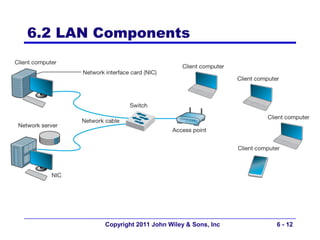
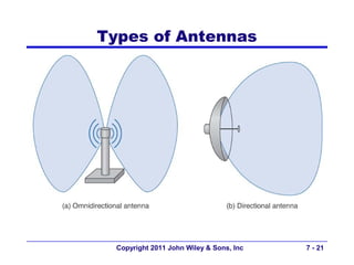
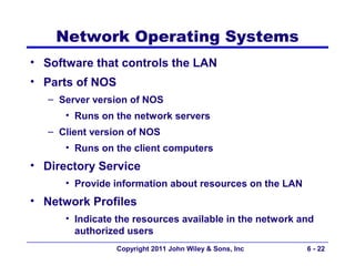
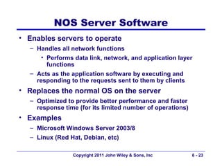
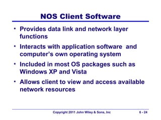
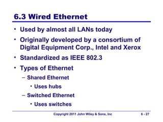
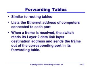
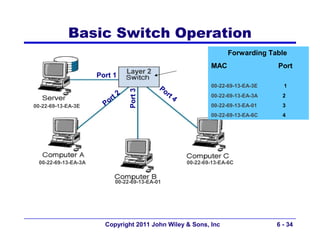
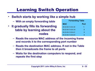
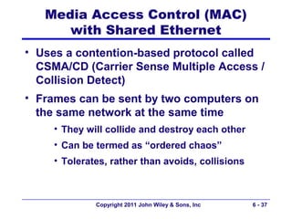
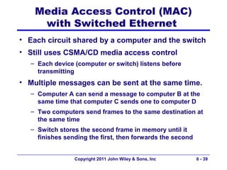
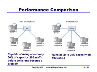
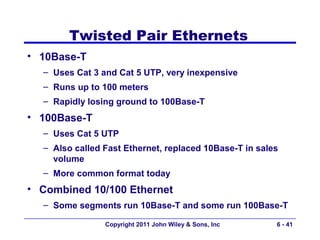
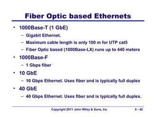
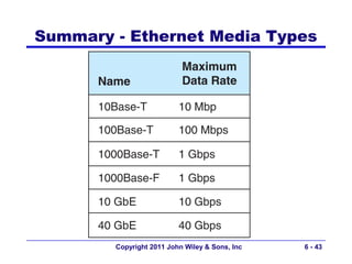
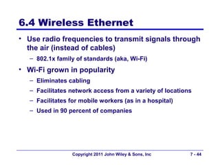
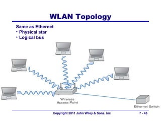
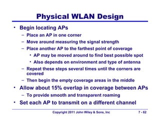
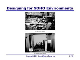
Fundamentals of Business Data
      Communications
                11th Edition

Alan Dennis & Alexandra Durcikova

         John Wiley & Sons, Inc


         Dwayne Whitten, D.B.A
         Mays Business School
         Texas A&M University
          Copyright 2011 John Wiley & Sons, Inc   6-1
Chapter 6

 Wired and Wireless
Local Area Networks


     Copyright 2011 John Wiley & Sons, Inc   6-2
Chapter 6: Outline
6.1 - Introduction
6.2 - LAN Components
6.3 - Wired Ethernet
6.4 - Wireless Ethernet
6.5 - Best Practice LAN design
6.6 - Improving LAN Performance
6.7 - Implications for Management


             Copyright 2011 John Wiley & Sons, Inc   6-3
6.1 Introduction


          Copyright 2011 John Wiley & Sons, Inc   6-4
Why Use a LAN?
• Information sharing
  – Having users access the same files, exchange
    information via email, or use Internet
     • Ex: single purchase order database accessed by all
       users on the LAN
  – Results in improved decision making
• Resource sharing
  – Having hardware devices shared by all users
     • Printers, Internet connections
  – Having software packages shared by all users on a LAN
  – Results in reduced cost

                Copyright 2011 John Wiley & Sons, Inc   6-5
Sharing Software on a LAN
• Purchase software on a per seat basis
   – Install software on a server for all to use
   – No need to have a copy on every computer on the LAN
   – Reduces cost
   – Simplifies maintenance and upgrades
   – Example
      • LAN: a 30 client network
      • Purchase only a 10-seat license for a software
        program (instead of purchasing 30 copies of the
        same program)
      • Assumes that only 10 users would simultaneously
        use the software
                  Copyright 2011 John Wiley & Sons, Inc   6-6
Sharing Software on a LAN
• LAN Metering
  – Used to control the number of copies of
    software used on a LAN
  – Available for many software packages
  – Keeps track of the users
  – Prohibits using more copies of the package
    than the licensed number
  – Helps to minimize copyright violations
     • 40% of software used in the world is illegal,
       $40B loss


              Copyright 2011 John Wiley & Sons, Inc   6-7
Dedicated Servers vs. Peer-to-Peer
• Dedicated server network
  – A server is permanently assigned a specific task
  – Most popular network type
     • 90+% of all LANs
• Peer-to-peer network
  – No dedicated servers used
  – All computers act as both clients and servers
  – Cheaper than dedicated, but less capability


              Copyright 2011 John Wiley & Sons, Inc   6-8
Dedicated Server Networks
• Requires one or more dedicated computers
  – Permanently assigned a specific task
  – Enable users to share files, printers, etc.,
  – May form a powerful enterprise network replacing
    mainframes
  – May form a server farm
  – Runs a server network operating system (NOS)
      • Windows Server 2003/8, Linux (Red Hat, CentOS)
  – Also requires a special communication software to
    enable communications with client computers


                 Copyright 2011 John Wiley & Sons, Inc   6-9
Types of Dedicated Servers
• Common Types:
  – Web servers, e-mail servers, database servers
• Others
  – File servers
     • Allows many users to share the same files on a
        common disk drive
     • Typically with restricted access
  – Print servers
     • Handle print requests
     • Could be a separate computer or a “black box”


                Copyright 2011 John Wiley & Sons, Inc   6 - 10
Peer-to-Peer Networks
• More appropriate for small networks
• Advantage:
   – Lower cost
      • No dedicated server, generally the most expensive
        network component
• Disadvantage:
   – Generally slower than dedicated server networks
      • Each computer may be in use as a client and a
         server at the same time
   – Difficult to manage


                 Copyright 2011 John Wiley & Sons, Inc   6 - 11
6.2 LAN Components


        Copyright 2011 John Wiley & Sons, Inc   6 - 12
Network Interface Cards (NICs)
• Also called network cards and network adapters
• Contains physical and data link layer protocols
   – Includes a unique data link layer address (called a MAC
     address), placed in them by their manufacturer
   – Includes a socket allowing computers to be connected
     to the network
   – Organizes data into frames and then sends them out on
     the network
• Mostly built into motherboards today
• Can be plugged into the USB port


                 Copyright 2011 John Wiley & Sons, Inc   6 - 13
Network Circuits
• Used to connect a computer physically to the
  network
• Types of cables
   – Untwisted wire pairs (UTP) – leading LAN cable type
   – Shielded twisted pair (STP)
   – Optical fiber – high capacity, just beginning in LANs


                 Copyright 2011 John Wiley & Sons, Inc       6 - 14
Hubs & Switches
Functions:
1)Act as junction boxes, linking cables from several
computers on a network
  1) Usually sold with
     4, 8, 16 or 24 ports
  2) May allow connection of more than one kind
     of cabling, such as UTP and coax.
2)Repeat (reconstruct and strengthen) incoming
signals
  –   Important since all signals become weaker with
      distance
  –   Extends the maximum LAN segment distance
                 Copyright 2011 John Wiley & Sons, Inc   6 - 15
Hubs & Switches


 Copyright 2011 John Wiley & Sons, Inc   6 - 16
Access Points
• APs are used instead of hubs/switches in
  a wireless environment
• Act as a repeater
  – They must be able to hear all computers on a
    WLAN


             Copyright 2011 John Wiley & Sons, Inc   6 - 17
Access Points


Copyright 2011 John Wiley & Sons, Inc   6 - 18
Access Points
• Power over Ethernet (POE)
  – Used to supply power to some APs
  – No external power is needed
  – Power flows over unused Cat5 wires


             Copyright 2011 John Wiley & Sons, Inc   6 - 19
Antennas used in WLANs
•   Omni directional antennas
    – Transmit in all directions simultaneously
    – Used on most WLANs
        • Dipole antenna (rubber duck)
            – Transmits in all direction (vertical, horizontal, up, down)
•   Directional antennas
    – Project signal only in one direction
       • Focused area; stronger signal; farther ranges
    – Most often used on inside of an exterior wall
       • To reduce the security issue
            – A potential problem with WLANs
    – Antennas can be made from Pringles, etc. cans and are
      called “Cantennas” (www.cantenna.com)

                     Copyright 2011 John Wiley & Sons, Inc                  7 - 20
Types of Antennas


  Copyright 2011 John Wiley & Sons, Inc   7 - 21
Network Operating Systems
• Software that controls the LAN
• Parts of NOS
   – Server version of NOS
      • Runs on the network servers
   – Client version of NOS
      • Runs on the client computers
• Directory Service
      • Provide information about resources on the LAN
• Network Profiles
      • Indicate the resources available in the network and
        authorized users
                 Copyright 2011 John Wiley & Sons, Inc   6 - 22
NOS Server Software
• Enables servers to operate
   – Handles all network functions
       • Performs data link, network, and application layer
         functions
   – Acts as the application software by executing and
     responding to the requests sent to them by clients
• Replaces the normal OS on the server
   – Optimized to provide better performance and faster
     response time (for its limited number of operations)
• Examples
   – Microsoft Windows Server 2003/8
   – Linux (Red Hat, Debian, etc)

                 Copyright 2011 John Wiley & Sons, Inc      6 - 23
NOS Client Software
• Provides data link and network layer
  functions
• Interacts with application software and
  computer’s own operating system
• Included in most OS packages such as
  Windows XP and Vista
• Allows client to view and access available
  network resources


             Copyright 2011 John Wiley & Sons, Inc   6 - 24
NOS Directory Service
• Provides information about resources on the LAN
• Example is Active Directory Service (ADS) by
  Microsoft
  – ADS servers, or domain servers, act as Domain Name
    Server (DNS)
     • Resources organized into a tree, each branch contains
       a domain (a group of resources)
         – A domain has a server (domain controller)
             » Responsible for resolving address information
               (textual name of resource  network address)
             » Responsible for managing authorization
     • A tree can be linked to other trees creating “forest”
  – Uses Lightweight Directory Service Protocol (LDAP) to
    interact with client computers

                Copyright 2011 John Wiley & Sons, Inc          6 - 25
Profiles
• Network Profiles
   – Kept by servers
   – Specify resources available for use by other computers
      • Include data files, printers, etc.
   – Configured when the LAN is established, and updated
• User profiles
   – One profile for each user, used for security reasons
   – Describe what each user on a LAN has access to
   – Includes access codes assigned to devices and users
      • Only the user with a correct code can use a specific
        device

                  Copyright 2011 John Wiley & Sons, Inc     6 - 26
6.3 Wired Ethernet
• Used by almost all LANs today
• Originally developed by a consortium of
  Digital Equipment Corp., Intel and Xerox
• Standardized as IEEE 802.3
• Types of Ethernet
  – Shared Ethernet
     • Uses hubs
  – Switched Ethernet
     • Uses switches
             Copyright 2011 John Wiley & Sons, Inc   6 - 27
Topology
• Basic geometric layout of the network
  – The way computers on the network
    interconnected
• Logical Topology
  – How the network works conceptually
  – Like a logical data flow diagram (DFD) or
  – Like a logical entity relation diagram (ERD)
• Physical Topology
  – How the network is physically installed
  – Like physical DFD or physical ERD
              Copyright 2011 John Wiley & Sons, Inc   6 - 28
Shared Ethernet’s Logical Topology
• Viewed logically as a bus topology
• All messages from any computer flow onto the
  central cable (bus)
• A computer receive messages from all other
  computers, whether the message is intended for it
  or not
• When a frame is received by a computer, the first
  task is to read the frame’s destination address to
  see if the message is meant for it or not


               Copyright 2011 John Wiley & Sons, Inc   6 - 29
Shared Ethernet’s Physical Topology


          Copyright 2011 John Wiley & Sons, Inc   6 - 30
Multiple Hub Ethernet Design


       Copyright 2011 John Wiley & Sons, Inc   6 - 31
Switched Ethernet Topology
• Uses workgroup switches
   – Designed to support a small set
     of computers (16 to 24) in one LAN
   – Looks similar to a hub, but very different inside
   – Designed to support a group of point-to-point circuits
      • No sharing of circuits
• Logical and physical topology of the network
  becomes a star topology via switch
• Switch reads destination address of the frame
  and only sends it to the corresponding port
   – While a hub broadcasts frames to all ports

                  Copyright 2011 John Wiley & Sons, Inc   6 - 32
Forwarding Tables
• Similar to routing tables
• Lists the Ethernet address of computers
  connected to each port
• When a frame is received, the switch
  reads its Layer 2 data link layer
  destination address and sends the frame
  out of the corresponding port in its
  forwarding table.


             Copyright 2011 John Wiley & Sons, Inc   6 - 33
Basic Switch Operation
                                                                  Forwarding Table
                                                            MAC                 Port
                                Layer 2
                     Port 1
                                          Po                00-22-69-13-EA-3E     1


                                Port 3
                            2                rt
                         rt                     4           00-22-69-13-EA-3A     2
00-22-69-13-EA-3E      Po                                   00-22-69-13-EA-01     3
                                                            00-22-69-13-EA-6C     4


 00-22-69-13-EA-3A                                  00-22-69-13-EA-6C


                          00-22-69-13-EA-01


                       Copyright 2011 John Wiley & Sons, Inc                    6 - 34
Learning Switch Operation
• Switch starts by working like a simple hub
                                                           Forwarding Table
   – With an empty forwarding table
                                                   MAC                  Port
• It gradually fills its forwarding                00-22-69-13-EA-3E      1

     table by learning about the                   00-22-69-13-EA-3A      2
                                                   00-22-69-13-EA-01      3
                        nodes                      00-22-69-13-EA-6C      4

   – Reads the source MAC address of the incoming frame
     and records it to the corresponding port number
   – Reads the destination MAC address. If not in the Table
     then it broadcasts the frame to all ports
   – Waits for the destination computers to respond, and
     repeats the first step


                 Copyright 2011 John Wiley & Sons, Inc                  6 - 35
Modes of Switch Operations
1. Cut through switching
   – Reads destination address and starts transmitting without
     waiting for the entire message to be received
   – Low latency; but may waste capacity (errored messages)
   – Only on the same speed incoming and outgoing circuits
1. Store and forward switching
   – Waits until the entire frame is received, perform error control,
     and then transmit it
   – Less wasted capacity; slower network
   – Circuit speeds may be different
1. Fragment free switching
   – Reads the first 64 bytes (contains the header)
   – Performs error checking; if it is OK then begins transmitting
   – It is a compromise between previous two modes
                  Copyright 2011 John Wiley & Sons, Inc     6 - 36
Media Access Control (MAC)
      with Shared Ethernet
• Uses a contention-based protocol called
  CSMA/CD (Carrier Sense Multiple Access /
  Collision Detect)
• Frames can be sent by two computers on
  the same network at the same time
     • They will collide and destroy each other
     • Can be termed as “ordered chaos”
     • Tolerates, rather than avoids, collisions


              Copyright 2011 John Wiley & Sons, Inc   6 - 37
CSMA/CD
• Carrier Sense (CS):
   – A computer listens to the bus to determine if another
     computer is transmitting before sending anything
   – Transmit when no other computer is transmitting
• Multiple Access (MA):
   – All computers have access to the network medium
• Collision Detect (CD):
   – Declared when any signal other than its own detected
   – If a collision is detected
       • To avoid a collision, both wait a random amount of
         time and then resend message

                  Copyright 2011 John Wiley & Sons, Inc   6 - 38
Media Access Control (MAC)
     with Switched Ethernet
• Each circuit shared by a computer and the switch
• Still uses CSMA/CD media access control
   – Each device (computer or switch) listens before
     transmitting
• Multiple messages can be sent at the same time.
   – Computer A can send a message to computer B at the
     same time that computer C sends one to computer D
   – Two computers send frames to the same destination at
     the same time
   – Switch stores the second frame in memory until it
     finishes sending the first, then forwards the second


                 Copyright 2011 John Wiley & Sons, Inc      6 - 39
Performance Comparison


Capable of using about only            Runs at up to 95% capacity on
50% of capacity (10BaseT)              100Base-T
before collisions become a
problem
                  Copyright 2011 John Wiley & Sons, Inc       6 - 40
Twisted Pair Ethernets
• 10Base-T
  – Uses Cat 3 and Cat 5 UTP, very inexpensive
  – Runs up to 100 meters
  – Rapidly losing ground to 100Base-T
• 100Base-T
  – Uses Cat 5 UTP
  – Also called Fast Ethernet, replaced 10Base-T in sales
    volume
  – More common format today
• Combined 10/100 Ethernet
  – Some segments run 10Base-T and some run 100Base-T

                Copyright 2011 John Wiley & Sons, Inc   6 - 41
Fiber Optic based Ethernets
• 1000Base-T (1 GbE)
  – Gigabit Ethernet.
  – Maximum cable length is only 100 m for UTP cat5
  – Fiber Optic based (1000Base-LX) runs up to 440 meters
• 1000Base-F
  – 1 Gbps fiber
• 10 GbE
  – 10 Gbps Ethernet. Uses fiber and is typically full duplex
• 40 GbE
  – 40 Gbps Ethernet. Uses fiber and is typically full duplex.

                   Copyright 2011 John Wiley & Sons, Inc   6 - 42
Summary - Ethernet Media Types


        Copyright 2011 John Wiley & Sons, Inc   6 - 43
6.4 Wireless Ethernet
• Use radio frequencies to transmit signals through
  the air (instead of cables)
   – 802.1x family of standards (aka, Wi-Fi)
• Wi-Fi grown in popularity
   – Eliminates cabling
   – Facilitates network access from a variety of locations
   – Facilitates for mobile workers (as in a hospital)
   – Used in 90 percent of companies


                  Copyright 2011 John Wiley & Sons, Inc   7 - 44
WLAN Topology
Same as Ethernet
• Physical star
• Logical bus


               Copyright 2011 John Wiley & Sons, Inc   7 - 45
WLAN Media Access Control
• Uses CSMA/CA
  – CA  collision avoidance
  – A station waits until another station is finished
    transmitting plus an additional random period of time
    before sending anything


                Copyright 2011 John Wiley & Sons, Inc   7 - 46
Association with an AP
• Scanning- searching for available Aps
• Two types
  – Active
     • NIC transmits probe frame on all active
       channels
     • AP responds with info to associate with it
  – Passive
     • NIC listens on all channel for beacon frame
     • NIC can use info in beacon frame to
       associate with AP
              Copyright 2011 John Wiley & Sons, Inc   6 - 47
MAC Techniques
• May use two MAC techniques simultaneously
  – Distributed Coordination Function (DCF)
     • Also called “Physical Carrier Sense Method”
  – Point Coordination Function (PCF)
     • Also called “Virtual Carrier Sense Method”
     • Optional: (can be set as “always”, “never”, or “just
       for certain frame sizes”)


                Copyright 2011 John Wiley & Sons, Inc    6 - 48
Distributed Coordination Function
• Relies on the ability of computers to physically
  listen before they transmit
   – When a node wants to send a message:
      • First listens to make sure that the transmitting node
        has finished, then
      • Waits a period of time longer
• Each frame is sent using stop-and-wait ARQ
   – By waiting, the listening node can detect that the
     sending node has finished and
   – Can then begin sending its transmission
   – ACK/NAK sent a short time after a frame is received,
   – Message frames are sent a somewhat longer time after
     (ensuring that no collision will occur)
                 Copyright 2011 John Wiley & Sons, Inc    7 - 49
Point Coordination Function
• Solves Hidden Node problem
  – Two computers can not detect each other’s signals
     • A computer is near the transmission limits of the AP
       at one end and another computer is near the
       transmission limits at the other end of the AP’s
       range
  – Physical carrier sense method will not work
• Solution
  – First send a Request To Send (RTS) signal to the AP
     • Request to reserve the circuit and duration
  – AP responds with a Clear To Send (CTS) signal,
     • Also indicates duration that the channel is reserved
  – Computer wishing to send begins transmitting
                Copyright 2011 John Wiley & Sons, Inc     7 - 50
Wireless Ethernet Frame Layout
• Add Figure 6.7
• Two major differences between 802.3 and
  802.11
  – .11 frame has 4 address fields
  – .11 has new field for sequence control
     • Indicates how large frame is fragmented
        – Wired networks – segmentation at transport layer
        – Wireless- at data link layer


               Copyright 2011 John Wiley & Sons, Inc   6 - 51
WLAN Characteristics
• Two frequency ranges
  – 2.4 GHz
  – 5 GHz
• Distance range of 100-150 meters
• Channels are used to reduce interference


              Copyright 2011 John Wiley & Sons, Inc   6 - 52
Types of Wireless Ethernet
          Channels        Max                 Max range
                          bandwidth
802.11a   8               54 Mbps             50 meters    Legacy
802.11b   3               11 Mbps             150 meters   Legacy
802.11g   3               54 Mbps             150 meters   Legacy
          3 -or-          200 Mbps -or-                    Latest
802.11n   1               600 Mbps            150 meters   version


                   Copyright 2011 John Wiley & Sons, Inc             6 - 53
IEEE 802.11n
• Backward compatible with a, b, and g
• Disadvantage: one laptop using a, b, or g
  slows down access by all other laptops
  (even when they are using n)


             Copyright 2011 John Wiley & Sons, Inc   7 - 54
WLAN Security
• Especially important for wireless network
  – Anyone within the range can use the WLAN
• Finding a WLAN
  – Move around with WLAN equipped device and
    try to pick up the signal
  – Use special purpose software tools to learn
    about WLAN you discovered
     • Wardriving – this type reconnaissance
     • Warchalking – writing symbols on walls to
       indicate presence of an unsecure WLAN
              Copyright 2011 John Wiley & Sons, Inc   7 - 55
Types of WLAN Security
• Service Set Identifier (SSID)
   – Required by all clients to include this in every packet
   – Included as plain text Easy to break
• Wired Equivalent Privacy (WEP)
   – Requires that user enter a key manually (to NIC and AP)
   – Communications encrypted using this key
   – Short key (40-128 bits)  Easy to break by “brute force”
• Extensible Authentication Protocol (EAP)
   – One time WEP keys created dynamically after login
   – Requires a login (with password) to a server


                  Copyright 2011 John Wiley & Sons, Inc        7 - 56
Types of WLAN Security, cont’d
• Wi-Fi Protected Access (WPA)
  – new standard
  – longer key, changed for every packet
• 802.11i (WPA2)
  – EAP login used to get session key
  – uses AES encryption
• MAC address filtering
  – Allows computers to connect to AP only if
    their MAC address is entered in the “accepted”
    list


             Copyright 2011 John Wiley & Sons, Inc   7 - 57
6.5 The Best Practice LAN Design
• Recently costs have dropped while
  speeds have increased
• WI-FI rates approaching that of wired
• WI-FI cheaper b/c of no wires to install
  – $150-400 per wire in retrofitted building
  – $50-$100 per wire in new building
• Best practice today: Wired Ethernet for
  primary LAN and WI-FI as overlay


              Copyright 2011 John Wiley & Sons, Inc   6 - 58
Best Practice Recommendations:
              Wired
• Switched 100Base-T over Cat5e
  – Relatively low cost and fast
• Category 5e cables
  – Costs decreasing
  – Provides room for upgrades to 100Base-T or 1000Base-T


                Copyright 2011 John Wiley & Sons, Inc   6 - 59
Best Practice Recommendations:
            Wireless
• Pick newest one, cost permitting
   – 802.11n (in 2011)
• Placement of APs should be considered


                 Copyright 2011 John Wiley & Sons, Inc   6 - 60
Physical WLAN Design
• More challenging than designing a traditional LAN
   – Use a temporary AP and laptop to evaluate placement of
     APs
   – Locations are chosen to provide coverage as well as to
     minimize potential interference
• Begin design with a site survey, used to determine:
   – Feasibility of desired coverage
      • Measuring the signal strength from temporary APs
   – Potential sources of interference
      • Most common source: Number and type of walls
   – Locations of wired LAN and power sources
   – Estimate of number of APs required

                Copyright 2011 John Wiley & Sons, Inc   7 - 61
Physical WLAN Design
• Begin locating APs
   – Place an AP in one corner
   – Move around measuring the signal strength
   – Place another AP to the farthest point of coverage
      • AP may be moved around to find best possible spot
      • Also depends on environment and type of antenna
   – Repeat these steps several times until the corners are
     covered
   – Then begin the empty coverage areas in the middle
• Allow about 15% overlap in coverage between APs
   – To provide smooth and transparent roaming
• Set each AP to transmit on a different channel
                 Copyright 2011 John Wiley & Sons, Inc    7 - 62
Copyright 2011 John Wiley & Sons, Inc   6 - 63
Copyright 2011 John Wiley & Sons, Inc   6 - 64
Copyright 2011 John Wiley & Sons, Inc   6 - 65
Copyright 2011 John Wiley & Sons, Inc   6 - 66
Copyright 2011 John Wiley & Sons, Inc   6 - 67
Multistory WLAN Design
• Must include
  – Usual horizontal mapping, and
  – Vertical mapping to minimize interference from APs on
    different floors


                 Copyright 2011 John Wiley & Sons, Inc   7 - 68
Designing for SOHO Environments
• Small Office / Home Office
• Typically use AP, switch, and router
  – -or- cable modem and wireless router
  – -or- all could be in one device


              Copyright 2011 John Wiley & Sons, Inc   6 - 69
Designing for SOHO Environments


         Copyright 2011 John Wiley & Sons, Inc   6 - 70
6.6 Improving LAN Performance
• Throughput:
  – Used often as a measure of LAN performance
  – Total amount of user data transmitted in a given period
    of time
• To improve throughput and LAN performance,
  identify and eliminate bottlenecks
  – Bottlenecks are points in the network where congestion
    is occurring
  – Congestion is when the network or device can’t handle
    all of the demand it is experiencing


                Copyright 2011 John Wiley & Sons, Inc   6 - 71
Identifying Network Bottlenecks
• Potential places are server vs. circuit
   – Network server
   – Network circuit (especially LAN-BN connection)
   – Client’s computer (highly unlikely, unless too old)
• How to find it
   – Check the server utilization during poor performance
      • If high >60%, then the server is the bottleneck
      • If low <40%, then the network circuit is the
        bottleneck
      • If between 40% - 60%, both the server and circuits
        are the bottlenecks

                 Copyright 2011 John Wiley & Sons, Inc     6 - 72
Improving Server Performance
• Software improvements
  – Choose a faster NOS
  – Fine tune network and NOS parameters such as
     • Amount of memory used for disk cache
     • Number of simultaneously open files
     • Amount of buffer space
• Hardware improvements
  – Add a second server
  – Upgrade the server’s CPU
  – Increase its memory space
  – Add more hard disks
  – Add a second NIC to the server
               Copyright 2011 John Wiley & Sons, Inc   6 - 73
Improving Disk Drive Performance
• Especially important, since disk reads are
  the slowest task the server needs to do
• Consider Redundant Array of Inexpensive
  Disks (RAID)
  – Replacing one large drive with many small
    ones
  – Can be used to both improve performance and
    increase reliability
  – Building redundancy into the hard drives so
    drive failure does not result in any loss of data

              Copyright 2011 John Wiley & Sons, Inc   6 - 74
Improving Circuit Capacity
• Upgrade to a faster protocol
   – Means upgrading the NICs and possible cables
   – Examples:
      • Upgrading the network from 100Base-T to 1000Base-T
      • Upgrading the segment to the server from 100Base-T to
        1000Base-T
• Increase number of circuits
   – Network segmentation
      • Wired
          – Add NICs to server that connect to multiple switches
      • Wireless
          – Add more APs on different channels
                   Copyright 2011 John Wiley & Sons, Inc           6 - 75
Network Segmentation


   Copyright 2011 John Wiley & Sons, Inc   6 - 76
Reducing Network Demand
• Move files to client computers
   – Such as heavily used software packages
• Encourage balancing of wired and wireless
  network usage by users
• Move user demands to off peak times
   – Encourage users to not use the network as heavily
     during peak usage times such as early morning or after
     lunch
   – Delay some network intensive jobs to off-peak times,
     such as run heavy printing jobs at night


                 Copyright 2011 John Wiley & Sons, Inc   6 - 77
6.7 Implications for Management
• Cost of LAN equipment dropping quickly
  – Commodity market
      • Flood of vendors into the market
      • Varying quality of products
  – Hard to justify the purchase of high quality LAN
    equipment with cheap alternatives
• Wired Ethernet now a legacy technology
  – Few new products developed for it so prices increasing
  – Move towards wireless


                   Copyright 2011 John Wiley & Sons, Inc     6 - 78
Copyright 2011 John Wiley & Sons, Inc.

 All rights reserved. Reproduction or translation of
 this work beyond that permitted in section 117 of
 the 1976 United States Copyright Act without
 express permission of the copyright owner is
 unlawful. Request for further information should
 be addressed to the Permissions Department,
 John Wiley & Sons, Inc. The purchaser may make
 back-up copies for his/her own use only and not
 for distribution or resale. The Publisher assumes
 no responsibility for errors, omissions, or
 damages caused by the use of these programs or
 from the use of the information herein.

              Copyright 2011 John Wiley & Sons, Inc   6 - 79

Ch06

  • 1.
    Fundamentals of BusinessData Communications 11th Edition Alan Dennis & Alexandra Durcikova John Wiley & Sons, Inc Dwayne Whitten, D.B.A Mays Business School Texas A&M University Copyright 2011 John Wiley & Sons, Inc 6-1
  • 2.
    Chapter 6 Wiredand Wireless Local Area Networks Copyright 2011 John Wiley & Sons, Inc 6-2
  • 3.
    Chapter 6: Outline 6.1- Introduction 6.2 - LAN Components 6.3 - Wired Ethernet 6.4 - Wireless Ethernet 6.5 - Best Practice LAN design 6.6 - Improving LAN Performance 6.7 - Implications for Management Copyright 2011 John Wiley & Sons, Inc 6-3
  • 4.
    6.1 Introduction Copyright 2011 John Wiley & Sons, Inc 6-4
  • 5.
    Why Use aLAN? • Information sharing – Having users access the same files, exchange information via email, or use Internet • Ex: single purchase order database accessed by all users on the LAN – Results in improved decision making • Resource sharing – Having hardware devices shared by all users • Printers, Internet connections – Having software packages shared by all users on a LAN – Results in reduced cost Copyright 2011 John Wiley & Sons, Inc 6-5
  • 6.
    Sharing Software ona LAN • Purchase software on a per seat basis – Install software on a server for all to use – No need to have a copy on every computer on the LAN – Reduces cost – Simplifies maintenance and upgrades – Example • LAN: a 30 client network • Purchase only a 10-seat license for a software program (instead of purchasing 30 copies of the same program) • Assumes that only 10 users would simultaneously use the software Copyright 2011 John Wiley & Sons, Inc 6-6
  • 7.
    Sharing Software ona LAN • LAN Metering – Used to control the number of copies of software used on a LAN – Available for many software packages – Keeps track of the users – Prohibits using more copies of the package than the licensed number – Helps to minimize copyright violations • 40% of software used in the world is illegal, $40B loss Copyright 2011 John Wiley & Sons, Inc 6-7
  • 8.
    Dedicated Servers vs.Peer-to-Peer • Dedicated server network – A server is permanently assigned a specific task – Most popular network type • 90+% of all LANs • Peer-to-peer network – No dedicated servers used – All computers act as both clients and servers – Cheaper than dedicated, but less capability Copyright 2011 John Wiley & Sons, Inc 6-8
  • 9.
    Dedicated Server Networks •Requires one or more dedicated computers – Permanently assigned a specific task – Enable users to share files, printers, etc., – May form a powerful enterprise network replacing mainframes – May form a server farm – Runs a server network operating system (NOS) • Windows Server 2003/8, Linux (Red Hat, CentOS) – Also requires a special communication software to enable communications with client computers Copyright 2011 John Wiley & Sons, Inc 6-9
  • 10.
    Types of DedicatedServers • Common Types: – Web servers, e-mail servers, database servers • Others – File servers • Allows many users to share the same files on a common disk drive • Typically with restricted access – Print servers • Handle print requests • Could be a separate computer or a “black box” Copyright 2011 John Wiley & Sons, Inc 6 - 10
  • 11.
    Peer-to-Peer Networks • Moreappropriate for small networks • Advantage: – Lower cost • No dedicated server, generally the most expensive network component • Disadvantage: – Generally slower than dedicated server networks • Each computer may be in use as a client and a server at the same time – Difficult to manage Copyright 2011 John Wiley & Sons, Inc 6 - 11
  • 12.
    6.2 LAN Components Copyright 2011 John Wiley & Sons, Inc 6 - 12
  • 13.
    Network Interface Cards(NICs) • Also called network cards and network adapters • Contains physical and data link layer protocols – Includes a unique data link layer address (called a MAC address), placed in them by their manufacturer – Includes a socket allowing computers to be connected to the network – Organizes data into frames and then sends them out on the network • Mostly built into motherboards today • Can be plugged into the USB port Copyright 2011 John Wiley & Sons, Inc 6 - 13
  • 14.
    Network Circuits • Usedto connect a computer physically to the network • Types of cables – Untwisted wire pairs (UTP) – leading LAN cable type – Shielded twisted pair (STP) – Optical fiber – high capacity, just beginning in LANs Copyright 2011 John Wiley & Sons, Inc 6 - 14
  • 15.
    Hubs & Switches Functions: 1)Actas junction boxes, linking cables from several computers on a network 1) Usually sold with 4, 8, 16 or 24 ports 2) May allow connection of more than one kind of cabling, such as UTP and coax. 2)Repeat (reconstruct and strengthen) incoming signals – Important since all signals become weaker with distance – Extends the maximum LAN segment distance Copyright 2011 John Wiley & Sons, Inc 6 - 15
  • 16.
    Hubs & Switches Copyright 2011 John Wiley & Sons, Inc 6 - 16
  • 17.
    Access Points • APsare used instead of hubs/switches in a wireless environment • Act as a repeater – They must be able to hear all computers on a WLAN Copyright 2011 John Wiley & Sons, Inc 6 - 17
  • 18.
    Access Points Copyright 2011John Wiley & Sons, Inc 6 - 18
  • 19.
    Access Points • Powerover Ethernet (POE) – Used to supply power to some APs – No external power is needed – Power flows over unused Cat5 wires Copyright 2011 John Wiley & Sons, Inc 6 - 19
  • 20.
    Antennas used inWLANs • Omni directional antennas – Transmit in all directions simultaneously – Used on most WLANs • Dipole antenna (rubber duck) – Transmits in all direction (vertical, horizontal, up, down) • Directional antennas – Project signal only in one direction • Focused area; stronger signal; farther ranges – Most often used on inside of an exterior wall • To reduce the security issue – A potential problem with WLANs – Antennas can be made from Pringles, etc. cans and are called “Cantennas” (www.cantenna.com) Copyright 2011 John Wiley & Sons, Inc 7 - 20
  • 21.
    Types of Antennas Copyright 2011 John Wiley & Sons, Inc 7 - 21
  • 22.
    Network Operating Systems •Software that controls the LAN • Parts of NOS – Server version of NOS • Runs on the network servers – Client version of NOS • Runs on the client computers • Directory Service • Provide information about resources on the LAN • Network Profiles • Indicate the resources available in the network and authorized users Copyright 2011 John Wiley & Sons, Inc 6 - 22
  • 23.
    NOS Server Software •Enables servers to operate – Handles all network functions • Performs data link, network, and application layer functions – Acts as the application software by executing and responding to the requests sent to them by clients • Replaces the normal OS on the server – Optimized to provide better performance and faster response time (for its limited number of operations) • Examples – Microsoft Windows Server 2003/8 – Linux (Red Hat, Debian, etc) Copyright 2011 John Wiley & Sons, Inc 6 - 23
  • 24.
    NOS Client Software •Provides data link and network layer functions • Interacts with application software and computer’s own operating system • Included in most OS packages such as Windows XP and Vista • Allows client to view and access available network resources Copyright 2011 John Wiley & Sons, Inc 6 - 24
  • 25.
    NOS Directory Service •Provides information about resources on the LAN • Example is Active Directory Service (ADS) by Microsoft – ADS servers, or domain servers, act as Domain Name Server (DNS) • Resources organized into a tree, each branch contains a domain (a group of resources) – A domain has a server (domain controller) » Responsible for resolving address information (textual name of resource  network address) » Responsible for managing authorization • A tree can be linked to other trees creating “forest” – Uses Lightweight Directory Service Protocol (LDAP) to interact with client computers Copyright 2011 John Wiley & Sons, Inc 6 - 25
  • 26.
    Profiles • Network Profiles – Kept by servers – Specify resources available for use by other computers • Include data files, printers, etc. – Configured when the LAN is established, and updated • User profiles – One profile for each user, used for security reasons – Describe what each user on a LAN has access to – Includes access codes assigned to devices and users • Only the user with a correct code can use a specific device Copyright 2011 John Wiley & Sons, Inc 6 - 26
  • 27.
    6.3 Wired Ethernet •Used by almost all LANs today • Originally developed by a consortium of Digital Equipment Corp., Intel and Xerox • Standardized as IEEE 802.3 • Types of Ethernet – Shared Ethernet • Uses hubs – Switched Ethernet • Uses switches Copyright 2011 John Wiley & Sons, Inc 6 - 27
  • 28.
    Topology • Basic geometriclayout of the network – The way computers on the network interconnected • Logical Topology – How the network works conceptually – Like a logical data flow diagram (DFD) or – Like a logical entity relation diagram (ERD) • Physical Topology – How the network is physically installed – Like physical DFD or physical ERD Copyright 2011 John Wiley & Sons, Inc 6 - 28
  • 29.
    Shared Ethernet’s LogicalTopology • Viewed logically as a bus topology • All messages from any computer flow onto the central cable (bus) • A computer receive messages from all other computers, whether the message is intended for it or not • When a frame is received by a computer, the first task is to read the frame’s destination address to see if the message is meant for it or not Copyright 2011 John Wiley & Sons, Inc 6 - 29
  • 30.
    Shared Ethernet’s PhysicalTopology Copyright 2011 John Wiley & Sons, Inc 6 - 30
  • 31.
    Multiple Hub EthernetDesign Copyright 2011 John Wiley & Sons, Inc 6 - 31
  • 32.
    Switched Ethernet Topology •Uses workgroup switches – Designed to support a small set of computers (16 to 24) in one LAN – Looks similar to a hub, but very different inside – Designed to support a group of point-to-point circuits • No sharing of circuits • Logical and physical topology of the network becomes a star topology via switch • Switch reads destination address of the frame and only sends it to the corresponding port – While a hub broadcasts frames to all ports Copyright 2011 John Wiley & Sons, Inc 6 - 32
  • 33.
    Forwarding Tables • Similarto routing tables • Lists the Ethernet address of computers connected to each port • When a frame is received, the switch reads its Layer 2 data link layer destination address and sends the frame out of the corresponding port in its forwarding table. Copyright 2011 John Wiley & Sons, Inc 6 - 33
  • 34.
    Basic Switch Operation Forwarding Table MAC Port Layer 2 Port 1 Po 00-22-69-13-EA-3E 1 Port 3 2 rt rt 4 00-22-69-13-EA-3A 2 00-22-69-13-EA-3E Po 00-22-69-13-EA-01 3 00-22-69-13-EA-6C 4 00-22-69-13-EA-3A 00-22-69-13-EA-6C 00-22-69-13-EA-01 Copyright 2011 John Wiley & Sons, Inc 6 - 34
  • 35.
    Learning Switch Operation •Switch starts by working like a simple hub Forwarding Table – With an empty forwarding table MAC Port • It gradually fills its forwarding 00-22-69-13-EA-3E 1 table by learning about the 00-22-69-13-EA-3A 2 00-22-69-13-EA-01 3 nodes 00-22-69-13-EA-6C 4 – Reads the source MAC address of the incoming frame and records it to the corresponding port number – Reads the destination MAC address. If not in the Table then it broadcasts the frame to all ports – Waits for the destination computers to respond, and repeats the first step Copyright 2011 John Wiley & Sons, Inc 6 - 35
  • 36.
    Modes of SwitchOperations 1. Cut through switching – Reads destination address and starts transmitting without waiting for the entire message to be received – Low latency; but may waste capacity (errored messages) – Only on the same speed incoming and outgoing circuits 1. Store and forward switching – Waits until the entire frame is received, perform error control, and then transmit it – Less wasted capacity; slower network – Circuit speeds may be different 1. Fragment free switching – Reads the first 64 bytes (contains the header) – Performs error checking; if it is OK then begins transmitting – It is a compromise between previous two modes Copyright 2011 John Wiley & Sons, Inc 6 - 36
  • 37.
    Media Access Control(MAC) with Shared Ethernet • Uses a contention-based protocol called CSMA/CD (Carrier Sense Multiple Access / Collision Detect) • Frames can be sent by two computers on the same network at the same time • They will collide and destroy each other • Can be termed as “ordered chaos” • Tolerates, rather than avoids, collisions Copyright 2011 John Wiley & Sons, Inc 6 - 37
  • 38.
    CSMA/CD • Carrier Sense(CS): – A computer listens to the bus to determine if another computer is transmitting before sending anything – Transmit when no other computer is transmitting • Multiple Access (MA): – All computers have access to the network medium • Collision Detect (CD): – Declared when any signal other than its own detected – If a collision is detected • To avoid a collision, both wait a random amount of time and then resend message Copyright 2011 John Wiley & Sons, Inc 6 - 38
  • 39.
    Media Access Control(MAC) with Switched Ethernet • Each circuit shared by a computer and the switch • Still uses CSMA/CD media access control – Each device (computer or switch) listens before transmitting • Multiple messages can be sent at the same time. – Computer A can send a message to computer B at the same time that computer C sends one to computer D – Two computers send frames to the same destination at the same time – Switch stores the second frame in memory until it finishes sending the first, then forwards the second Copyright 2011 John Wiley & Sons, Inc 6 - 39
  • 40.
    Performance Comparison Capable ofusing about only Runs at up to 95% capacity on 50% of capacity (10BaseT) 100Base-T before collisions become a problem Copyright 2011 John Wiley & Sons, Inc 6 - 40
  • 41.
    Twisted Pair Ethernets •10Base-T – Uses Cat 3 and Cat 5 UTP, very inexpensive – Runs up to 100 meters – Rapidly losing ground to 100Base-T • 100Base-T – Uses Cat 5 UTP – Also called Fast Ethernet, replaced 10Base-T in sales volume – More common format today • Combined 10/100 Ethernet – Some segments run 10Base-T and some run 100Base-T Copyright 2011 John Wiley & Sons, Inc 6 - 41
  • 42.
    Fiber Optic basedEthernets • 1000Base-T (1 GbE) – Gigabit Ethernet. – Maximum cable length is only 100 m for UTP cat5 – Fiber Optic based (1000Base-LX) runs up to 440 meters • 1000Base-F – 1 Gbps fiber • 10 GbE – 10 Gbps Ethernet. Uses fiber and is typically full duplex • 40 GbE – 40 Gbps Ethernet. Uses fiber and is typically full duplex. Copyright 2011 John Wiley & Sons, Inc 6 - 42
  • 43.
    Summary - EthernetMedia Types Copyright 2011 John Wiley & Sons, Inc 6 - 43
  • 44.
    6.4 Wireless Ethernet •Use radio frequencies to transmit signals through the air (instead of cables) – 802.1x family of standards (aka, Wi-Fi) • Wi-Fi grown in popularity – Eliminates cabling – Facilitates network access from a variety of locations – Facilitates for mobile workers (as in a hospital) – Used in 90 percent of companies Copyright 2011 John Wiley & Sons, Inc 7 - 44
  • 45.
    WLAN Topology Same asEthernet • Physical star • Logical bus Copyright 2011 John Wiley & Sons, Inc 7 - 45
  • 46.
    WLAN Media AccessControl • Uses CSMA/CA – CA  collision avoidance – A station waits until another station is finished transmitting plus an additional random period of time before sending anything Copyright 2011 John Wiley & Sons, Inc 7 - 46
  • 47.
    Association with anAP • Scanning- searching for available Aps • Two types – Active • NIC transmits probe frame on all active channels • AP responds with info to associate with it – Passive • NIC listens on all channel for beacon frame • NIC can use info in beacon frame to associate with AP Copyright 2011 John Wiley & Sons, Inc 6 - 47
  • 48.
    MAC Techniques • Mayuse two MAC techniques simultaneously – Distributed Coordination Function (DCF) • Also called “Physical Carrier Sense Method” – Point Coordination Function (PCF) • Also called “Virtual Carrier Sense Method” • Optional: (can be set as “always”, “never”, or “just for certain frame sizes”) Copyright 2011 John Wiley & Sons, Inc 6 - 48
  • 49.
    Distributed Coordination Function •Relies on the ability of computers to physically listen before they transmit – When a node wants to send a message: • First listens to make sure that the transmitting node has finished, then • Waits a period of time longer • Each frame is sent using stop-and-wait ARQ – By waiting, the listening node can detect that the sending node has finished and – Can then begin sending its transmission – ACK/NAK sent a short time after a frame is received, – Message frames are sent a somewhat longer time after (ensuring that no collision will occur) Copyright 2011 John Wiley & Sons, Inc 7 - 49
  • 50.
    Point Coordination Function •Solves Hidden Node problem – Two computers can not detect each other’s signals • A computer is near the transmission limits of the AP at one end and another computer is near the transmission limits at the other end of the AP’s range – Physical carrier sense method will not work • Solution – First send a Request To Send (RTS) signal to the AP • Request to reserve the circuit and duration – AP responds with a Clear To Send (CTS) signal, • Also indicates duration that the channel is reserved – Computer wishing to send begins transmitting Copyright 2011 John Wiley & Sons, Inc 7 - 50
  • 51.
    Wireless Ethernet FrameLayout • Add Figure 6.7 • Two major differences between 802.3 and 802.11 – .11 frame has 4 address fields – .11 has new field for sequence control • Indicates how large frame is fragmented – Wired networks – segmentation at transport layer – Wireless- at data link layer Copyright 2011 John Wiley & Sons, Inc 6 - 51
  • 52.
    WLAN Characteristics • Twofrequency ranges – 2.4 GHz – 5 GHz • Distance range of 100-150 meters • Channels are used to reduce interference Copyright 2011 John Wiley & Sons, Inc 6 - 52
  • 53.
    Types of WirelessEthernet Channels Max Max range bandwidth 802.11a 8 54 Mbps 50 meters Legacy 802.11b 3 11 Mbps 150 meters Legacy 802.11g 3 54 Mbps 150 meters Legacy 3 -or- 200 Mbps -or- Latest 802.11n 1 600 Mbps 150 meters version Copyright 2011 John Wiley & Sons, Inc 6 - 53
  • 54.
    IEEE 802.11n • Backwardcompatible with a, b, and g • Disadvantage: one laptop using a, b, or g slows down access by all other laptops (even when they are using n) Copyright 2011 John Wiley & Sons, Inc 7 - 54
  • 55.
    WLAN Security • Especiallyimportant for wireless network – Anyone within the range can use the WLAN • Finding a WLAN – Move around with WLAN equipped device and try to pick up the signal – Use special purpose software tools to learn about WLAN you discovered • Wardriving – this type reconnaissance • Warchalking – writing symbols on walls to indicate presence of an unsecure WLAN Copyright 2011 John Wiley & Sons, Inc 7 - 55
  • 56.
    Types of WLANSecurity • Service Set Identifier (SSID) – Required by all clients to include this in every packet – Included as plain text Easy to break • Wired Equivalent Privacy (WEP) – Requires that user enter a key manually (to NIC and AP) – Communications encrypted using this key – Short key (40-128 bits)  Easy to break by “brute force” • Extensible Authentication Protocol (EAP) – One time WEP keys created dynamically after login – Requires a login (with password) to a server Copyright 2011 John Wiley & Sons, Inc 7 - 56
  • 57.
    Types of WLANSecurity, cont’d • Wi-Fi Protected Access (WPA) – new standard – longer key, changed for every packet • 802.11i (WPA2) – EAP login used to get session key – uses AES encryption • MAC address filtering – Allows computers to connect to AP only if their MAC address is entered in the “accepted” list Copyright 2011 John Wiley & Sons, Inc 7 - 57
  • 58.
    6.5 The BestPractice LAN Design • Recently costs have dropped while speeds have increased • WI-FI rates approaching that of wired • WI-FI cheaper b/c of no wires to install – $150-400 per wire in retrofitted building – $50-$100 per wire in new building • Best practice today: Wired Ethernet for primary LAN and WI-FI as overlay Copyright 2011 John Wiley & Sons, Inc 6 - 58
  • 59.
    Best Practice Recommendations: Wired • Switched 100Base-T over Cat5e – Relatively low cost and fast • Category 5e cables – Costs decreasing – Provides room for upgrades to 100Base-T or 1000Base-T Copyright 2011 John Wiley & Sons, Inc 6 - 59
  • 60.
    Best Practice Recommendations: Wireless • Pick newest one, cost permitting – 802.11n (in 2011) • Placement of APs should be considered Copyright 2011 John Wiley & Sons, Inc 6 - 60
  • 61.
    Physical WLAN Design •More challenging than designing a traditional LAN – Use a temporary AP and laptop to evaluate placement of APs – Locations are chosen to provide coverage as well as to minimize potential interference • Begin design with a site survey, used to determine: – Feasibility of desired coverage • Measuring the signal strength from temporary APs – Potential sources of interference • Most common source: Number and type of walls – Locations of wired LAN and power sources – Estimate of number of APs required Copyright 2011 John Wiley & Sons, Inc 7 - 61
  • 62.
    Physical WLAN Design •Begin locating APs – Place an AP in one corner – Move around measuring the signal strength – Place another AP to the farthest point of coverage • AP may be moved around to find best possible spot • Also depends on environment and type of antenna – Repeat these steps several times until the corners are covered – Then begin the empty coverage areas in the middle • Allow about 15% overlap in coverage between APs – To provide smooth and transparent roaming • Set each AP to transmit on a different channel Copyright 2011 John Wiley & Sons, Inc 7 - 62
  • 63.
    Copyright 2011 JohnWiley & Sons, Inc 6 - 63
  • 64.
    Copyright 2011 JohnWiley & Sons, Inc 6 - 64
  • 65.
    Copyright 2011 JohnWiley & Sons, Inc 6 - 65
  • 66.
    Copyright 2011 JohnWiley & Sons, Inc 6 - 66
  • 67.
    Copyright 2011 JohnWiley & Sons, Inc 6 - 67
  • 68.
    Multistory WLAN Design •Must include – Usual horizontal mapping, and – Vertical mapping to minimize interference from APs on different floors Copyright 2011 John Wiley & Sons, Inc 7 - 68
  • 69.
    Designing for SOHOEnvironments • Small Office / Home Office • Typically use AP, switch, and router – -or- cable modem and wireless router – -or- all could be in one device Copyright 2011 John Wiley & Sons, Inc 6 - 69
  • 70.
    Designing for SOHOEnvironments Copyright 2011 John Wiley & Sons, Inc 6 - 70
  • 71.
    6.6 Improving LANPerformance • Throughput: – Used often as a measure of LAN performance – Total amount of user data transmitted in a given period of time • To improve throughput and LAN performance, identify and eliminate bottlenecks – Bottlenecks are points in the network where congestion is occurring – Congestion is when the network or device can’t handle all of the demand it is experiencing Copyright 2011 John Wiley & Sons, Inc 6 - 71
  • 72.
    Identifying Network Bottlenecks •Potential places are server vs. circuit – Network server – Network circuit (especially LAN-BN connection) – Client’s computer (highly unlikely, unless too old) • How to find it – Check the server utilization during poor performance • If high >60%, then the server is the bottleneck • If low <40%, then the network circuit is the bottleneck • If between 40% - 60%, both the server and circuits are the bottlenecks Copyright 2011 John Wiley & Sons, Inc 6 - 72
  • 73.
    Improving Server Performance •Software improvements – Choose a faster NOS – Fine tune network and NOS parameters such as • Amount of memory used for disk cache • Number of simultaneously open files • Amount of buffer space • Hardware improvements – Add a second server – Upgrade the server’s CPU – Increase its memory space – Add more hard disks – Add a second NIC to the server Copyright 2011 John Wiley & Sons, Inc 6 - 73
  • 74.
    Improving Disk DrivePerformance • Especially important, since disk reads are the slowest task the server needs to do • Consider Redundant Array of Inexpensive Disks (RAID) – Replacing one large drive with many small ones – Can be used to both improve performance and increase reliability – Building redundancy into the hard drives so drive failure does not result in any loss of data Copyright 2011 John Wiley & Sons, Inc 6 - 74
  • 75.
    Improving Circuit Capacity •Upgrade to a faster protocol – Means upgrading the NICs and possible cables – Examples: • Upgrading the network from 100Base-T to 1000Base-T • Upgrading the segment to the server from 100Base-T to 1000Base-T • Increase number of circuits – Network segmentation • Wired – Add NICs to server that connect to multiple switches • Wireless – Add more APs on different channels Copyright 2011 John Wiley & Sons, Inc 6 - 75
  • 76.
    Network Segmentation Copyright 2011 John Wiley & Sons, Inc 6 - 76
  • 77.
    Reducing Network Demand •Move files to client computers – Such as heavily used software packages • Encourage balancing of wired and wireless network usage by users • Move user demands to off peak times – Encourage users to not use the network as heavily during peak usage times such as early morning or after lunch – Delay some network intensive jobs to off-peak times, such as run heavy printing jobs at night Copyright 2011 John Wiley & Sons, Inc 6 - 77
  • 78.
    6.7 Implications forManagement • Cost of LAN equipment dropping quickly – Commodity market • Flood of vendors into the market • Varying quality of products – Hard to justify the purchase of high quality LAN equipment with cheap alternatives • Wired Ethernet now a legacy technology – Few new products developed for it so prices increasing – Move towards wireless Copyright 2011 John Wiley & Sons, Inc 6 - 78
  • 79.
    Copyright 2011 JohnWiley & Sons, Inc. All rights reserved. Reproduction or translation of this work beyond that permitted in section 117 of the 1976 United States Copyright Act without express permission of the copyright owner is unlawful. Request for further information should be addressed to the Permissions Department, John Wiley & Sons, Inc. The purchaser may make back-up copies for his/her own use only and not for distribution or resale. The Publisher assumes no responsibility for errors, omissions, or damages caused by the use of these programs or from the use of the information herein. Copyright 2011 John Wiley & Sons, Inc 6 - 79