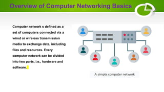
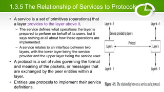
The document provides an overview of computer networking basics including definitions, elements, and concepts. It discusses:
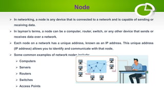
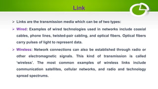
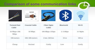
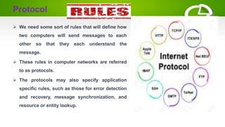
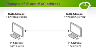
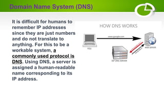
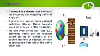
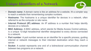
- The basic elements of computer networking including nodes, links, protocols, IP addresses, DNS, and firewalls.
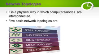
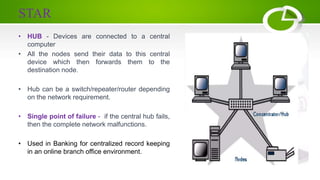
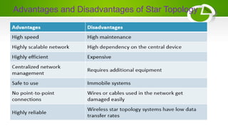
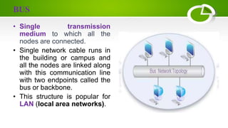
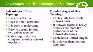
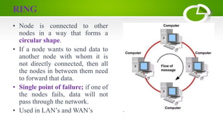
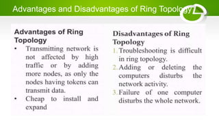
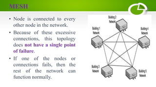
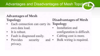
- Network topologies like star, bus, ring, mesh and their advantages/disadvantages.
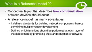
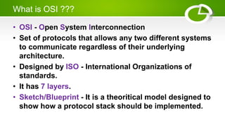
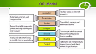
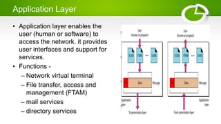
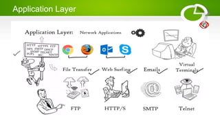
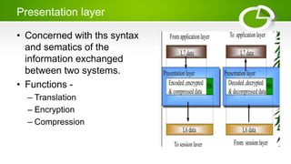
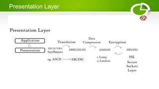
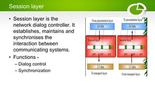
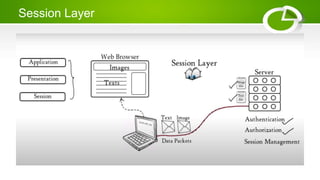
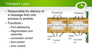
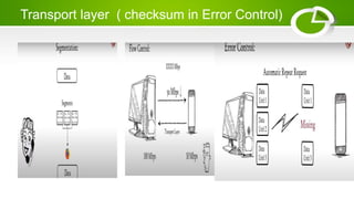
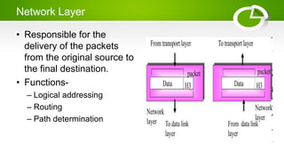
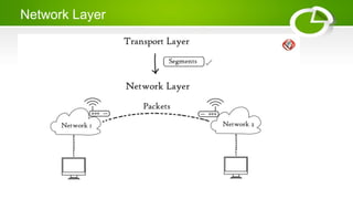
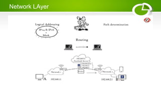
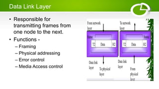
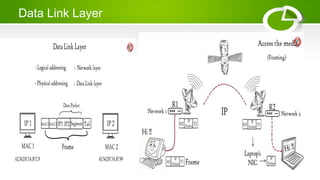
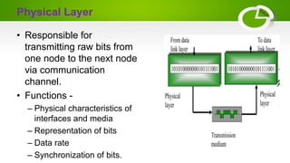
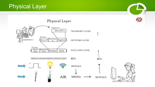
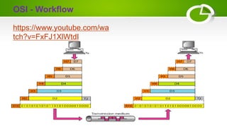
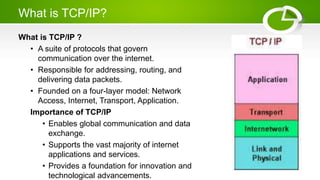
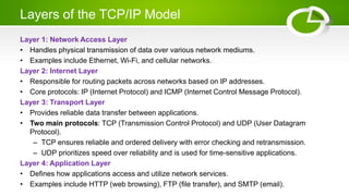
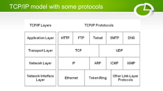
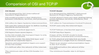
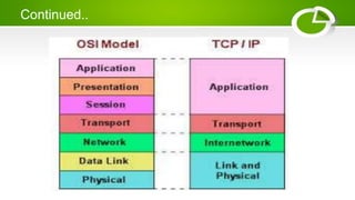
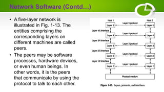
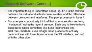
- Reference models including OSI model with its 7 layers and TCP/IP model with its 4 layers.
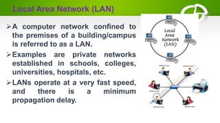
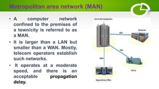
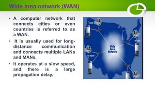
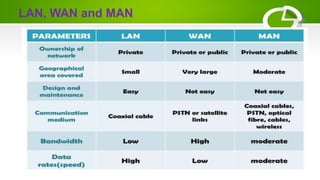
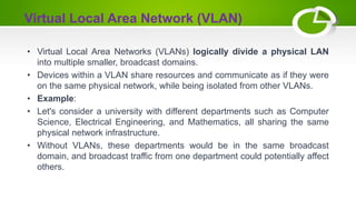
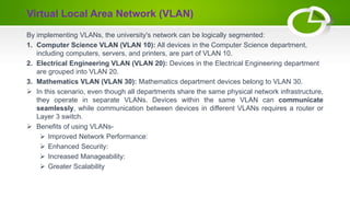
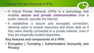
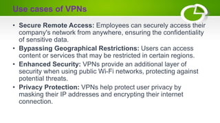
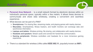
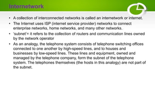
- Types of computer networks including LAN, MAN, WAN, VLAN, VPN, and PAN.
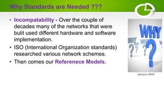
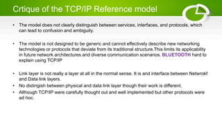
- Issues around networking standards and critiques of OSI and TCP/IP models.