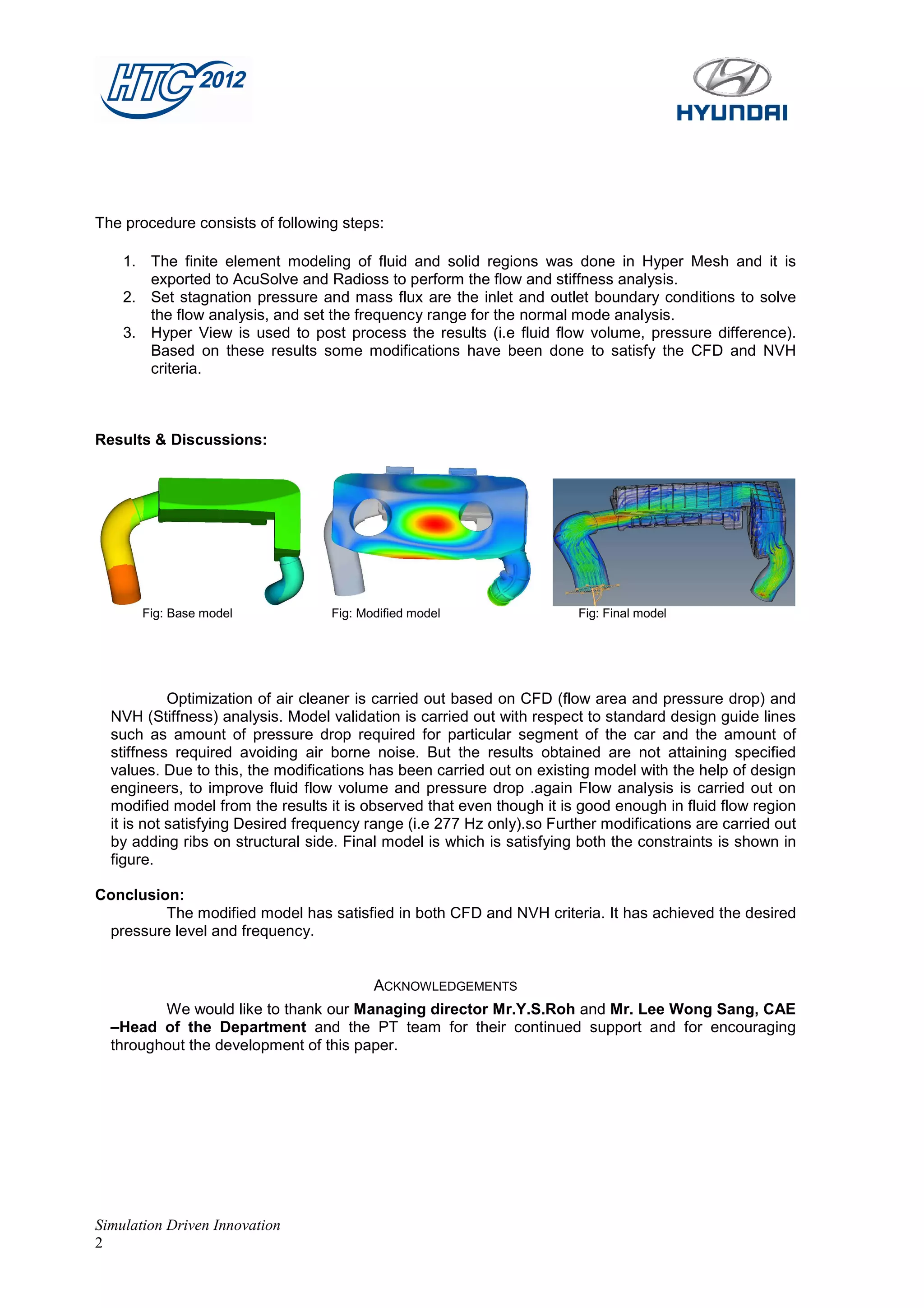
Optimization of Intake Air Cleaner
                         Srinivas Reddy Gopu                                G. Naresh Kumar
                           Deputy Manager                                 Assistant Manager
                    Hyundai Motor India Engg Pvt Ltd                Hyundai Motor India Engg Pvt Ltd
                             Hyderabad                                       Hyderabad


                                                           Abstract
              A particulate air filter is a device composed of fibrous materials which removes solid particulates such as dust,
  pollen, mold and bacteria from the air. Air filters are used in applications where air quality is important, notably in building
  ventilation systems and in engines.
              The air intakes of internal combustion engines and compressors tend to use either paper, foam or cotton filters. Oil
  bath filters have fallen out of favor. The technology of air intake filters of gas turbines has improved significantly in recent
  years, due to improvements in the aerodynamics and fluid-dynamics of the air-compressor part of the Gas Turbines. Purity
  and amount of air with the pressure is primary importance in air filter and at the same time stiffness of air cleaner is also
  much important in automobile industry. In order to achieve the specified targets we need to perform both CFD and NVH
  analysis.


Purpose:
          Flow analysis and normal mode analysis was carried out to know the pressure drop in the
  Intake air cleaner assembly and to find the frequency values. Optimize the geometry to meet the
  desired pressure levels by considering NVH characteristics like frequency and mode shapes.

The main Objectives of this analysis:
• To know the pressure difference between inlet to outlet of the air cleaner assembly.
• To check out the fluid flow volume (by identifying any unnecessary flow volume in the air cleaner).
• Results of this analysis can be used to modify the air cleaner geometry with respect to NVH
analysis.


                            Fig: Solid model                                           Fig: Fluid model


Introduction

   In this paper we are analyzing the intake air cleaner assembly with the help of CFD and NVH
  procedure and with this we will know the pressure and frequency. Finally with the help of fluid flow
  volume and pressure drop results we will modify the flow region and with frequency results we will
  modify the solid region of air cleaner.

Process Methodology:

              For all type of approaches, we have same procedure as pre-processing, solving, and
  post processing.


Simulation Driven Innovation
1
The procedure consists of following steps:

    1. The finite element modeling of fluid and solid regions was done in Hyper Mesh and it is
       exported to AcuSolve and Radioss to perform the flow and stiffness analysis.
    2. Set stagnation pressure and mass flux are the inlet and outlet boundary conditions to solve
       the flow analysis, and set the frequency range for the normal mode analysis.
    3. Hyper View is used to post process the results (i.e fluid flow volume, pressure difference).
       Based on these results some modifications have been done to satisfy the CFD and NVH
       criteria.


Results & Discussions:


       Fig: Base model             Fig: Modified model                  Fig: Final model


            Optimization of air cleaner is carried out based on CFD (flow area and pressure drop) and
  NVH (Stiffness) analysis. Model validation is carried out with respect to standard design guide lines
  such as amount of pressure drop required for particular segment of the car and the amount of
  stiffness required avoiding air borne noise. But the results obtained are not attaining specified
  values. Due to this, the modifications has been carried out on existing model with the help of design
  engineers, to improve fluid flow volume and pressure drop .again Flow analysis is carried out on
  modified model from the results it is observed that even though it is good enough in fluid flow region
  it is not satisfying Desired frequency range (i.e 277 Hz only).so Further modifications are carried out
  by adding ribs on structural side. Final model is which is satisfying both the constraints is shown in
  figure.

Conclusion:
         The modified model has satisfied in both CFD and NVH criteria. It has achieved the desired
 pressure level and frequency.


                                          ACKNOWLEDGEMENTS
         We would like to thank our Managing director Mr.Y.S.Roh and Mr. Lee Wong Sang, CAE
  –Head of the Department and the PT team for their continued support and for encouraging
  throughout the development of this paper.


Simulation Driven Innovation
2

Cfd02 optimization of-hyundai-motor

  • 1.
    Optimization of IntakeAir Cleaner Srinivas Reddy Gopu G. Naresh Kumar Deputy Manager Assistant Manager Hyundai Motor India Engg Pvt Ltd Hyundai Motor India Engg Pvt Ltd Hyderabad Hyderabad Abstract A particulate air filter is a device composed of fibrous materials which removes solid particulates such as dust, pollen, mold and bacteria from the air. Air filters are used in applications where air quality is important, notably in building ventilation systems and in engines. The air intakes of internal combustion engines and compressors tend to use either paper, foam or cotton filters. Oil bath filters have fallen out of favor. The technology of air intake filters of gas turbines has improved significantly in recent years, due to improvements in the aerodynamics and fluid-dynamics of the air-compressor part of the Gas Turbines. Purity and amount of air with the pressure is primary importance in air filter and at the same time stiffness of air cleaner is also much important in automobile industry. In order to achieve the specified targets we need to perform both CFD and NVH analysis. Purpose: Flow analysis and normal mode analysis was carried out to know the pressure drop in the Intake air cleaner assembly and to find the frequency values. Optimize the geometry to meet the desired pressure levels by considering NVH characteristics like frequency and mode shapes. The main Objectives of this analysis: • To know the pressure difference between inlet to outlet of the air cleaner assembly. • To check out the fluid flow volume (by identifying any unnecessary flow volume in the air cleaner). • Results of this analysis can be used to modify the air cleaner geometry with respect to NVH analysis. Fig: Solid model Fig: Fluid model Introduction In this paper we are analyzing the intake air cleaner assembly with the help of CFD and NVH procedure and with this we will know the pressure and frequency. Finally with the help of fluid flow volume and pressure drop results we will modify the flow region and with frequency results we will modify the solid region of air cleaner. Process Methodology: For all type of approaches, we have same procedure as pre-processing, solving, and post processing. Simulation Driven Innovation 1
  • 2.
    The procedure consistsof following steps: 1. The finite element modeling of fluid and solid regions was done in Hyper Mesh and it is exported to AcuSolve and Radioss to perform the flow and stiffness analysis. 2. Set stagnation pressure and mass flux are the inlet and outlet boundary conditions to solve the flow analysis, and set the frequency range for the normal mode analysis. 3. Hyper View is used to post process the results (i.e fluid flow volume, pressure difference). Based on these results some modifications have been done to satisfy the CFD and NVH criteria. Results & Discussions: Fig: Base model Fig: Modified model Fig: Final model Optimization of air cleaner is carried out based on CFD (flow area and pressure drop) and NVH (Stiffness) analysis. Model validation is carried out with respect to standard design guide lines such as amount of pressure drop required for particular segment of the car and the amount of stiffness required avoiding air borne noise. But the results obtained are not attaining specified values. Due to this, the modifications has been carried out on existing model with the help of design engineers, to improve fluid flow volume and pressure drop .again Flow analysis is carried out on modified model from the results it is observed that even though it is good enough in fluid flow region it is not satisfying Desired frequency range (i.e 277 Hz only).so Further modifications are carried out by adding ribs on structural side. Final model is which is satisfying both the constraints is shown in figure. Conclusion: The modified model has satisfied in both CFD and NVH criteria. It has achieved the desired pressure level and frequency. ACKNOWLEDGEMENTS We would like to thank our Managing director Mr.Y.S.Roh and Mr. Lee Wong Sang, CAE –Head of the Department and the PT team for their continued support and for encouraging throughout the development of this paper. Simulation Driven Innovation 2