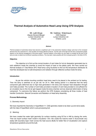
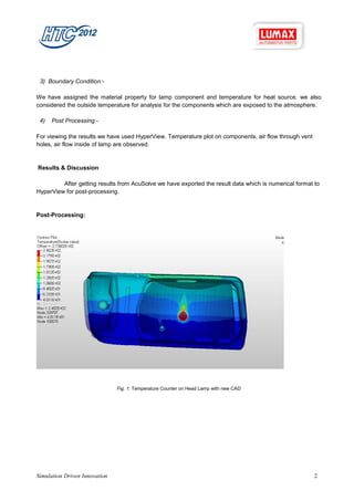
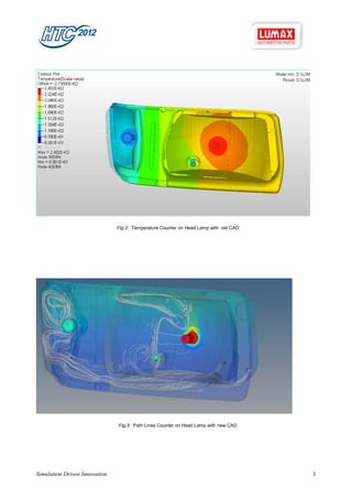
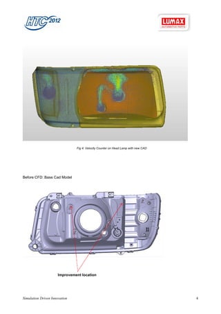
Thermal Analysis of Automotive Head Lamp Using CFD Analysis


                                   Mr. Lalit Ahuja                     Mr. Vaibhav Wakchaure
                               Deputy General Manger                           CAE Engineer
                                Lumax Industries Ltd.                       Lumax Industries Ltd.
                                   Chakan, pune                                Chakan, pune


                                                               Abstract

Thermal analysis of automotive lamps have become a significant part in the automotive industry’s design cycle due to the increased
demand from the customers for more durable and energy efficient products. The life cycle of the light and the lamp components greatly
depend on the thermal management of the lamp system. Thermal analysis of the lamps not only helps to increase the life time of the
lamp but also to determine its efficient operating conditions. This has been made possible with the increased growth in the field of CFD.


Objective

        The objective is to find out the correct location of vent holes for hot air dissipation generated due to
bulb radiations inside the chamber to avoid the impact of heat on the plastic parts. We have carried out
thermal analysis of -Tata Motors SFC Head lamp using AcuSolve to find out the temperature distribution &
heat flow developed due to bulb temperature and radiation through reflective surface inside the lamp.


Introduction

         As per the vehicle mounting condition head lamp need to be placed in the ambient air for testing.
Then the lamp is switched on as per std. for 24 hr. After testing period it is observed that the lamp
component gets deformed due to high heat generated in the lamp and improper heat dissipation through
vent holes provided. The number of vent holes provided or location of vent hole provided is not sufficient for
air circulation due to this hot air get trapped inside the lamp chamber and we observed deformation of lamp
component. To overcome this failure we perform the CFD Analysis considering all three modes of heat
transfer Conduction, Natural Convection and Radiation on head lamp Assembly.

Process Methodology

1) Geometry Import:

We have imported the Geometry in HyperMesh-11. CAD geometry needs to be clean up and done easily
with the help of HyperMesh which is pre-processing tool.

2) Meshing:

We have created the water tight geometry for surface meshing using R-Tria in HM by closing the vents.
Then we import surface mesh model in AcuSolve 1.8-b. We create the Volume mesh in AcuConsole very
easily with boundary layer mesh across the heat source (Bulb) for better flow of visualization and capture
temperature gradients around the bulb.


Simulation Driven Innovation                                                                                                         1
3) Boundary Condition:-

We have assigned the material property for lamp component and temperature for heat source. we also
considered the outside temperature for analysis for the components which are exposed to the atmosphere.

 4)   Post Processing:-

For viewing the results we have used HyperView. Temperature plot on components, air flow through vent
holes, air flow inside of lamp are observed.


Results & Discussion

         After getting results from AcuSolve we have exported the result data which is numerical format to
HyperView for post-processing.


Post-Processing:


                               Fig. 1: Temperature Counter on Head Lamp with new CAD


Simulation Driven Innovation                                                                            2
Fig.2: Temperature Counter on Head Lamp with old CAD


                               Fig.3: Path Lines Counter on Head Lamp with new CAD


Simulation Driven Innovation                                                          3
Fig 4: Velocity Counter on Head Lamp with new CAD


Before CFD: Base Cad Model


                      Improvement location


Simulation Driven Innovation                                                       4
After CFD: Optimized Cad Model


                          Improved location


As shown in above picture we made changes in the cad geometry and done the analysis. We increased the
number of vent holes and changed the location of vent holes for proper ventilation through lamp. This is
analyzed and validated for both thermal and structural vibrations.

Benefit Summary

Meshing of plastic parts is really typical. As we look into our Product – It is very complicated, specially the
Reflector and the Housing. HyperMesh helped us for meshing such complicated components with ease. for
air mesh and boundary layer mesh we use AcuSolve which is required very less time .After the Analysis we
found vent hole location is not accurate for air circulation we modify the location and also we modify the
material of component which can withstand the high temperature. Using HyperMesh along with AcuSolve
which has been successful solution for the above problem.

Challenges

Defect free launch and to overcome from Warranty issue later due to heat and field failure. To avoid Major
Material change later, if it fails. Having large reflectors in the head lamp, heat generated will be high so its
control and proper dissipation is another challenge.


Simulation Driven Innovation                                                                                 5
Future Plan

 Now in future we have introduced CFD Analysis as a part of Design Process during the Product Design
Stage. This helps us in validating the Product virtually and ensures good quality and Cost effective Product
before creating any Physical proto samples. And also to run a transient analysis to simulate the ON-OFF
condition for the lamps.

Conclusion

 As per the analysis results, we found for Hot air circulation we required more vent hole with accurate
location and also we have changed Grade of the material having the HDT value.


Simulation Driven Innovation                                                                              6

Cfd03 thermal analysis-of-automotive-lumax

  • 1.
    Thermal Analysis ofAutomotive Head Lamp Using CFD Analysis Mr. Lalit Ahuja Mr. Vaibhav Wakchaure Deputy General Manger CAE Engineer Lumax Industries Ltd. Lumax Industries Ltd. Chakan, pune Chakan, pune Abstract Thermal analysis of automotive lamps have become a significant part in the automotive industry’s design cycle due to the increased demand from the customers for more durable and energy efficient products. The life cycle of the light and the lamp components greatly depend on the thermal management of the lamp system. Thermal analysis of the lamps not only helps to increase the life time of the lamp but also to determine its efficient operating conditions. This has been made possible with the increased growth in the field of CFD. Objective The objective is to find out the correct location of vent holes for hot air dissipation generated due to bulb radiations inside the chamber to avoid the impact of heat on the plastic parts. We have carried out thermal analysis of -Tata Motors SFC Head lamp using AcuSolve to find out the temperature distribution & heat flow developed due to bulb temperature and radiation through reflective surface inside the lamp. Introduction As per the vehicle mounting condition head lamp need to be placed in the ambient air for testing. Then the lamp is switched on as per std. for 24 hr. After testing period it is observed that the lamp component gets deformed due to high heat generated in the lamp and improper heat dissipation through vent holes provided. The number of vent holes provided or location of vent hole provided is not sufficient for air circulation due to this hot air get trapped inside the lamp chamber and we observed deformation of lamp component. To overcome this failure we perform the CFD Analysis considering all three modes of heat transfer Conduction, Natural Convection and Radiation on head lamp Assembly. Process Methodology 1) Geometry Import: We have imported the Geometry in HyperMesh-11. CAD geometry needs to be clean up and done easily with the help of HyperMesh which is pre-processing tool. 2) Meshing: We have created the water tight geometry for surface meshing using R-Tria in HM by closing the vents. Then we import surface mesh model in AcuSolve 1.8-b. We create the Volume mesh in AcuConsole very easily with boundary layer mesh across the heat source (Bulb) for better flow of visualization and capture temperature gradients around the bulb. Simulation Driven Innovation 1
  • 2.
    3) Boundary Condition:- Wehave assigned the material property for lamp component and temperature for heat source. we also considered the outside temperature for analysis for the components which are exposed to the atmosphere. 4) Post Processing:- For viewing the results we have used HyperView. Temperature plot on components, air flow through vent holes, air flow inside of lamp are observed. Results & Discussion After getting results from AcuSolve we have exported the result data which is numerical format to HyperView for post-processing. Post-Processing: Fig. 1: Temperature Counter on Head Lamp with new CAD Simulation Driven Innovation 2
  • 3.
    Fig.2: Temperature Counteron Head Lamp with old CAD Fig.3: Path Lines Counter on Head Lamp with new CAD Simulation Driven Innovation 3
  • 4.
    Fig 4: VelocityCounter on Head Lamp with new CAD Before CFD: Base Cad Model Improvement location Simulation Driven Innovation 4
  • 5.
    After CFD: OptimizedCad Model Improved location As shown in above picture we made changes in the cad geometry and done the analysis. We increased the number of vent holes and changed the location of vent holes for proper ventilation through lamp. This is analyzed and validated for both thermal and structural vibrations. Benefit Summary Meshing of plastic parts is really typical. As we look into our Product – It is very complicated, specially the Reflector and the Housing. HyperMesh helped us for meshing such complicated components with ease. for air mesh and boundary layer mesh we use AcuSolve which is required very less time .After the Analysis we found vent hole location is not accurate for air circulation we modify the location and also we modify the material of component which can withstand the high temperature. Using HyperMesh along with AcuSolve which has been successful solution for the above problem. Challenges Defect free launch and to overcome from Warranty issue later due to heat and field failure. To avoid Major Material change later, if it fails. Having large reflectors in the head lamp, heat generated will be high so its control and proper dissipation is another challenge. Simulation Driven Innovation 5
  • 6.
    Future Plan Nowin future we have introduced CFD Analysis as a part of Design Process during the Product Design Stage. This helps us in validating the Product virtually and ensures good quality and Cost effective Product before creating any Physical proto samples. And also to run a transient analysis to simulate the ON-OFF condition for the lamps. Conclusion As per the analysis results, we found for Hot air circulation we required more vent hole with accurate location and also we have changed Grade of the material having the HDT value. Simulation Driven Innovation 6