Downloaded 150 times
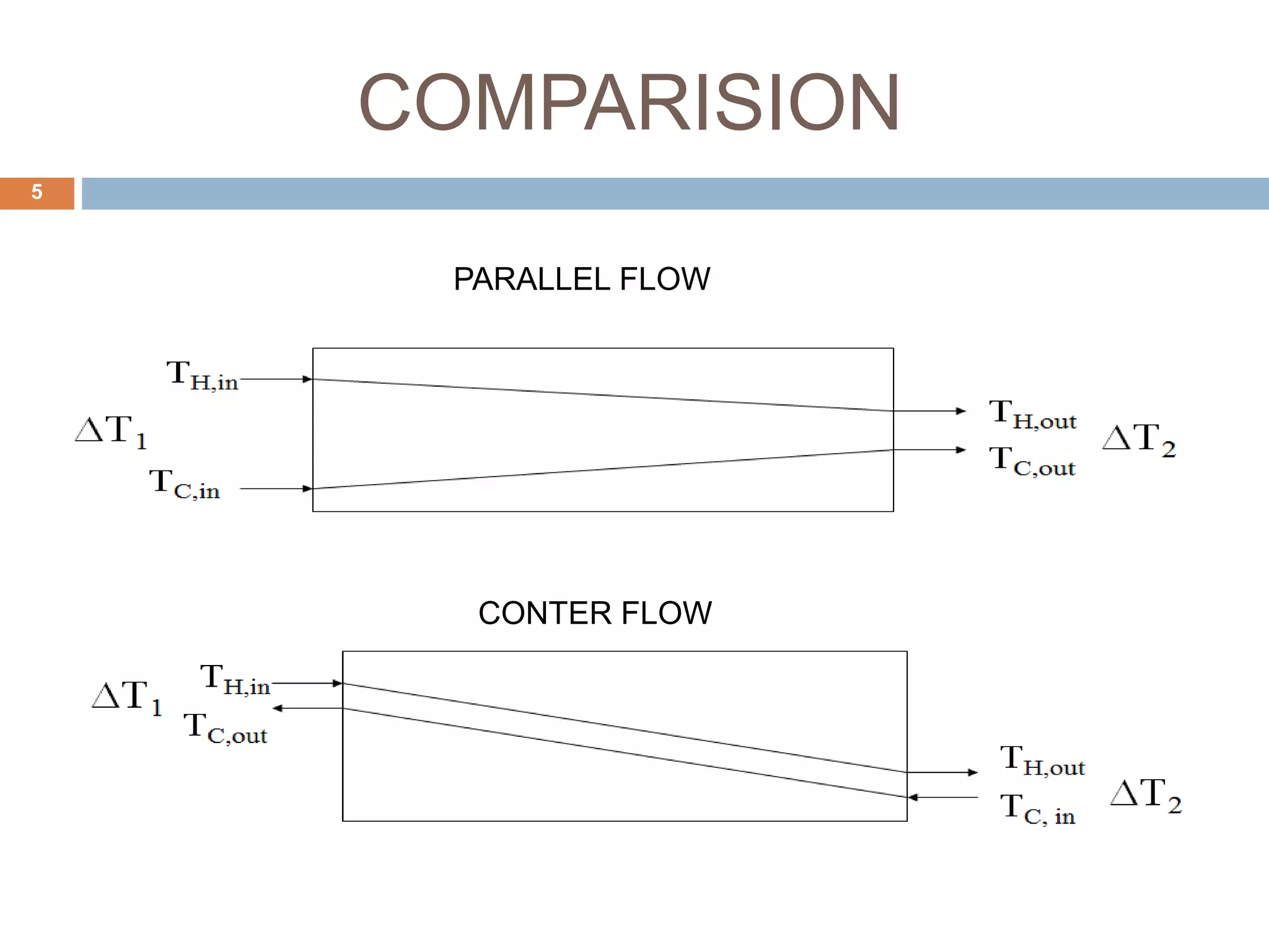
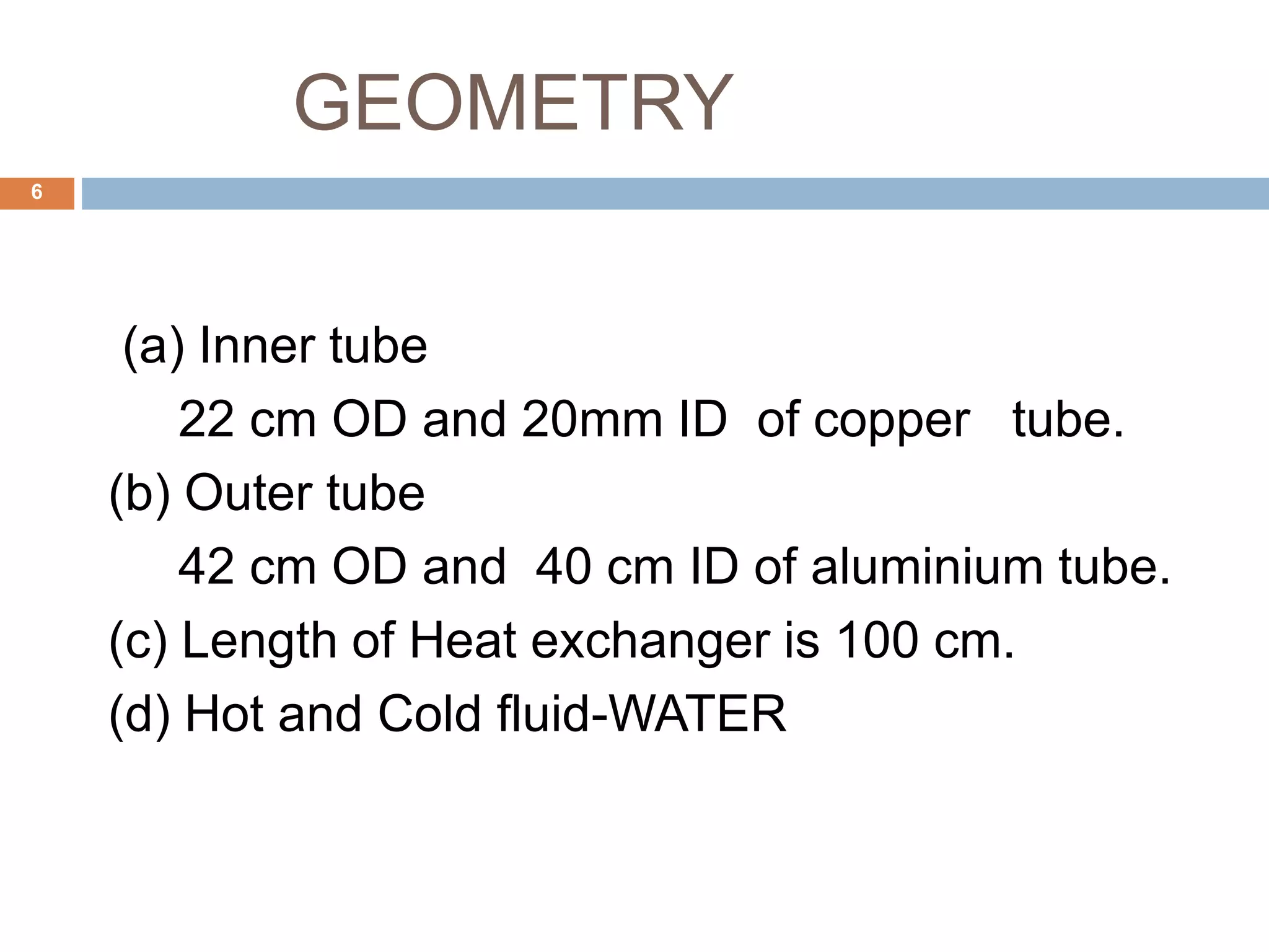
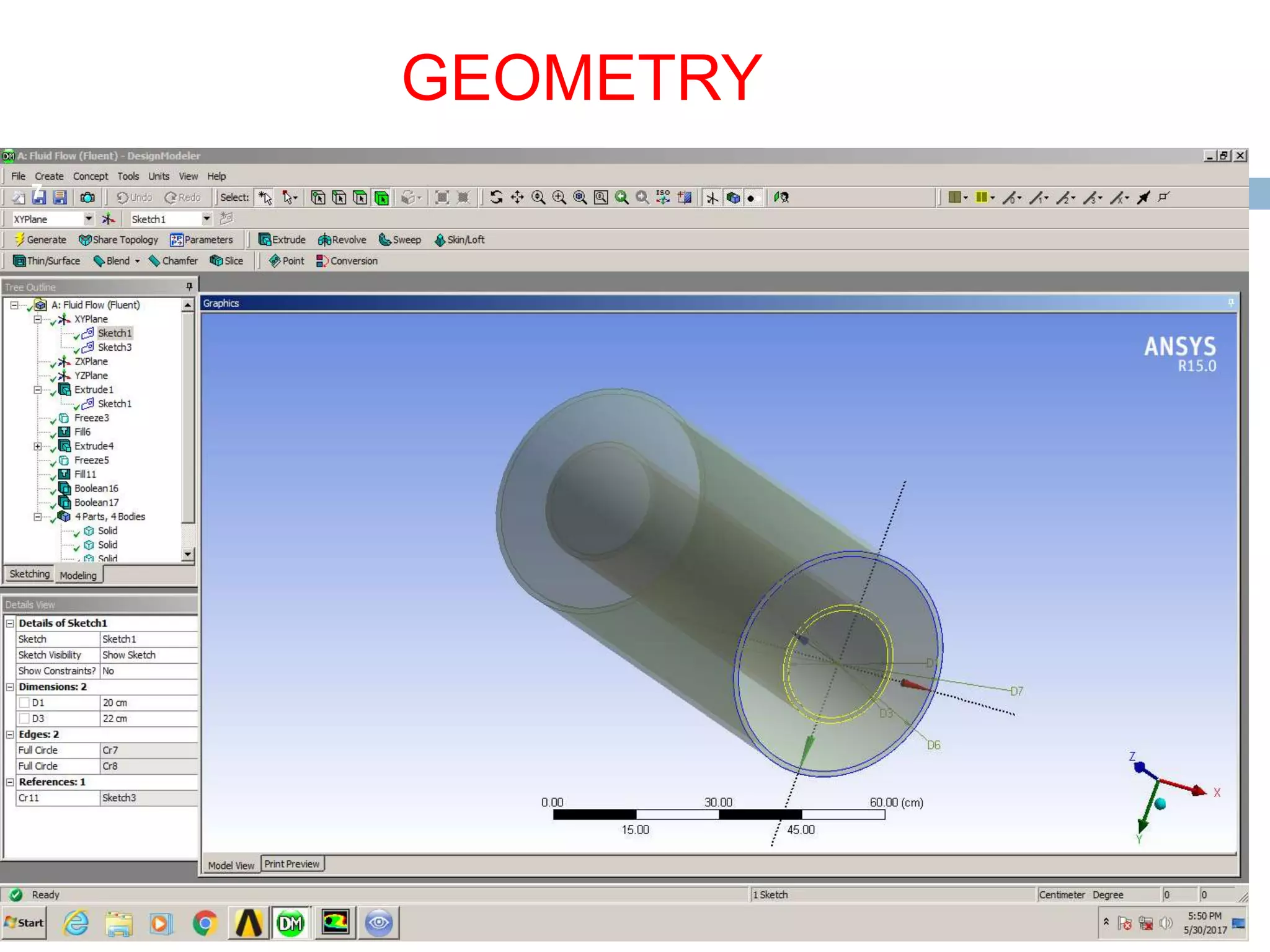
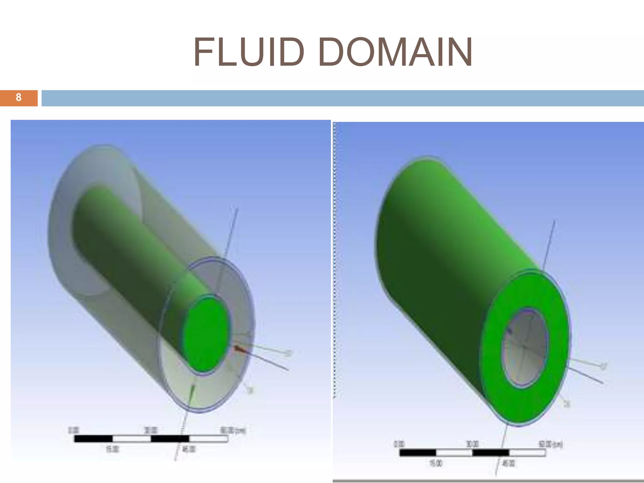
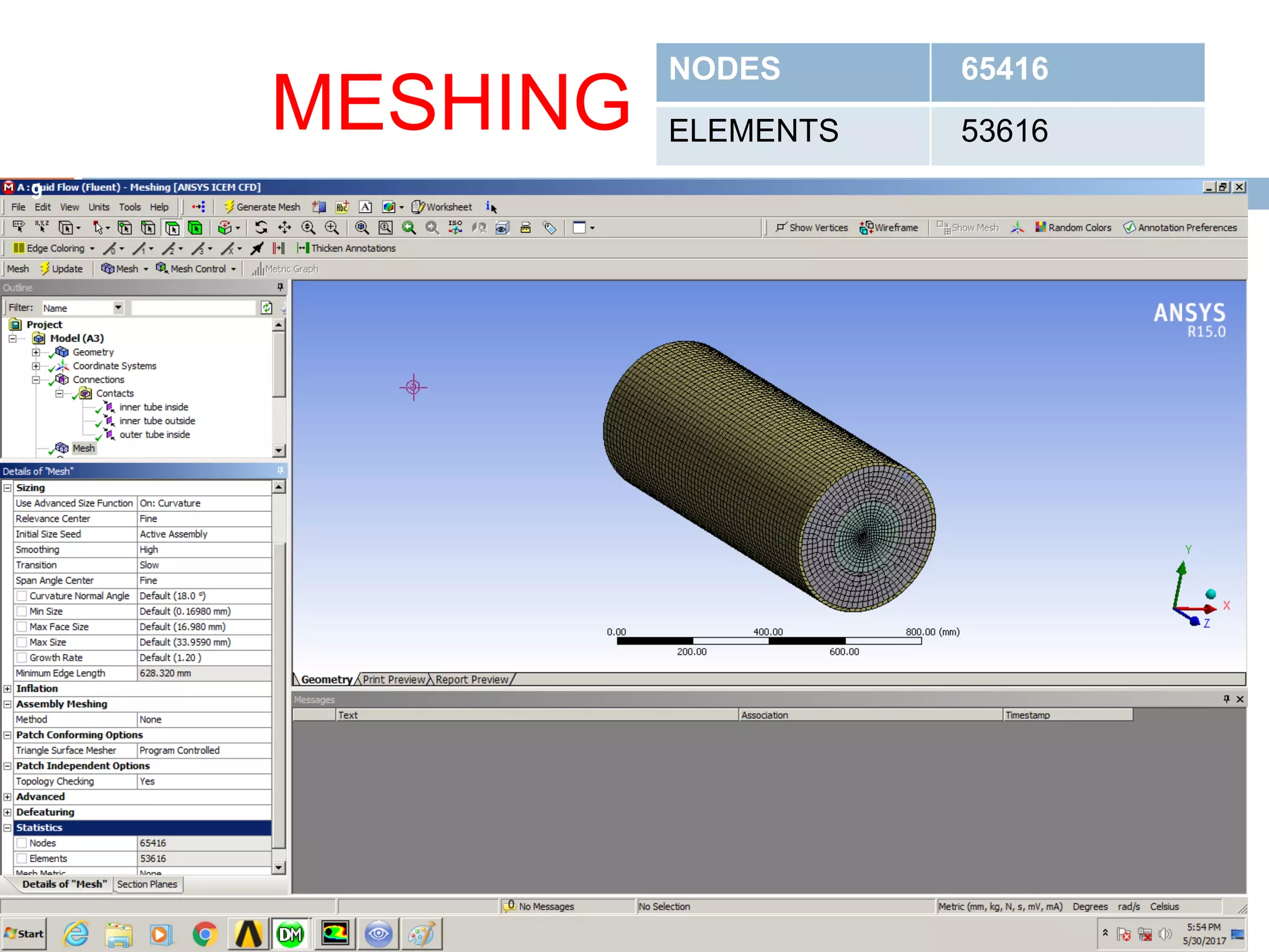
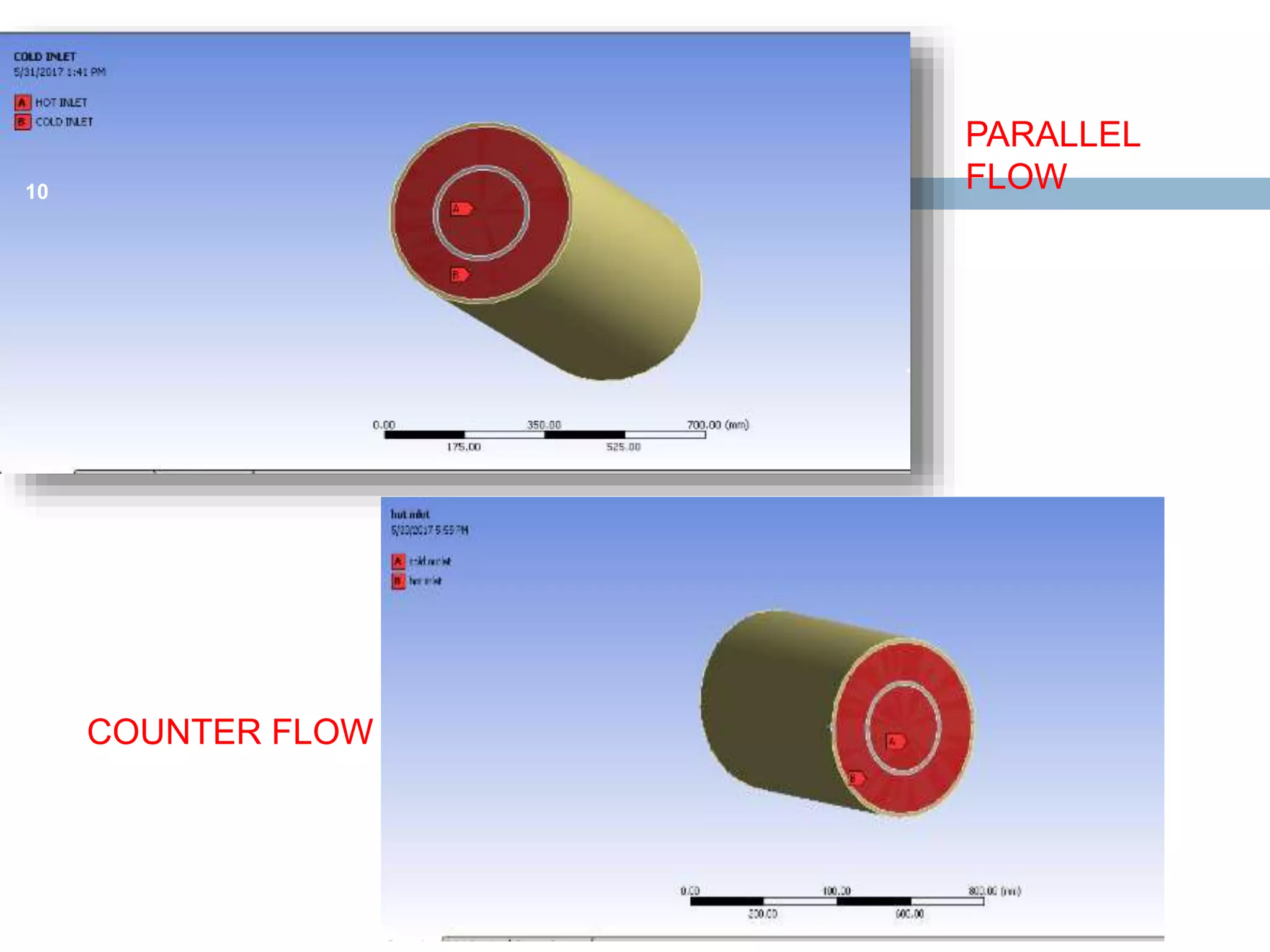
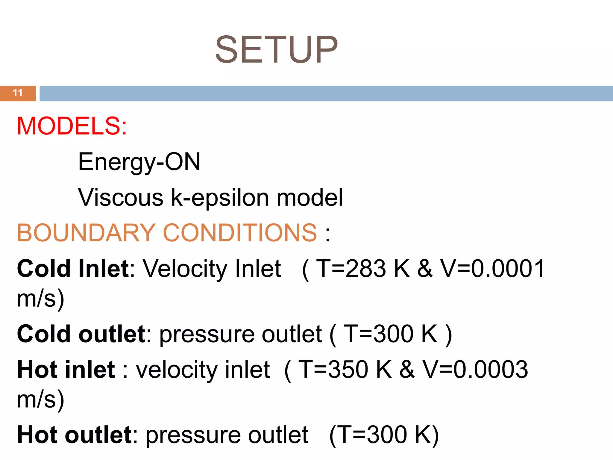
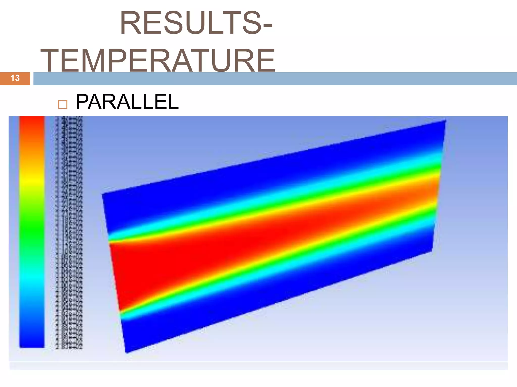
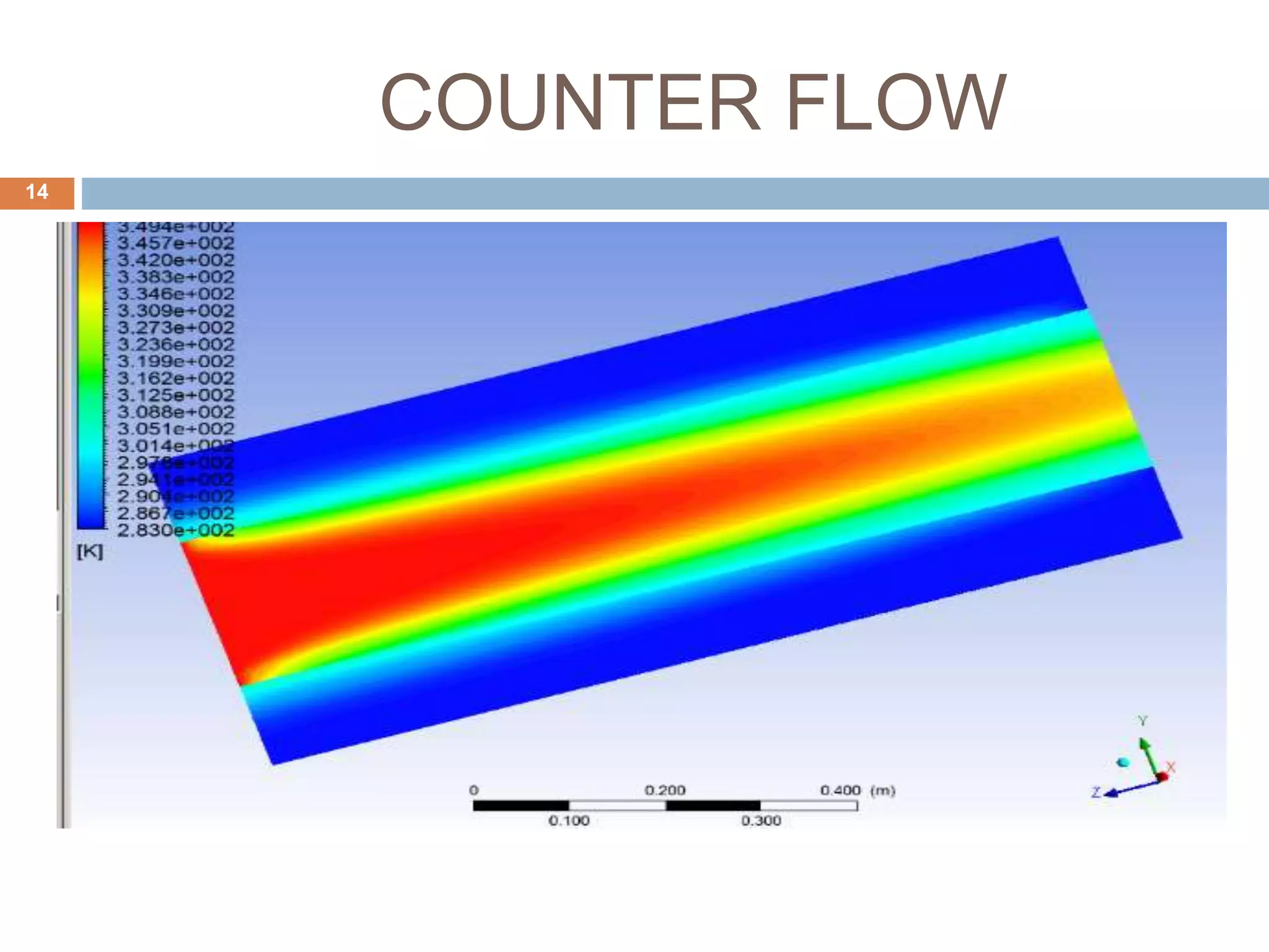
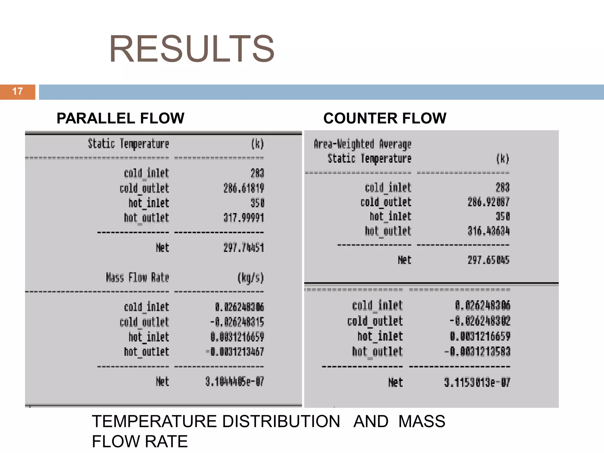
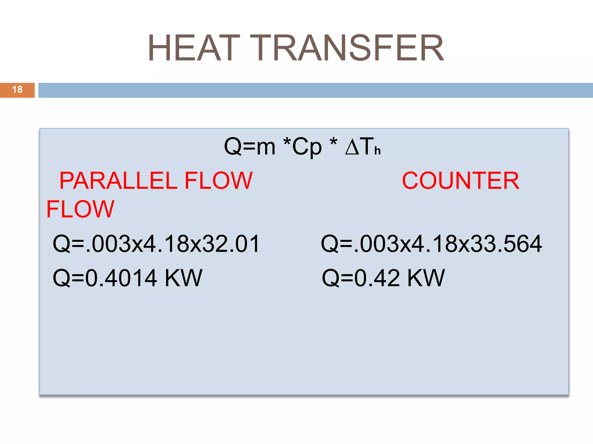

This document summarizes a CFD analysis of a double pipe heat exchanger. It describes the geometry of the heat exchanger with an inner copper tube and outer aluminum tube. It also discusses the meshing and boundary conditions used in the CFD model. The results show that counter-current flow has a more uniform temperature distribution and higher heat transfer rate compared to parallel flow. The conclusion is that counter-current flow is more effective for heat transfer in a double pipe heat exchanger.


![Heat_exchanger_1[7537].pptx](https://cdn.slidesharecdn.com/ss_thumbnails/heatexchanger17537-230514132732-295f8f89-thumbnail.jpg?width=640&height=640&fit=bounds)


