Downloaded 54 times
![Cell signal encoding
To distinguish signals from several different transmitters, frequency division multiple access(FDMA) and code
division multiple access (CDMA) were developed.
With FDMA, the transmitting and receiving frequencies used in each cell are different from the frequencies
used in each neighbouring cell. In a simple taxi system, the taxi driver manually tuned to a frequency of a
chosen cell to obtain a strong signal and to avoid interference from signals from other cells.
The principle of CDMA is more complex, but achieves the same result; the distributed transceivers can select
one cell and listen to it.
Other available methods of multiplexing such as polarization division multiple access (PDMA) and time division
multiple access (TDMA) cannot be used to separate signals from one cell to the next since the effects of both
vary with position and this would make signal separation practically impossible. Time division multiple access,
however, is used in combination with either FDMA or CDMA in a number of systems to give multiple channels
within the coverage area of a single cell.
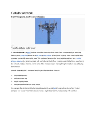
Frequency reuse
The key characteristic of a cellular network is the ability to re-use frequencies to increase both coverage and
capacity. As described above, adjacent cells must utilize different frequencies, however there is no problem
with two cells sufficiently far apart operating on the same frequency. The elements that determine frequency
reuse are the reuse distance and the reuse factor.
The reuse distance, D is calculated as
where R is the cell radius and N is the number of cells per cluster. Cells may vary in radius in the ranges
(1 km to 30 km). The boundaries of the cells can also overlap between adjacent cells and large cells can
be divided into smaller cells [1]
The frequency reuse factor is the rate at which the same frequency can be used in the network. It
is 1/K (or K according to some books) where K is the number of cells which cannot use the same
frequencies for transmission. Common values for the frequency reuse factor are 1/3, 1/4, 1/7, 1/9 and 1/12
(or 3, 4, 7, 9 and 12 depending on notation).
In case of N sector antennas on the same base station site, each with different direction, the base station
site can serve N different sectors. N is typically 3. A reuse pattern of N/K denotes a further division in
frequency among N sector antennas per site. Some current and historical reuse patterns are 3/7 (North
American AMPS), 6/4 (Motorola NAMPS), and 3/4 (GSM).](https://image.slidesharecdn.com/cellularnetwork-wikipediathefreeencyclopedia-120114185734-phpapp01/85/Cellular-network-wikipedia-the-free-encyclopedia-3-320.jpg)
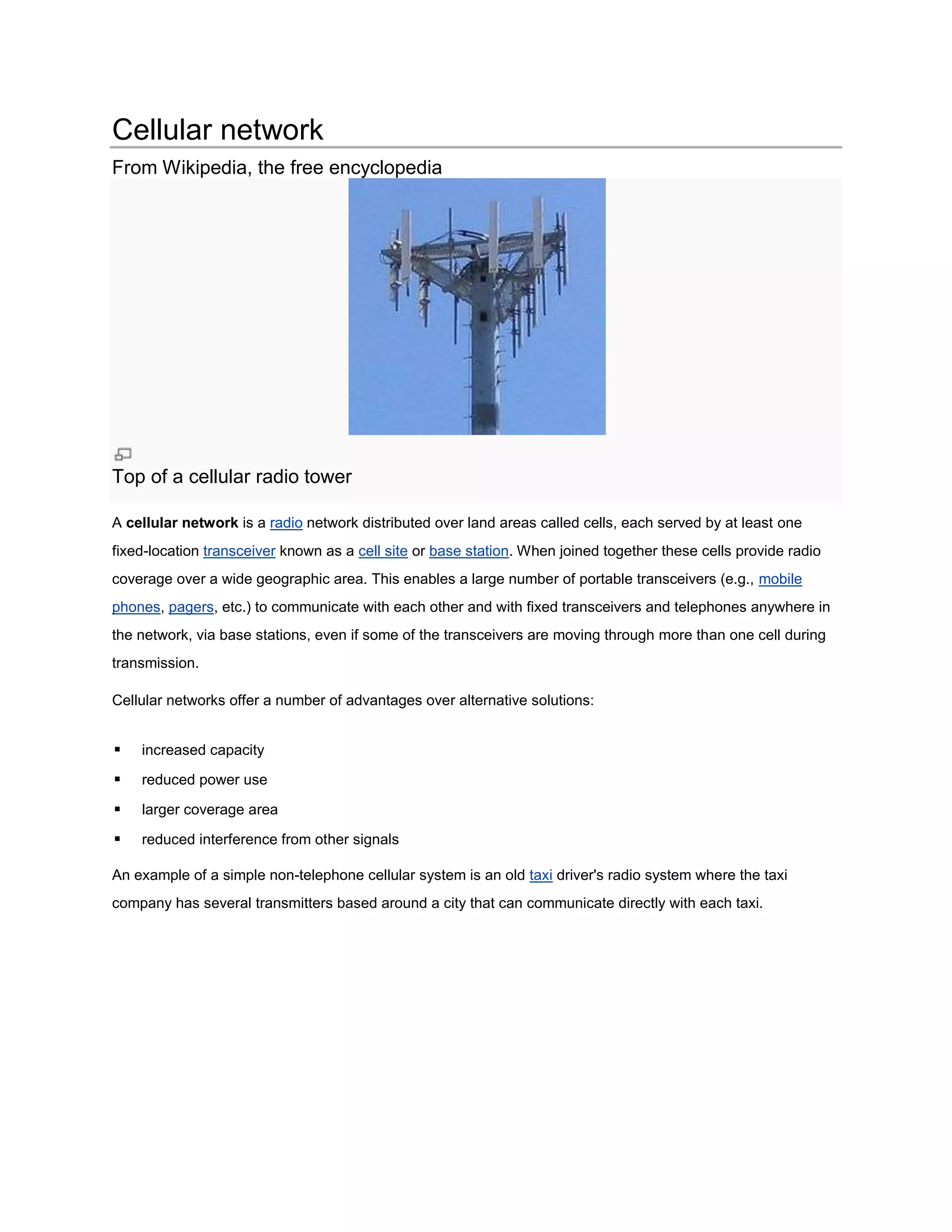
![If the total available bandwidth is B, each cell can only utilize a number of frequency channels
corresponding to a bandwidth of B/K, and each sector can use a bandwidth of B/NK.
Code division multiple access-based systems use a wider frequency band to achieve the same rate of
transmission as FDMA, but this is compensated for by the ability to use a frequency reuse factor of 1, for
example using a reuse pattern of 1/1. In other words, adjacent base station sites use the same
frequencies, and the different base stations and users are separated by codes rather than frequencies.
While N is shown as 1 in this example, that does not mean the CDMA cell has only one sector, but rather
that the entire cell bandwidth is also available to each sector individually.
Depending on the size of the city, a taxi system may not have any frequency-reuse in its own city, but
certainly in other nearby cities, the same frequency can be used. In a big city, on the other hand,
frequency-reuse could certainly be in use.
Recently also orthogonal frequency-division multiple access based systems such as LTE are being
deployed with a frequency reuse of 1. Since such systems do not spread the signal across the frequency
band, inter-cell radio resource management is important to coordinates resource allocation between
different cell sites and to limit the inter-cell interference. There are various means of Inter-cell Interference
Coordination (ICIC) already defined in the standard.[2] Coordinated scheduling, multi-site MIMO or multi-
site beam forming are other examples for inter-cell radio resource management that might be standardized
in the future.
Directional antennas](https://image.slidesharecdn.com/cellularnetwork-wikipediathefreeencyclopedia-120114185734-phpapp01/85/Cellular-network-wikipedia-the-free-encyclopedia-4-320.jpg)
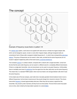
![Cellular telephone frequency reuse pattern. See U.S. Patent 4,144,411
Although the original 2-way-radio cell towers were at the centers of the cells and were omni-directional, a
cellular map can be redrawn with the cellular telephone towers located at the corners of the hexagons
where three cells converge.[3] Each tower has three sets of directional antennas aimed in three different
directions with 120 degrees for each cell (totaling 360 degrees) and receiving/transmitting into three
different cells at different frequencies. This provides a minimum of three channels (from three towers) for
each cell. The numbers in the illustration are channel numbers, which repeat every 3 cells. Large cells can
be subdivided into smaller cells for high volume areas.[4]
Broadcast messages and paging
Practically every cellular system has some kind of broadcast mechanism. This can be used directly for
distributing information to multiple mobiles, commonly, for example in mobile telephony systems, the most
important use of broadcast information is to set up channels for one to one communication between the
mobile transceiver and the base station. This is called paging.](https://image.slidesharecdn.com/cellularnetwork-wikipediathefreeencyclopedia-120114185734-phpapp01/85/Cellular-network-wikipedia-the-free-encyclopedia-5-320.jpg)
![Any phone connects to the network via an RBS (Radio Base Station) at a corner of the corresponding cell
which in turn connects to the Mobile switching center (MSC). The MSC provides a connection to the public
switched telephone network (PSTN). The link from a phone to the RBS is called an uplink while the other
way is termed downlink.
Radio channels effectively use the transmission medium through the use of the following multiplexing
schemes: frequency division multiplex (FDM), time division multiplex (TDM), code division
multiplex (CDM), and space division multiplex (SDM). Corresponding to these multiplexing schemes are
the following access techniques: frequency division multiple access (FDMA), time division multiple
access (TDMA), code division multiple access (CDMA), and space division multiple access (SDMA).[5]
Cellular handover in mobile phone networks
Main article: Handoff
As the phone user moves from one cell area to another cell whilst a call is in progress, the mobile station
will search for a new channel to attach to in order not to drop the call. Once a new channel is found, the
network will command the mobile unit to switch to the new channel and at the same time switch the call
onto the new channel.
With CDMA, multiple CDMA handsets share a specific radio channel. The signals are separated by using
a pseudonoise code (PN code) specific to each phone. As the user moves from one cell to another, the
handset sets up radio links with multiple cell sites (or sectors of the same site) simultaneously. This is
known as "soft handoff" because, unlike with traditional cellular technology, there is no one defined point
where the phone switches to the new cell.
In IS-95 inter-frequency handovers and older analog systems such as NMT it will typically be impossible to
test the target channel directly while communicating. In this case other techniques have to be used such
as pilot beacons in IS-95. This means that there is almost always a brief break in the communication while
searching for the new channel followed by the risk of an unexpected return to the old channel.
If there is no ongoing communication or the communication can be interrupted, it is possible for the mobile
unit to spontaneously move from one cell to another and then notify the base station with the strongest
signal.
Cellular frequency choice in mobile phone
networks
Main article: GSM frequency bands
The effect of frequency on cell coverage means that different frequencies serve better for different uses.
Low frequencies, such as 450 MHz NMT, serve very well for countryside coverage. GSM 900 (900 MHz) is](https://image.slidesharecdn.com/cellularnetwork-wikipediathefreeencyclopedia-120114185734-phpapp01/85/Cellular-network-wikipedia-the-free-encyclopedia-8-320.jpg)
![a suitable solution for light urban coverage. GSM 1800 (1.8 GHz) starts to be limited by structural
walls. UMTS, at 2.1 GHz is quite similar in coverage to GSM 1800.
Higher frequencies are a disadvantage when it comes to coverage, but it is a decided advantage when it
comes to capacity. Pico cells, covering e.g. one floor of a building, become possible, and the same
frequency can be used for cells which are practically neighbours.
Cell service area may also vary due to interference from transmitting systems, both within and around that
cell. This is true especially in CDMA based systems. The receiver requires a certain signal-to-noise ratio.
As the receiver moves away from the transmitter, the power transmitted is reduced. As the interference
(noise) rises above the received power from the transmitter, and the power of the transmitter cannot be
increased any more, the signal becomes corrupted and eventually unusable. In CDMA-based systems, the
effect of interference from other mobile transmitters in the same cell on coverage area is very marked and
has a special name, cell breathing.
One can see examples of cell coverage by studying some of the coverage maps provided by real
operators on their web sites. In certain cases they may mark the site of the transmitter, in others it can be
calculated by working out the point of strongest coverage.
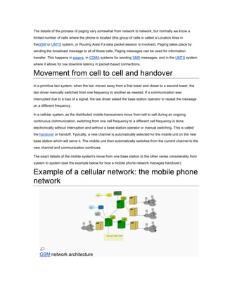
Coverage comparison of different frequencies
Following table shows the dependency of frequency on coverage area of one cell of
a CDMA2000 network:[6]
Frequency (MHz) Cell radius (km) Cell area (km2) Relative Cell Count
450 48.9 7521 1
950 26.9 2269 3.3
1800 14.0 618 12.2
2100 12.0 449 16.2](https://image.slidesharecdn.com/cellularnetwork-wikipediathefreeencyclopedia-120114185734-phpapp01/85/Cellular-network-wikipedia-the-free-encyclopedia-9-320.jpg)

A cellular network divides a geographic area into sections called cells, with each cell served by a fixed base station. This allows portable devices like mobile phones to communicate within the network and across multiple cells. When a device moves between cells, its connection is automatically handed off to the new cell's base station to maintain continuous coverage. Cellular networks reuse frequencies in non-adjacent cells to increase capacity and coverage across a wide area.


![Getting Started with Apache Spark: Big Data Made Simple [Free Meetup]](https://cdn.slidesharecdn.com/ss_thumbnails/apachesparkgettingstarted-260203175547-8361bcc3-thumbnail.jpg?width=640&height=640&fit=bounds)


