Download to read offline


![www.ekeeda.com Contact : 9029006464 Email : care@ekeeda.com
[From equation (2)]
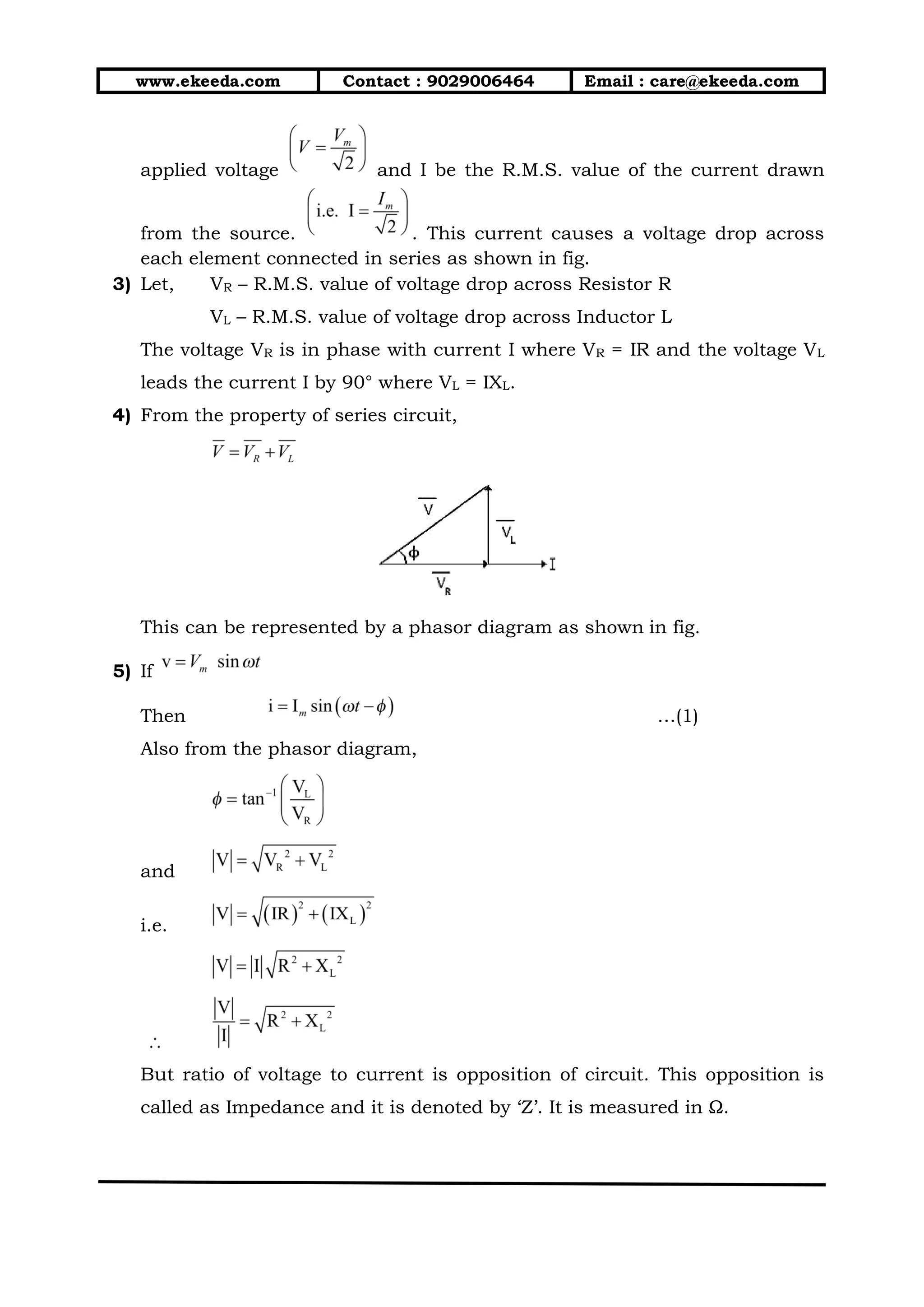
3) During parallel resonance current is minimum and impedance is
maximum.
Hence, and
QUALITY FACTOR OF PARALLEL CIRCUIT
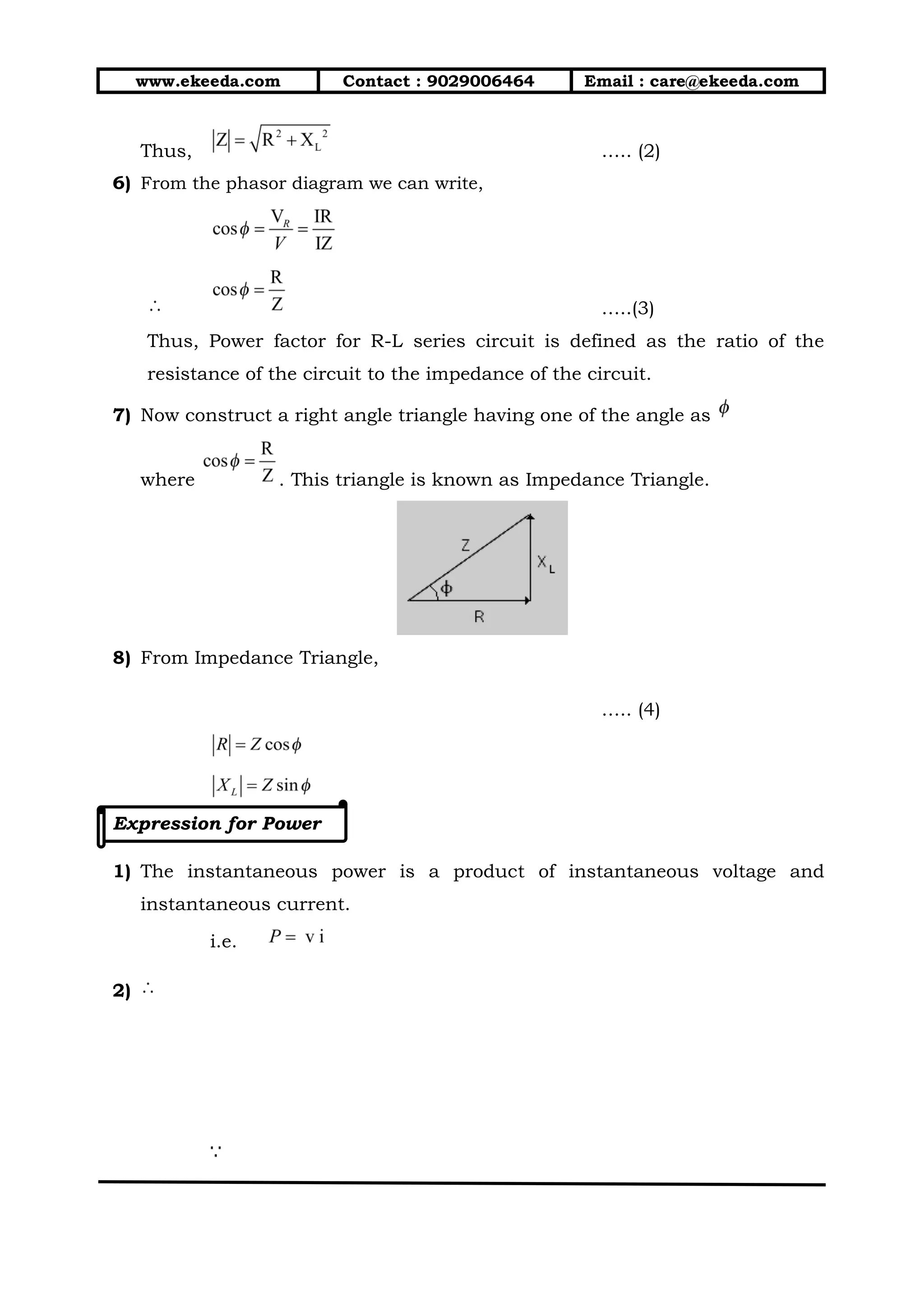
1) Defn : Quality factor of a parallel resonance circuit is defined as the ratio
of current through capacitor to the total current flowing through the
circuit. It is also called as current magnification factor.
….(1)
2)
….(2)
3) If R is negligible then
….(3)](https://image.slidesharecdn.com/a-190318153018/75/A-c-circits-39-2048.jpg)

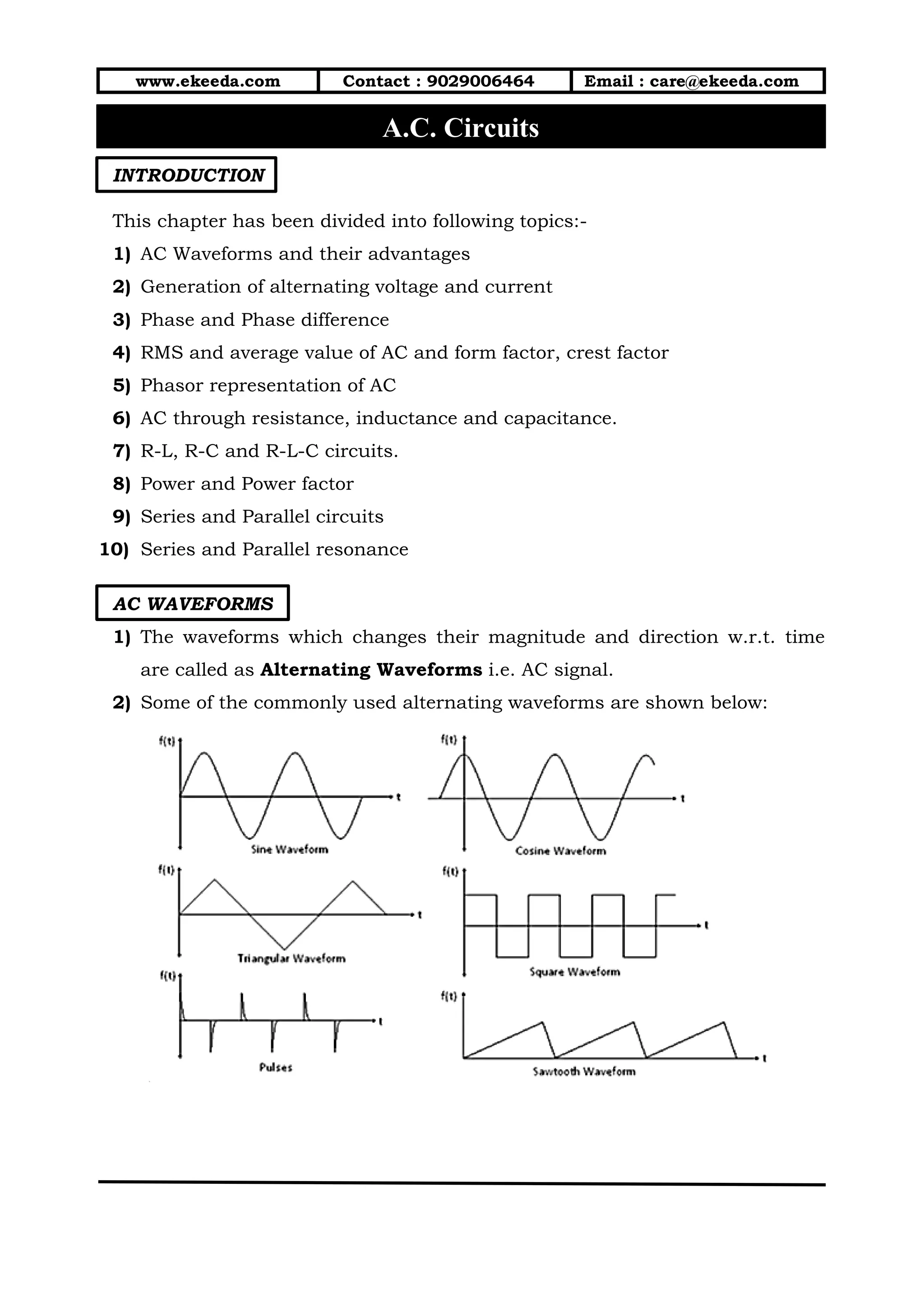
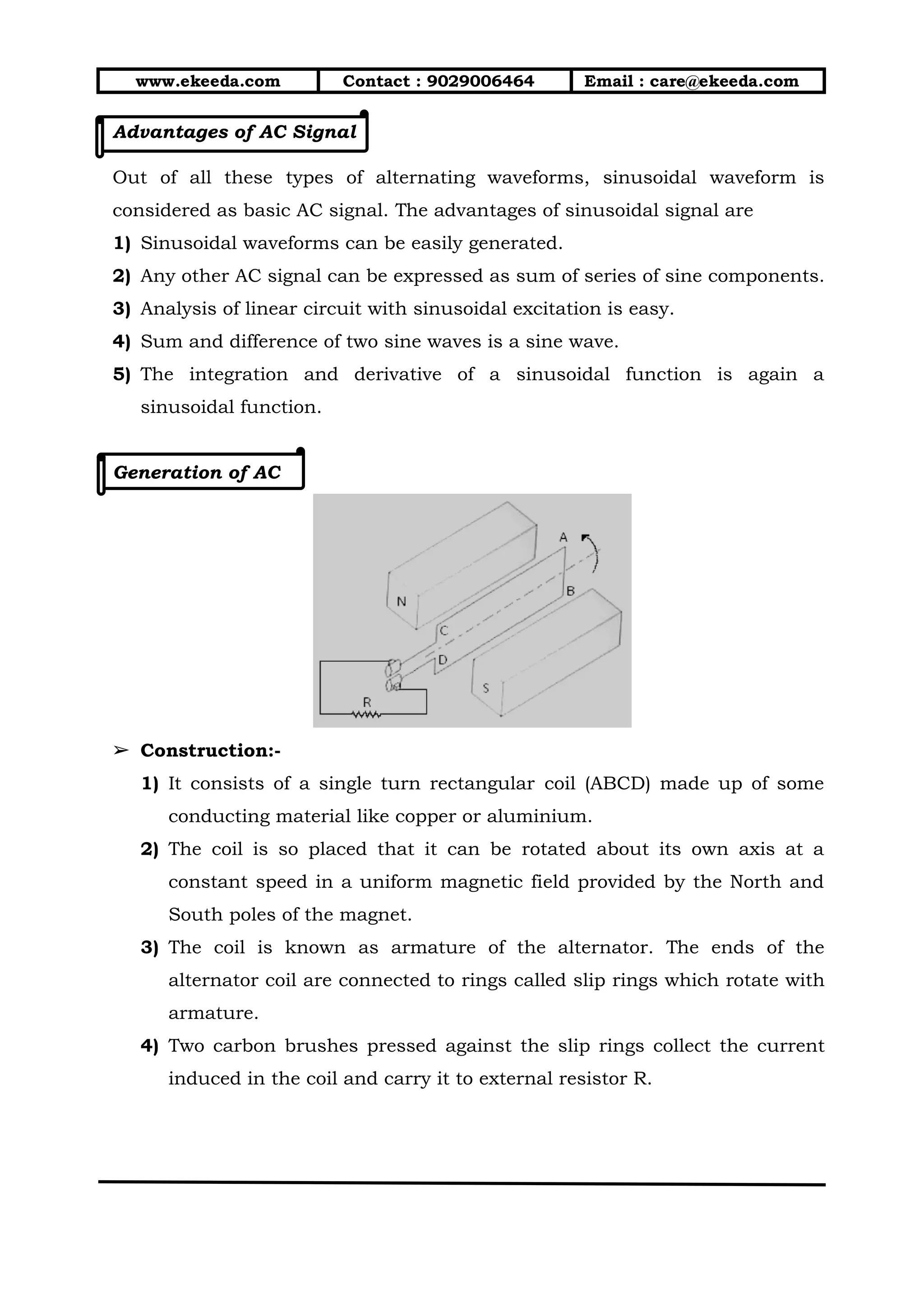
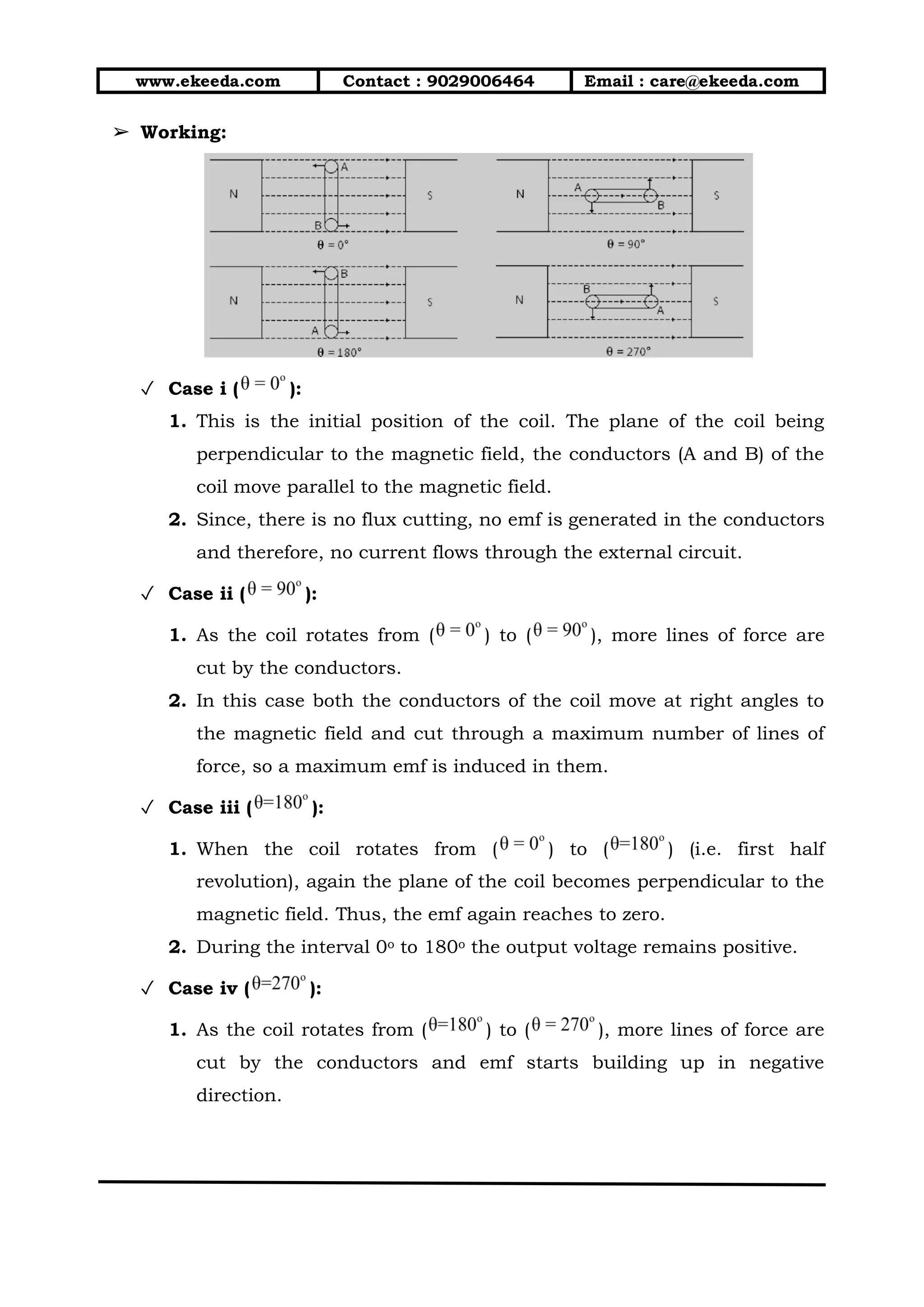
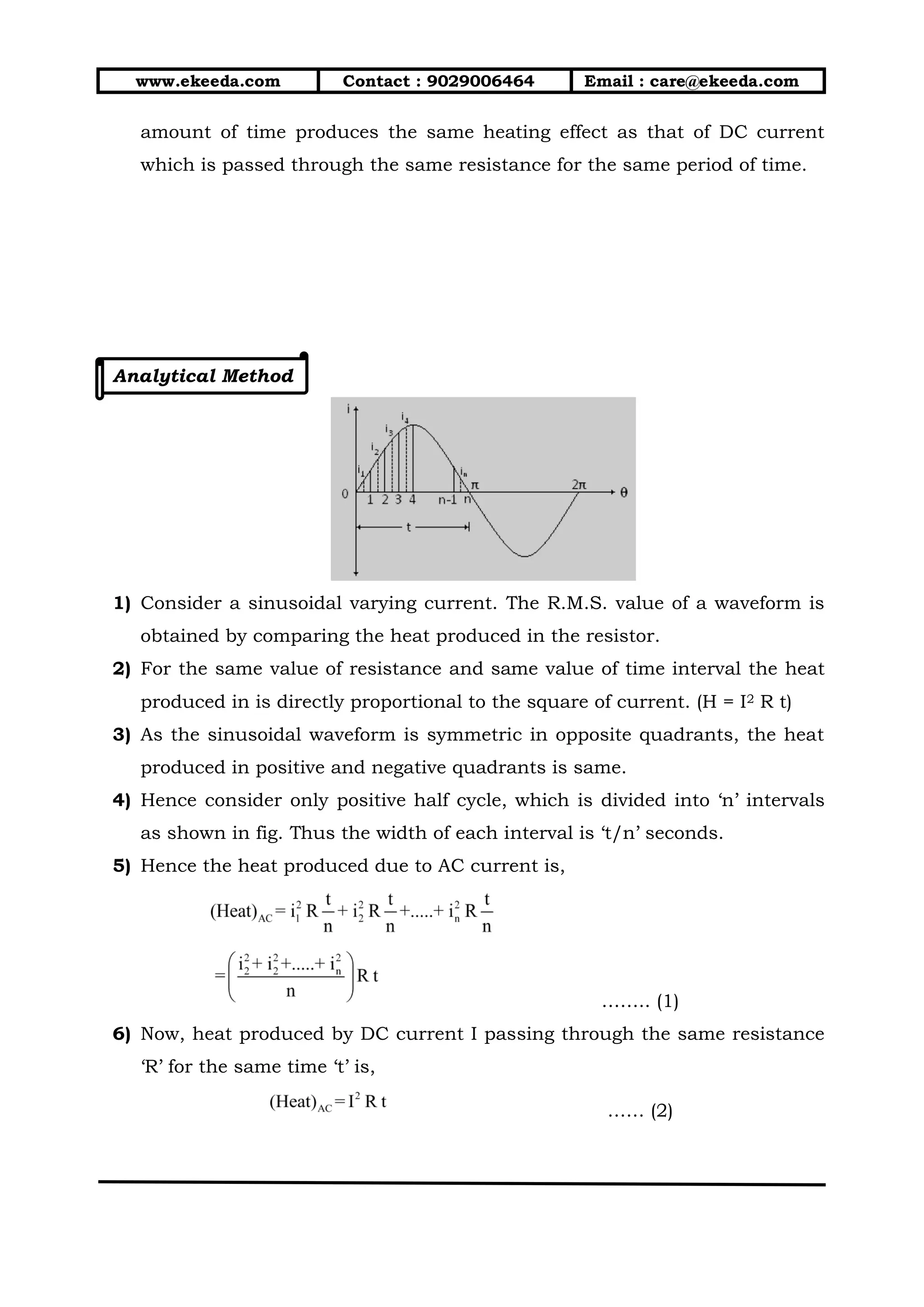
The document provides an introduction to alternating current (AC) circuits. It discusses various AC waveforms and their advantages. It describes how AC is generated using a coil rotating in a magnetic field. Key concepts covered include phase and phase difference, RMS and average values, phasor representation, and the behavior of resistors, inductors and capacitors in AC circuits. Power factor and expressions for power in each circuit element are also examined. The document contains circuit diagrams, equations, and explanations of waveform and phasor diagrams to illustrate AC circuit analysis.


![AC_CIRCUITS[1].pptx](https://cdn.slidesharecdn.com/ss_thumbnails/accircuits1-230813170350-dc7f310b-thumbnail.jpg?width=640&height=640&fit=bounds)


