1) The Biot-Savart law describes the magnetic field generated by a current-carrying conductor. It states that the magnetic field is proportional to the current and inversely proportional to the distance from the current element.
2) The direction of the magnetic field generated by a current element is perpendicular to both the current element and the line from the current element to the point where the magnetic field is calculated.
3) Examples of applying the Biot-Savart law include calculating the magnetic field generated by a circular loop of wire and along the axis of a solenoid. The magnetic fields add linearly for multiple current elements.
![6 Magnetic Effect of Current
genius PHYSICS
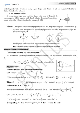
Different cases
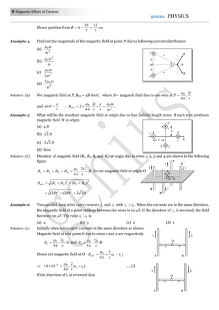
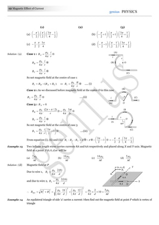
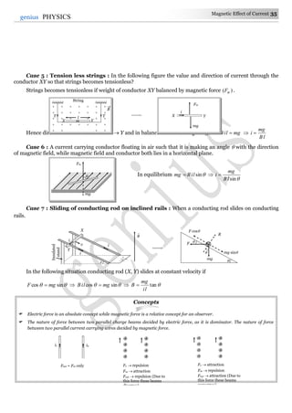
Case 1 : When the linear conductor
XY is of finite length and the point P
lies on it's perpendicular bisector as
shown
21
So )sin2(.
4
0
r
i
B
Case 2 : When the linear conductor
XY is of infinite length and the point
P lies near the centre of the
conductor
1 = 2 = 90o.
So,
r
i
r
i
B oo 2
4
]90sin90[sin
4
00
Case 3 : When the linear conductor
is of infinite length and the point P
lies near the end Y or X
o
901 and o
02 .
So,
r
i
r
i
B oo
4
]0sin90[sin
4
00
Note : When point P lies on axial position of current carrying conductor then magnetic field at P
B = 0
The value of magnetic field induction at a point, on the centre of separation of two linear parallel
conductors carrying equal currents in the same direction is zero.
(6) Zero magnetic field : If in a symmetrical geometry, current enters from one end and exists from the
other, then magnetic field at the centre is zero.
In all cases at centre 0B
Concepts
If a current carrying circular loop (n = 1) is turned into a coil having n identical turns then magnetic field at the centre of
the coil becomes n2 times the previous field i.e. B (n turn) = n2 B(single turn)
When a current carrying coil is suspended freely in earth's magnetic field, it's plane stays in East-West direction.
Magnetic field ( B ) produced by a moving charge q is given by 2
0
3
0 )ˆ(
4
)(
4 r
rvq
r
rvq
B
; where v = velocity of charge
and v << c (speed of light).
i
O
i
O
O
O O
P
i
q v
r
B
O
P
i r
Y
X
P
i
P
i](https://image.slidesharecdn.com/magnetic-effect-of-current-150129234620-conversion-gate01/85/Magnetic-effect-of-current-6-320.jpg)
![Magnetic Effect of Current 13
13genius PHYSICS
(a)
a
i
32
0
(b)
a
i
32
0
(c)
a
i
032
(d) Zero
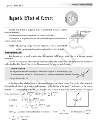
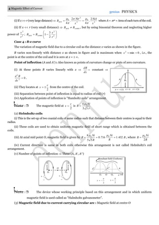
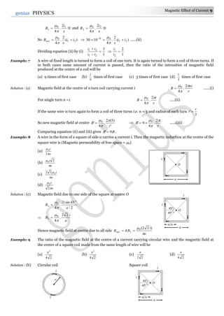
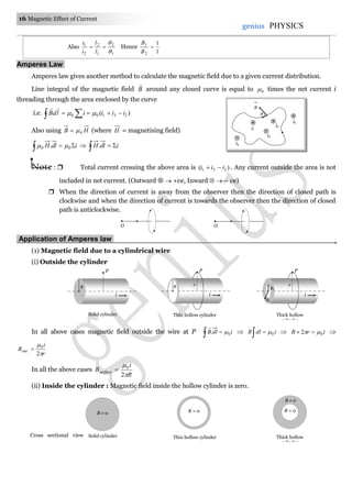
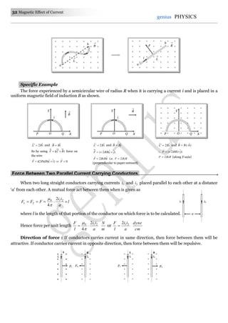
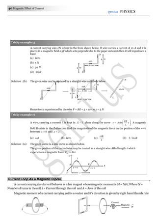
Solution : (b) As shown in the following figure magnetic field at P due to side 1 and side 2 is zero.
Magnetic field at P is only due to side 3,
which is
2
3
30sin2
.
4
0
1
a
i
B
o
a
i
3
2
.
4
0
=
a
i
32
0
Example: 15 A battery is connected between two points A and B on the circumference of a uniform conducting ring of
radius r and resistance R. One of the arcs AB of the ring subtends an angle at the centre. The value of,
the magnetic induction at the centre due to the current in the ring is [IIT-JEE 1995]
(a) Proportional to )180(2 o
(b) Inversely proportional to r
(c) Zero, only if o
180 (d) Zero for all values of
Solution : (d) Directions of currents in two parts are different, so directions of magnetic fields due to these currents are
different.
Also applying Ohm's law across AB 22112211 liliRiRi …..(i)
Also 2
110
1
4 r
li
B
and 2
220
2
4 r
li
B
; 1
22
11
1
2
li
li
B
B
[Using (i)]
Hence, two field are equal but of opposite direction. So, resultant magnetic induction at the centre is zero
and is independent of .
Example: 16 The earth’s magnetic induction at a certain point is 25
/107 mWb
. This is to be annulled by the magnetic
induction at the centre of a circular conducting loop of radius 5 cm. The required current in the loop is
[MP PET 1999; AIIMS 2000]
(a) 0.56 A (b) 5.6 A (c) 0.28 A (d) 2.8 A
Solution : (b) According to the question, at centre of coil HH B
r
i
BB
2
.
4
0
5
2
7
107
)15(
2
10
i
6.5i amp.
Example: 17 A particle carrying a charge equal to 100 times the charge on an electron is rotating per second in a
circular path of radius 0.8 metre. The value of the magnetic field produced at the centre will be 0(
permeability for vacuum) [CPMT 1986]
(a)
0
7
10
(b) 0
17
10
(c) 0
6
10
(d) 0
7
10
Solution : (b) Magnetic field at the centre of orbit due to revolution of charge.
;
)(2
.
4
0
r
q
B
where = frequency of revolution of charge
So,
8.0
)1100(2
4
0
e
B
0
17
10
B .
Example: 18 Ratio of magnetic field at the centre of a current carrying coil of radius R and at a distance of 3R on its
axis is
(a) 1010 (b) 1020 (c) 102 (d) 10
r
r
i2
A
l2
B
l1
i1
P
i i
3
30o
30o
1 2
a
2
3 a
P
i
a
i](https://image.slidesharecdn.com/magnetic-effect-of-current-150129234620-conversion-gate01/85/Magnetic-effect-of-current-13-320.jpg)
![14 Magnetic Effect of Current
genius PHYSICS
Solution : (a) By using ;1
2/3
2
2
r
x
B
B
axis
centre
where x = 3R and r = R 1010)10( 2/3
axis
centre
B
B
.
Example: 19 A circular current carrying coil has a radius R. The distance from the centre of the coil on the axis where
the magnetic induction will be th
8
1
to its value at the centre of the coil, is [MP PMT 1997]
(a)
3
R
(b) 3R (c) R32 (d) R
3
2
Solution : (b) By using
2/3
2
2
1
r
x
B
B
axis
centre
, given r = R and centreaxis BB
8
1
2/3
2
2
18
R
x
3
2/1
2
2
2
1)2(
R
x
2/1
2
2
12
R
x
2
2
14
R
x
Rx 3
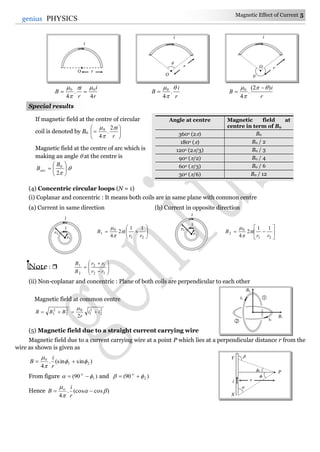
Example: 20 An infinitely long conductor PQR is bent to form a right angle as shown. A current I flows through PQR.
The magnetic field due to this current at the point M is .1H Now, another infinitely long straight
conductor QS is connected at Q so that the current is
2
1
in QR as well as in QS, the current in PQ
remaining unchanged. The magnetic field at M is now .2H The ratio 21 / HH is given by
(a)
2
1
(b) 1
(c)
3
2
(d) 2
Solution : (c) Magnetic field at any point lying on the current carrying conductor is zero.
Here H1 = magnetic field at M due to current in PQ
H2 = magnetic field at M due to R + due to QS + due to PQ = 11
1
2
3
2
0 HH
H
3
2
2
1
H
H
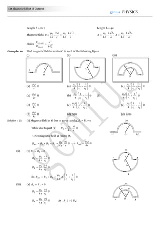
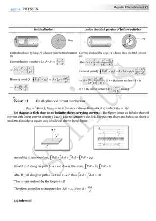
Example: 21 Figure shows a square loop ABCD with edge length a. The resistance of the wire ABC is r and that of ADC
is 2r. The value of magnetic field at the centre of the loop assuming uniform wire is
(a)
a
i
3
2 0
(b)
a
i
3
2 0
(c)
a
i
02
(d)
a
i
02
Solution : (b) According to question resistance of wire ADC is twice that of wire ABC. Hence current flows through ADC
is half that of ABC i.e.
2
1
1
2
i
i
. Also iii 21
3
2
1
i
i and
3
2
i
i
Magnetic field at centre O due to wire AB and BC (part 1 and 2)
2/
45sin2
.
4
10
1
a
i
B
o
a
i10 22
.
4
i
D
B
CA
O
M
P
i +
S
R
–
90o
90o
Q](https://image.slidesharecdn.com/magnetic-effect-of-current-150129234620-conversion-gate01/85/Magnetic-effect-of-current-14-320.jpg)
![Magnetic Effect of Current 15
15genius PHYSICS
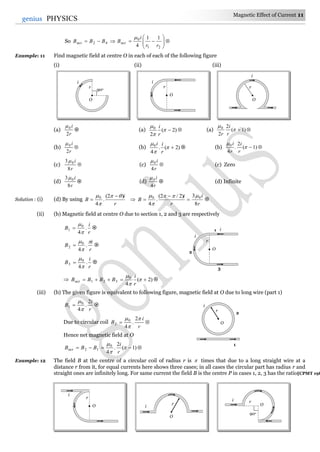
and magnetic field at centre O due to wires AD and DC (i.e. part 3 and 4)
a
i
BB 20
43
22
4
Also i1 = 2i2. So (B1 = B2) > (B3 = B4)
Hence net magnetic field at centre O
)()( 4321 BBBBBnet
a
i
a
i 2
3
22
.
4
3
2
22
.
4
2 00
a
i
a
i
3
2
)12(
3
24
.
4
00
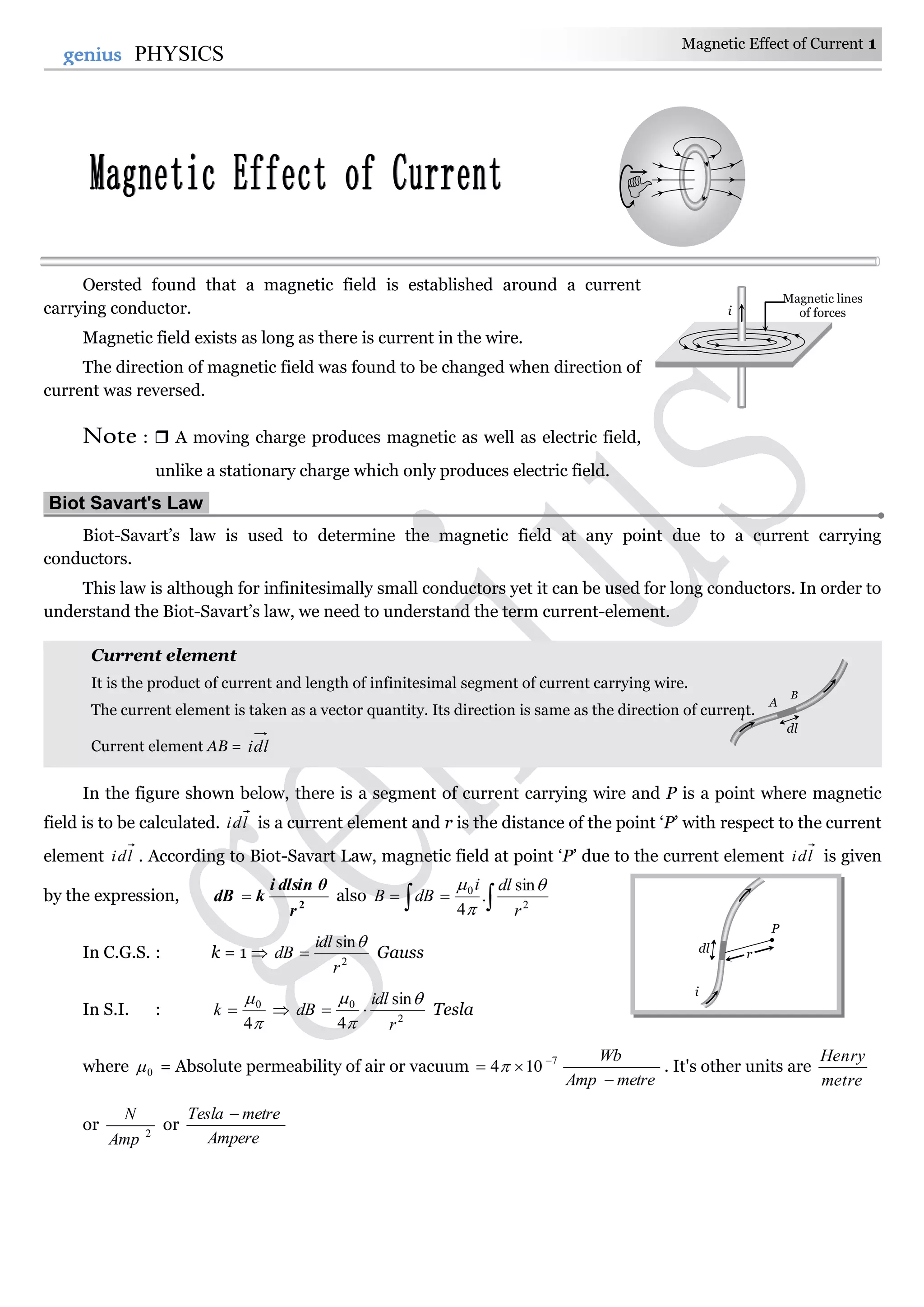
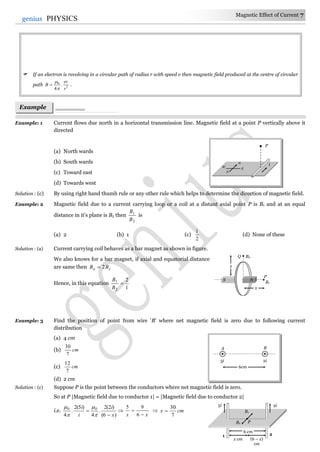
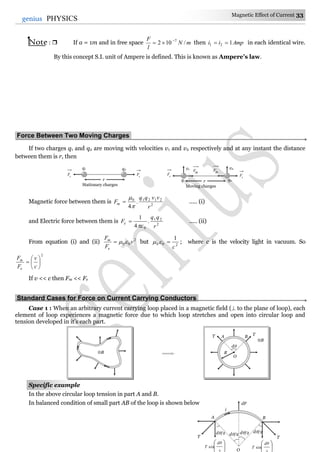
Figure shows a straight wire of length l current i. The magnitude of magnetic field produced by the
current at point P is
(a)
l
i
02
(b)
l
i
4
0
(c)
l
i
8
2 0
(d)
l
i
22
0
Solution: (c) The given situation can be redrawn as follow.
As we know the general formula for finding the magnetic field due to a finite length wire
)sin(sin.
4
21
0
r
i
B
Here 1 = 0o, = 45o
l
i
r
i
B oo
2
.
4
)45sin0(sin.
4
00
l
i
B
8
2 0
A cell is connected between the points A and C of a circular conductor ABCD of centre 'O' with
angle AOC = 60°, If 1B and 2B are the magnitudes of the magnetic fields at O due to the currents
in ABC and ADC respectively, the ratio
2
1
B
B
is [KCET (Engg./ Med.) 1999]
(a) 0.2
(b) 6
(c) 1
(d) 5
Solution: (c)
r
i
B
.
4
0
iB
2
1
2
1
2
1
i
i
B
B
Tricky example: 2
Tricky example: 1
l
i
l
P
45o
l
i
l
P
i
D
B
CA
(1) (2)
(3) (4)
i1
i2 O
1A
i2
300o
1
2
60o
i1
O
1A
i2
300o
B
CA
D
60o
i1
O](https://image.slidesharecdn.com/magnetic-effect-of-current-150129234620-conversion-gate01/85/Magnetic-effect-of-current-15-320.jpg)
![18 Magnetic Effect of Current
genius PHYSICS
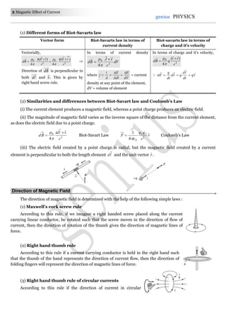
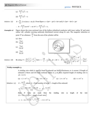
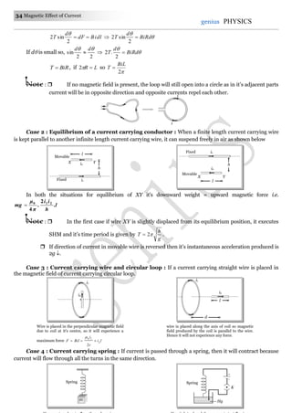
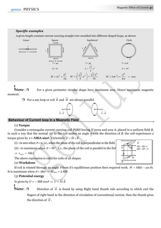
A cylinderical coil of many tightly wound turns of insulated wire with generally diameter of the coil
smaller than its length is called a solenoid.
One end of the solenoid behaves like the north pole and opposite end behaves like the south pole. As the
length of the solenoid increases, the interior field becomes more uniform and the external field becomes
weaker.
A magnetic field is produced around and within the solenoid. The magnetic field within the solenoid is
uniform and parallel to the axis of solenoid.
(i) Finite length solenoid : If N = total number of turns,
l = length of the solenoid
n = number of turns per unit length
l
N
Magnetic field inside the solenoid at point P is given by ]sin)[sin2(
4
0
niB
(ii) Infinite length solenoid : If the solenoid is of infinite length and the point is well inside the
solenoid i.e. )2/( .
So niμBin 0
(ii) If the solenoid is of infinite length and the point is near one end i.e. 0 and )2/(
So )(
2
1
0niμBend
Note : Magnetic field outside the solenoid is zero.
inend BB
2
1
(4) Toroid : A toroid can be considered as a ring shaped closed solenoid. Hence it is like an endless
cylindrical solenoid.
Consider a toroid having n turns per unit length
Let i be the current flowing through the toroid (figure). The magnetic lines of force mainly remain in the
core of toroid and are in the form of concentric circles. Consider such a circle of mean radius r. The circular
closed path surrounds N loops of wire, each of which carries a current i therefore from netildB 0.
B
NS
i iSolenoid
B = 0
P
r
r
Core
Winding
i
O
r
B
dl
P](https://image.slidesharecdn.com/magnetic-effect-of-current-150129234620-conversion-gate01/85/Magnetic-effect-of-current-18-320.jpg)
![Magnetic Effect of Current 19
19genius PHYSICS
NirB 0)2( ni
r
Ni
B o
2
0
where
r
N
n
2
For any point inside the empty space surrounded by toroid and outside the toroid, magnetic field B is zero
because the net current enclosed in these spaces is zero.
Concepts
The line integral of magnetising field )(H for any closed path called magnetomotive force (MMF). It's S.I. unit is amp.
Ratio of dimension of e.m.f. to MMF is equal to the dimension of resistance.
Biot-Savart law is valid for asymmetrical current distributions while Ampere's law is valid for symmetrical current
distributions.
Biot-Savart law is based only on the principle of magnetism while Ampere's laws is based on the principle of
electromagnetism.
Example: 22 A long solenoid has 200 turns per cm and carries a current of 2.5 A. The magnetic field at its centre is
[0 = 4 10–7 Wb/m2] [MP PET 2000]
(a) 3.14 10–2 Wb/m2 (b) 6.28 10–2 Wb/m2 (c) 9.42 10–2 Wb/m2 (d) 12.56 10–2 Wb/m2
Solution : (b) 22
2
7
0 /1028.65.2
10
200
104 mWbniB
.
Example: 23 A long solenoid is formed by winding 20 turns/cm. The current necessary to produce a magnetic field of
20 mili tesla inside the solenoid will be approximately
amperemetreTesla /-10
4
70
[MP PMT 1994]
(a) 8.0 A (b) 4.0 A (c) 2.0 A (d) 1.0 A
Solution : (a) niB 0 ; where
cm
turn
n
10
20
=
m
turn
2000 . So, 5
1020
i 20004 .8Ai
Example: 24 Two solenoids having lengths L and 2L and the number of loops N and 4N, both have the same current,
then the ratio of the magnetic field will be [CPMT 1994]
(a) 2:1 (b) 1:2 (c) 4:1 (d) 1:4
Solution : (a) i
L
N
B 0
L
N
B .
2
12
41
2
2
1
2
1
L
l
N
N
L
L
N
N
B
B
Example: 25 The average radius of a toroid made on a ring of non-magnetic material is 0.1 m and it has 500 turns. If it
carries 0.5 ampere current, then the magnetic field produced along its circular axis inside the toroid will
be
(a) 2
1025
Tesla (b) 2
105
Tesla (c) 4
1025
Tesla (d) 4
105
Tesla
Solution : (d) niB 0 ; where
R
N
n
2
5.0
1.02
500
104 7
B .105 4
T
Example: 26 For the solenoid shown in figure. The magnetic field at point P is
(a) )13(
4
0
ni
(b)
4
3 0 ni
Example
s
n turn
30o 60o
P](https://image.slidesharecdn.com/magnetic-effect-of-current-150129234620-conversion-gate01/85/Magnetic-effect-of-current-19-320.jpg)
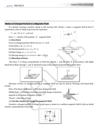
 When Ev
, and B
all the three are collinear : In this situation as the particle is moving parallel or
antiparallel to the field, the magnetic force on it will be zero and only electric force will act and so
m
Eq
m
F
a
The particle will pass through the field following a straight line path (parallel field) with change in its
speed. So in this situation speed, velocity, momentum kinetic energy all will change without change in direction
of motion as shown
(ii) When E is parallel to B and both these fields are perpendicular to v then : eF is
perpendicular to mF and they cannot cancel each other. The path of charged particle is curved in both these
fields.
(iii) E,v and B are mutually perpendicular : In this situation if E
and B
are such that
0 me FFF
i.e., 0)/( mFa
as shown in figure, the particle will pass through the field with same velocity.
And in this situation, as me FF i.e., qvBqE BEv /
This principle is used in ‘velocity-selector’ to get a charged beam having a specific velocity.
Note : From the above discussion, conclusion is as follows
If E = 0, B = 0, so F = 0.
If E = 0, B 0, so F may be zero (if o
0 or o
180 ).
If E 0, B 0, so F = 0 (if |||| me FF
and their directions are opposite)
If E 0, B = 0, so F 0 (because constantv
).
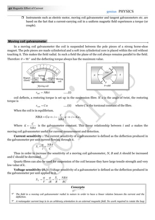
Cyclotron.
Cyclotron is a device used to accelerated positively charged particles (like, -particles, deutrons etc.) to
acquire enough energy to carry out nuclear disintegration etc. t is based
on the fact that the electric field accelerates a charged particle and the
magnetic field keeps it revolving in circular orbits of constant
frequency. Thus a small potential difference would impart if
Target
High frequency
oscillator
Energetic
proton beam
W
N
D1
S
D2
E
B
v
q
q
E
B
v
v
z
x
Fe
+ q
Fm
+ q
y
E
B
](https://image.slidesharecdn.com/magnetic-effect-of-current-150129234620-conversion-gate01/85/Magnetic-effect-of-current-24-320.jpg)
![26 Magnetic Effect of Current
genius PHYSICS
Concepts
The energy of a charged particle moving in a uniform magnetic field does not change because it experiences a force in a
direction, perpendicular to it's direction of motion. Due to which the speed of charged particle remains unchanged and
hence it's K.E. remains same.
Magnetic force does no work when the charged particle is displaced while electric force does work in displacing the
charged particle.
Magnetic force is velocity dependent, while electric force is independent of the state of rest or motion of the charged
particle.
If a particle enters a magnetic field normally to the magnetic field, then it starts moving in a circular orbit. The point at
which it enters the magnetic field lies on the circumference. (Most of us confuse it with the centre of the orbit)
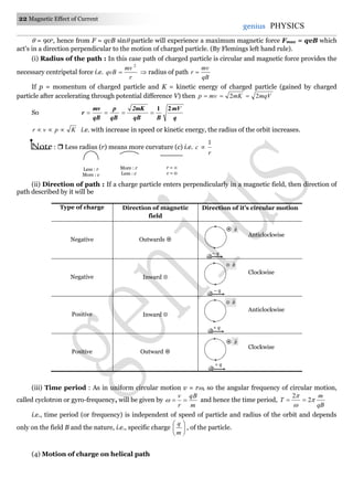
Deviation of charged particle in magnetic field : If a charged particle (q, m) enters a uniform magnetic field
B (extends upto a length x) at right angles with speed v as shown in figure.
The speed of the particle in magnetic field does not change. But it gets deviated in the magnetic field.
Deviation in terms of time t; t
m
Bq
t
Deviation in terms of length of the magnetic field ;
r
x1
sin . This relation can be used only when x r .
For x > r, the deviation will be 180o as shown in the following figure
Example: 28 Electrons move at right angles to a magnetic field of 2
105.1
Tesla with a speed of ./106 27
sm If the
specific charge of the electron is 11
107.1 Coul/kg. The radius of the circular path will be [BHU 2003]
(a) 2.9 cm (b) 3.9 cm (c) 2.35 cm (d) 3 cm
Solution : (c)
qB
mv
r
211
27
105.11017
106
.)/(
Bmq
v
m2
1035.2
.35.2 cm
Example: 29 An electron (mass .109 31
kg
charge .106.1 19
coul
) whose kinetic energy is joule18
102.7
is
moving in a circular orbit in a magnetic field of ./109 25
mweber
The radius of the orbit is[MP PMT 2002]
(a) 1.25 cm (b) 2.5 cm (c) 12.5 cm (d) 25.0 cm
Solution : (d)
519
831
10106.1
102.71022
q
q
qB
mK
r cm25.0 cm25 .
Example: 30 An electron and a proton enter a magnetic field perpendicularly. Both have same kinetic energy. Which of
the following is true [MP PET 1999]
(a) Trajectory of electron is less curved (b) Trajectory of proton is less curved
(c) Both trajectories are equally curved (d) Both move on straight line path
Solution : (b) By using
qB
mk
r
2
; For both particles q same, B same, k same
Hence mr
p
e
p
e
m
m
r
r
epep rrmm so
Example
s
B
q, m
v
v
x
v
v
r
x](https://image.slidesharecdn.com/magnetic-effect-of-current-150129234620-conversion-gate01/85/Magnetic-effect-of-current-26-320.jpg)
![Magnetic Effect of Current 27
27genius PHYSICS
Since radius of the path of proton is more, hence it's trajectory is less curved.
Example: 31 A proton and an particles enters in a uniform magnetic field with same velocity, then ratio of the radii
of path describe by them
(a) 2:1 (b) 1:1 (c) 1:2 (d) None of these
Solution : (b) By using
qB
mv
r ; v same, B same
2
m
r
p
pp
q
q
m
m
r
r
2
12
4
p
p
p
p
q
q
m
m
Example: 32 A proton of mass m and charge e is moving in a circular orbit of a magnetic field with energy 1MeV.
What should be the energy of -particle (mass = 4 m and charge = +2e), so that it can revolve in the path
of same radius [BHU 1997]
(a) 1 MeV (b) 4 MeV (c) 2 MeV (d) 0.5 MeV
Solution : (a) By using
qB
mK
r
2
; r same, B same
m
q
K
2
Hence
m
m
q
q
K
K p
pp
2
1
4
2
2
p
p
p
p
m
m
q
q
.1meVKK p
Example: 33 A proton and an particle enter a uniform magnetic field perpendicularly with the same speed. If
proton takes sec25 to make 5 revolutions, then the periodic time for the particle would be [MP PET 1993]
(a) sec50 (b) sec25 (c) sec10 (d) sec5
Solution : (c) Time period of proton sec5
5
25
pT
By using
qB
m
T
2
q
q
m
m
T
T p
pp
p
p
p
p
q
q
m
m
2
4
.sec102 pTT
Example: 34 A particle with 10–11 coulomb of charge and 10–7 kg mass is moving with a velocity of 108 m/s along the y-
axis. A uniform static magnetic field B = 0.5 Tesla is acting along the x-direction. The force on the particle
is
[MP PMT 1997]
(a) 5 10–11 N along iˆ (b) 5 103 N along kˆ (c) 5 10–11 N along jˆ (d) 5 10–4 N along kˆ
Solution : (d) By using )( BvqF ; where jv ˆ10 and iB ˆ5.0
)ˆˆ(105)ˆ5.0ˆ10(10 4811
ijijF
)ˆ(105 4
k
i.e., 4
105
N along .ˆk
Example: 35 An electron is moving along positive x-axis. To get it moving on an anticlockwise circular path in x-y
plane, a magnetic filed is applied
(a) Along positive y-axis (b) Along positive z-axis
(c) Along negative y-axis (d) Along negative z-axis
Solution : (a) The given situation can be drawn as follows
According to figure, for deflecting electron in x-y plane, force must be acting an it towards y-axis.
Hence according to Flemings left hand rule, magnetic field directed along positive y axis.
y
x
z
e–
e–
x-y plane](https://image.slidesharecdn.com/magnetic-effect-of-current-150129234620-conversion-gate01/85/Magnetic-effect-of-current-27-320.jpg)
![28 Magnetic Effect of Current
genius PHYSICS
Example: 36 A particle of charge 18
1016
coulomb moving with velocity 10 m/s along the x-axis enters a region
where a magnetic field of induction B is along the y-axis, and an electric field of magnitude 104 V/m is
along the negative z-axis. If the charged particle continuous moving along the x-axis, the magnitude of B
is [AIEEE 2003]
(a) 23
/10 mWb
(b) 23
/10 mWb (c) 25
/10 mWb (d) 216
/10 mWb
Solution : (b) Particles is moving undeflected in the presence of both electric field as well as magnetic field so it's speed
B
E
v
v
E
B ./10
10
10 23
4
mWb
Example: 37 A particle of mass m and charge q moves with a constant velocity v along the positive x direction. It
enters a region containing a uniform magnetic field B directed along the negative z direction extending
from x = a to x = b. The minimum value of v required so that the particle can just enter the region x > b
is
[IIT-JEE (Screening) 2002]
(a) qbB/m (b) q(b – a)B/m (c) qaB/m (d) q(b+a)B/2m
Solution : (b) As shown in the following figure, the z axis points out of the paper and the magnetic fields is directed
into the paper, existing in the region between PQ and RS. The particle moves in a circular path of radius r
in the magnetic field. It can just enter the region bx for )( qbr
Now )( ab
qb
mv
r
m
Babq
v
)(
m
Babq
v
)(
min
.
Example: 38 At a certain place magnetic field vertically downwards. An electron approaches horizontally towards you
and enters in this magnetic fields. It's trajectory, when seen from above will be a circle which is
(a) Vertical clockwise (b) Vertical anticlockwise
(c) Horizontal clockwise (d) Horizontal anticlockwise
Solution : (c) By using Flemings left hand rule.
Example: 39 When a charged particle circulates in a normal magnetic field, then the area of it's circulation is
proportional to
(a) It's kinetic energy (b) It's momentum
(c) It's charge (d) Magnetic fields intensity
Solution : (a)
qB
mK
r
2
and 2
AqA 22
)2(
bq
mK
A
.KA
Example: 40 An electron moves straight inside a charged parallel plate capacitor at uniform charge density . The
space between the plates is filled with constant magnetic field of induction .B Time of straight line
motion of the electron in the capacitor is
(a)
lB
e
0
(b)
lB0
Q
Y
S
O v x = a x = b
R
X
B
P
l
e–](https://image.slidesharecdn.com/magnetic-effect-of-current-150129234620-conversion-gate01/85/Magnetic-effect-of-current-28-320.jpg)
![Magnetic Effect of Current 29
29genius PHYSICS
(c)
B
e
0
(d)
e
B0
Solution : (b) The net force acting on the electron is zero because it moves with constant velocity, due to it's motion on
straight line.
0 menet FFF |||| me FF evBEe
BB
E
ve
0
o
E
The time of motion inside the capacitor
lB
v
l
t 0
.
Example: 41 A proton of mass 27
1067.1
kg and charge 19
106.1
C is projected with a speed of sm /102 6
at an
angle of 600 to the X-axis. If a uniform magnetic field of 0.104 Tesla is applied along Y-axis, the path of
proton is
(a) A circle of radius = 0.2 m and time period 7
10
s
(b) A circle of radius = 0.1 m and time period 7
102
s
(c) A helix of radius = 0.1 m and time period 7
102
s
(d) A helix of radius = 0.2 m and time period 7
104
s
Solution : (b) By using
qB
mv
r
sin
mr 1.0
104.0106.1
30sin1021567.1
19
627
and it's time period
qB
m
T
2
104.0106.1
101.92
19
31
.sec102 7
Example: 42 A charge particle, having charge q accelerated through a potential difference V enter a perpendicular
magnetic field in which it experiences a force F. If V is increased to 5V, the particle will experience a force
(a) F (b) 5F (c)
5
F
(d) F5
Solution : (d) qVmv 2
2
1
m
qV
v
2
. Also qvBF
m
qV
qBF
2
hence VF which gives .5' FF
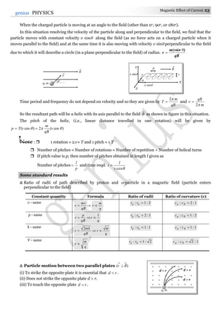
Example: 43 The magnetic field is downward perpendicular to the plane of the paper and a few charged particles are
projected in it. Which of the following is true [CPMT 1997]
(a) Arepresentsprotonand Bandelectron
(b) BothAandBrepresentprotonsbutvelocityofAismorethanthatofB
(c) BothAandBrepresentsprotonsbutvelocityofBismorethanthatofA
(d) BothAandBrepresentelectrons,butvelocityofBismorethanthatofA
Solution : (c) Both particles are deflecting in same direction so they must be of same sign.(i.e., both A and B represents
protons)
By using
qB
mv
r vr
X
Y
v
B
30o
60o
A
B
](https://image.slidesharecdn.com/magnetic-effect-of-current-150129234620-conversion-gate01/85/Magnetic-effect-of-current-29-320.jpg)
![30 Magnetic Effect of Current
genius PHYSICS
From given figure radius of the path described by particle B is more than that of A. Hence .AB vv
Example: 44 Two very long straight, particle wires carry steady currents i and – i respectively. The distance between
the wires is d. At a certain instant of time, a point charge q is at a point equidistant from the two wires, in
the plane of the wires. It's instantaneous velocity v is perpendicular to this plane. The magnitude of the
force due to the magnetic field acting on the charge at this instant is
(a)
d
iqv
2
0
(b)
d
iqv
0
(c)
d
iqv
02
(d) Zero
Solution : (d) According to gives information following figure can be drawn, which shows that direction of magnetic
field is along the direction of motion of charge so net on it is zero.
Example: 45 A metallic block carrying current i is subjected to a uniform magnetic induction B as shown in the figure.
The moving charges experience a force F given by ……. which results in the lowering of the potential of the
face ……. Assume the speed of the carriers to be v [IIT-JEE 1996]
(a) ABCDkeVB ,ˆ
(b) ABCDkeVB ,ˆ
(c) ABCDkeVB ,ˆ
(d) EFGHkeVB ,ˆ
Solution : (c) As the block is of metal, the charge carriers are electrons; so for current along positive x-axis, the electrons
are moving along negative x-axis, i.e. viv
and as the magnetic field is along the y-axis, i.e. jBB ˆ
so )( BvqF for this case yield ]ˆˆ)[( jBiveF
i.e., kevBF ˆ [As kji ˆˆˆ ]
As force on electrons is towards the face ABCD, the electrons will accumulate on it an hence it will acquire
lower potential.
An ionised gas contains both positive and negative ions. If it is subjected simultaneously to an
electric field along the +ve x-axis and a magnetic field along the +z direction then [IIT-JEE (Screening) 2000]
(a) Positive ions deflect towards +y direction and negative ions towards – y direction
(b) All ions deflect towards + y direction
(c) All ions deflect towards – y direction
(d) Positive ions deflect towards – y direction and negative ions towards + y direction.
Solution : (c) As the electric field is switched on, positive ion will start to move along positive x-direction and
negative ion along negative x-direction. Current associated with motion of both types of ions is
along positive x-direction. According to Flemings left hand rule force on both types of ions will be
along negative y-direction.
Force on a Current Carrying Conductor in Magnetic Field.
In case of current carrying conductor in a magnetic field force experienced by its small length element is
BlidFd ; lid = current element )( BldlFd
× × × × × ×
× × × × × × ×
× × × × × ×
× × × × × × ×
× × × × × × ×
× × × × × × ×
dl
i
dF
B
v
d
d/2d/2
q
Tricky example: 4
E G
A
D
v
B
F
e–
C
Fi
d
B
H
y
x
z
B
Y
G
X
I
BA
E
HF
D
C](https://image.slidesharecdn.com/magnetic-effect-of-current-150129234620-conversion-gate01/85/Magnetic-effect-of-current-30-320.jpg)
![36 Magnetic Effect of Current
genius PHYSICS
Example: 46 A vertical wire carrying a current in the upward direction is placed in a horizontal magnetic field directed
towards north. The wire will experience a force directed towards
(a) North (b) South (c) East (d) West
Solution : (d) By applying Flemings left hand rule, direction of force is found towards west.
Example: 47 3 A of current is flowing in a linear conductor having a length of 40 cm. The conductor is placed in a
magnetic field of strength 500 gauss and makes an angle of 30o with the direction of the field. It
experiences a force of magnitude
(a) 3 104 N (b) 3 102 N (c) 3 10– 2 N (d) 3 10–4 N
Solution : (c) By using sinBilF F = (500 10–4) 0.4 sin 30o 3 10–2 N.
Example: 48 Wires 1 and 2 carrying currents 1t and 2t respectively are inclined at an angle to each other. What is
the force on a small element dl of wire 2 at a distance of r from 1 (as shown in figure) due to the magnetic
field of wire 1 [AIEEE 2002]
(a)
tan,
2
21
0
dlii
r
(b)
sin,
2
21
0
dlii
r
(c)
cos,
2
21
0
dlii
r
(d)
sin,
4
21
0
dlii
r
Solution : (c) Length of the component dl which is parallel to wire (1) is dl cos , so force on it
r
dlii
dl
r
ii
F
2
cos
)cos(
2
4
210210
.
Example: 49 A conductor PQRSTU, each side of length L, bent as shown in the figure, carries a current i and is placed in
a uniform magnetic induction B directed parallel to the positive Y-axis. The force experience by the wire
and its direction are
(a) 2iBL directed along the negative Z-axis
(b) 5iBL directed along the positive Z-axis
(c) iBL direction along the positive Z-axis
(d) 2iBL directed along the positive Z-axis
Solution : (c) As PQ and UT are parallel to Q, therefore 0 UTPQ FF
The current in TS and RQ are in mutually opposite direction. Hence, 0 RQTS FF
Therefore the force will act only on the segment SR whose value is Bil and it’s direction is +z.
Alternate method :
Example
s
BHi
N
W
ES
F
Z
R
Q P
Y
UT
B
i
S
X
B
Z
R
Q P
Y
UT
i
S
X
P
U
F
i
B
i1 i2
dl
r
](https://image.slidesharecdn.com/magnetic-effect-of-current-150129234620-conversion-gate01/85/Magnetic-effect-of-current-36-320.jpg)
![Magnetic Effect of Current 37
37genius PHYSICS
The given shape of the wire can be replaced by a straight wire of length l between P and U as shown below
Hence force on replaced wire PU will be BilF
and according to FLHR it is directed towards +z-axis
Example: 50 A conductor in the form of a right angle ABC with AB = 3cm and BC = 4 cm carries a current of 10 A.
There is a uniform magnetic field of 5T perpendicular to the plane of the conductor. The force on the
conductor will be
(a) 1.5 N (b) 2.0 N (c) 2.5 N (d) 3.5 N
Solution : (c) According to the question figure can be drawn as shown below.
Force on the conductor ABC = Force on the conductor AC
= 5 10 (5 10–2)
= 2.5 N
Example: 51 A wire of length l carries a current i along the X-axis. A magnetic field exists which is given as 0BB
( )ˆˆˆ kji T. Find the magnitude of the magnetic force acting on the wire
(a) ilB0 (b) 20 liB (c) liB02 (d) liB0
2
1
Solution : (b) By using )( BliF )]ˆˆˆ(ˆ[)]ˆˆˆ(ˆ[ 00 kjiiilBkjiBiliF
]ˆˆˆˆˆˆ[0 kijiiiilBF ]ˆˆ[0 jkilB }ˆˆˆ,ˆˆˆ,0ˆˆ{ jkikjiii
It's magnitude ilBF 02
Example: 52 A conducting loop carrying a current i is placed in a uniform magnetic field pointing into the plane of the
paper as shown. The loop will have a tendency to [IIT-JEE (Screening) 2003]]
(a) Contract (b) Expand
(c) Move towards + ve x-axis (d) Move towards – ve x-axis
Solution : (b) Net force on a current carrying loop in uniform magnetic field is zero. Hence the loop can't translate. So,
options (c) and (d) are wrong. From Flemings left hand rule we can see that if
magnetic field is perpendicular to paper inwards and current in the loop is
clockwise (as shown) the magnetic force mF on each element of the loop is
radially outwards, or the loops will have a tendency to expand.
Example: 53 A circular loop of radius a, carrying a current i, is placed in a two-dimensional magnetic field. The centre
of the loop coincides with the centre of the field. The strength of the magnetic field at the periphery of the
loop is B. Find the magnetic force on the wire
(a) Bai
(b) Bai4
(c) Zero
(d) Bai2
Solution : (d) The direction of the magnetic force will be vertically downwards at each element of the wire.
Thus F = Bil = Bi (2a) = 2iaB.
Example: 54 A wire abc is carrying current i. It is bent as shown in fig and is placed in a uniform magnetic field of
magnetic induction B. Length ab = l and abc = 45o. The ratio of force on ab and on bc is
i
Y
Ba
i
Y
X
Fm
A
B C
3 cm
4 cm
10 A B
A
C
10 A F
B](https://image.slidesharecdn.com/magnetic-effect-of-current-150129234620-conversion-gate01/85/Magnetic-effect-of-current-37-320.jpg)
![38 Magnetic Effect of Current
genius PHYSICS
(a)
2
1
(b) 2 (c) 1 (d)
3
2
Solution : (c) Force on portion ab of wire F1 = Bil sin 90o = Bil
Force on portion bc of wire F2 = Bil
l
Bi o
45sin
2
. So 1
2
1
F
F
.
Example: 55 Current i flows through a long conducting wire bent at right angle as shown in figure. The magnetic field
at a point P on the right bisector of the angle XOY at a distance r from O is
(a)
r
i
0
(b)
r
i
02
(c) )12(
4
0
r
i
(d) )12(
2
.
4
0
r
i
Solution : (d) By using )sin(sin.
4
21
0
r
i
B , from figure
2
45sin
r
rd o
Magnetic field due to each wire at P )90sin45(sin
)2/(
.
4
0 oo
r
i
B
)12(.
4
0
r
i
Hence net magnetic field at P )12(.
2
)12(.
4
2 00
r
i
r
i
Bnet
Example: 56 A long wire A carries a current of 10 amp. Another long wire B, which is parallel to A and separated by 0.1
m from A, carries a current of 5 amp. in the opposite direction to that in A. What is the magnitude and
nature of the force experienced per unit length of B [ 7
0 104
weber/amp – m]
(a) Repulsive force of mN /10 4
(b) Attractive force of mN /10 4
(c) Repulsive force of mN /102 5
(d) Attractive force of mN /102 5
Solution : (a) By using
a
ii
l
F 210 2
.
4
N
l
F 47
10
1.0
5102
10
Wires are carrying current in opposite direction so the force will be repulsive.
Example: 57 Three long, straight and parallel wires carrying currents are arranged as shown in figure. The force
experienced by 10 cm length of wire Q is [MP PET 1997]
(a) 1.4×10⁻⁴ N towards the right
(b) 1.4×10⁻⁴ N towards the left
(c) 2.6 × 10⁻⁴ N to the right
(d) 2.6×10⁻⁴ N to the left
Solution : (a) Force on wire Q due to R ; )1010(
)102(
10202
10 2
2
7
RF = 2 10–4 m (Repulsive)
Force on wire Q due to P ; )1010(
)1010(
3010
210 2
2
7
PF = 0.6 10–4 N (Repulsive)
10 A 5 A
0.1 m
10cm2cm
R Q
10 A20 A 30 A
P
45o
P
X
Y
r
i
O
d
i
45o
d
P
45o
45o
X
Y
r
O
l
B
45o
a
ci
i
b](https://image.slidesharecdn.com/magnetic-effect-of-current-150129234620-conversion-gate01/85/Magnetic-effect-of-current-38-320.jpg)
![Magnetic Effect of Current 39
39genius PHYSICS
Hence net force Fnet = FR – FP = 2 10–4 – 0.6 10–4 = 1.4 10–4 N (towards right i.e. in the direction of
RF .
Example: 58 What is the net force on the coil [DCE 2000]
(a) N7
1025
moving towards wire
(b) N7
1025
moving away from wire
(c) N7
1035
moving towards wire
(d) N7
1035
moving away from wire
Solution : (a) Force on sides BC and CD cancel each other.
Force on side AB NFAB
62
2
7
1031015
102
122
10
Force on side CD NFAB
62
2
7
105.01015
1012
122
10
Hence net force on loop = FAB – FCD = 25 10–7 N (towards the wire).
Example: 59 A long wire AB is placed on a table. Another wire PQ of mass 1.0 g and length 50 cm is set to slide on two
rails PS and QR. A current of 50A is passed through the wires. At what distance above AB, will the wire PQ
be in equilibrium
(a) 25 mm
(b) 50 mm
(c) 75 mm
(d) 100 mm
Solution : (a) Suppose in equilibrium wire PQ lies at a distance r above the wire AB
Hence in equilibrium Bilmg il
r
i
mg
2
4
0
5.0
)50(2
101010
2
73
r
mmr 25
Example: 60 An infinitely long, straight conductor AB is fixed and a current is passed through it. Another movable
straight wire CD of finite length and carrying current is held perpendicular to it and released. Neglect
weight of the wire
(a) The rod CD will move upwards parallel to itself
(b) The rod CD will move downward parallel to itself
(c) The rod CD will move upward and turn clockwise at the same time
(d) The rod CD will move upward and turn anti –clockwise at the same time
Solution : (c) Since the force on the rod CD is non-uniform it will experience force and torque. From the left hand side it
can be seen that the force will be upward and torque is clockwise.
2A
2 cm
10 cm
15 cm
B C
A D
FCDFAB
1A
2A
2 cm
10 cm
15 cm
1A
A
50 A
B
P Q
S R
A
B
i1
C D i2
A
B
i1
C D i2](https://image.slidesharecdn.com/magnetic-effect-of-current-150129234620-conversion-gate01/85/Magnetic-effect-of-current-39-320.jpg)
![Magnetic Effect of Current 43
43genius PHYSICS
about an axis perpendicular to it's plane.
Moving coil galvanometer can be made ballistic by using a non-conducting frame (made of ivory or bamboo) instead of a
metallic frame.
Example: 61 A circular coil of radius 4 cm and 20 turns carries a current of 3 ampere. It is placed in a magnetic field of
0.5 T. The magnetic dipole moment of the coil is [MP PMT 2001]
(a) 0.60 A-m2 (b) 0.45 A-m2 (c) 0.3 A-m2 (d) 0.15 A-m2
Solution : (c) M = niA M = 20 3 ( 4 10–2)2 = 0.3 A-m2.
Example: 62 A steady current i flows in a small square loop of wire of side L in a horizontal plane. The loop is now
folded about its middle such that half of it lies in a vertical plane. Let 1 and 2 respectively denote the
magnetic moments due to the current loop before and after folding. Then [IIT-JEE 1993]
(a) 02 (b) 1 and 2 are in the same direction
(c) 2
||
||
2
1
(d)
2
1
||
||
2
1
Solution : (c) Initially Finally
M = magnetic moment due to each part
222
1
2
iL
L
L
i
2
2
2
2 11
2
M
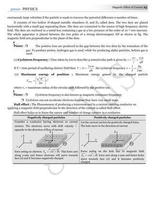
Example: 63 A coil of 50 turns is situated in a magnetic field b = 0.25weber/m2 as shown in figure. A current of 2A is
flowing in the coil. Torque acting on the coil will be
(a) 0.15 N
(b) 0.3 N
(c) 0.45 N
(d) 0.6 N
Solution : (b) Since plane of the coil is parallel to magnetic field. So = 90o
Hence = NBiA sin 90o = NBiA = 50 0.25 2 (12 10–2 10 10–2) = 0.3 N.
Example: 64 A circular loop of area 1 cm2, carrying a current of 10 A, is placed in a magnetic field of 0.1 T perpendicular
to the plane of the loop. The torque on the loop due to the magnetic field is
(a) Zero (b) 10–4 N-m (c) 10–2 N-m (d) 1 N-m
Solution : (a) = NBiA sin ; given = 0 so = 0.
Example: 65 A circular coil of radius 4 cm has 50 turns. In this coil a current of 2 A is flowing. It is placed in a magnetic
field of 0.1 weber/m2. The amount of work done in rotating it through 180o from its equilibrium position
will be
[CPMT 1977]
(a) 0.1 J (b) 0.2 J (c) 0.4 (d) 0.8 J
N S
B
A B
D C
12cm
10 cm
Example
s
L
i
1 = iL2
L
L/2
L/2
L
L
M
2M
M](https://image.slidesharecdn.com/magnetic-effect-of-current-150129234620-conversion-gate01/85/Magnetic-effect-of-current-43-320.jpg)
![44 Magnetic Effect of Current
genius PHYSICS
Solution : (a) Work done in rotating a coil through an angle from it's equilibrium position is W = MB(1 – cos) where = 180o
and M = 50 2 (4 10–2) = 50.24 10–2 A-m2. Hence W = 0.1 J
Example: 66 A wire of length L is bent in the form of a circular coil and current i is passed through it. If this coil is
placed in a magnetic field then the torque acting on the coil will be maximum when the number of turns is
(a) As large as possible (b) Any number (c) 2 (d) 1
Solution : (d) MBmax or Bani 2
max . Let number of turns in length l is n so )2( anl or
n
l
a
2
22
2
max
4 n
Blni
min
2
4 n
iBl
min
max
1
n
1min n
Example: 67 A square coil of N turns (with length of each side equal L) carrying current i is placed in a uniform
magnetic field jBB ˆ
0 as shown in figure. What is the torque acting on the coil
(a) kNiLB ˆ2
0
(b) kNiLB ˆ2
0
(c) jNiLB ˆ2
0
(d) jNiLB ˆ2
0
Solution : (b) The magnetic field is jBB ˆ
0 and the magnetic moment )ˆ( 2
iNLiAim
The torque is given by Bm
jBiiNL ˆˆ
0
2
jiLiNB ˆˆ2
0
kLiNB ˆ2
0
Example: 68 The coil of a galvanometer consists of 100 turns and effective area of 1 square cm. The restoring couple is 10– 8 N-m
rad. The magnetic field between the pole pieces is 5 T. The current sensitivity of this galvanometer will be
[MP PMT 1997]
(a) 5 104 rad/ amp (b) 5 10– 6 per amp (c) 2 10– 7 per amp (d) 5 rad./ amp
Solution : (d) Current sensitivity (Si) =
C
NBA
i
amprad
i
/5
10
105100
8
4
.
Example: 69 The sensitivity of a moving coil galvanometer can be increased by [SCRA 2000]]
(a) Increasing the number of turns in the coil (b) Decreasing the area of the coil
(c) Increasing the current in the coil (d) Introducing a soft iron core inside the coil
Solution : (a) Sensitivity (Si) =
C
NBA
NSi .
The square loop ABCD, carrying a current i, is placed in uniform magnetic field B, as shown. The
loop can rotate about the axis XX'. The plane of the loop makes and angle ( < 90°) with the
direction of B. Through what angle will the loop rotate by itself before the torque on it becomes zero
(a)
(b) 90°–
(c) 90° +
(d) 180°–
Solution : (c) In the position shown, AB is outside and CD is inside the plane of the paper. The Ampere force on
AB acts into the paper. The torque on the loop will be clockwise, as seen from above. The loop must
rotate through an angle (90o + ) before the plane of the loop becomes normal to the direction of B
and the torque becomes zero.
Tricky example: 7
X C
D
A
X
i
B
Z
B
jˆ
kˆ
iˆ
jBB ˆ
0
L
i
X
i](https://image.slidesharecdn.com/magnetic-effect-of-current-150129234620-conversion-gate01/85/Magnetic-effect-of-current-44-320.jpg)