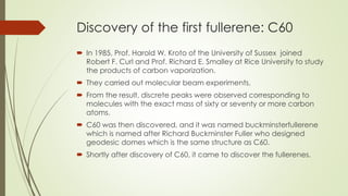
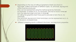
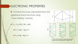
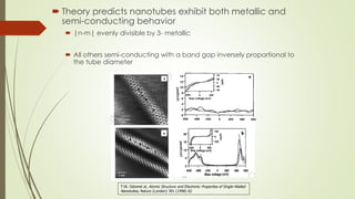
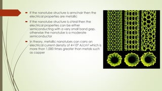
Carbon nanotubes and their applications are discussed. There are several allotropes of carbon including diamond, graphite, buckminsterfullerene (C60), and single-walled carbon nanotubes. Carbon nanotubes are cylindrical forms of carbon that can be single-walled or multi-walled. They are composed of hexagonal networks of carbon atoms and have remarkable mechanical, thermal, and electrical properties. Common synthesis methods for carbon nanotubes include arc discharge, laser ablation, and chemical vapor deposition using metal catalysts.
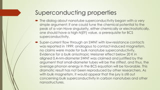
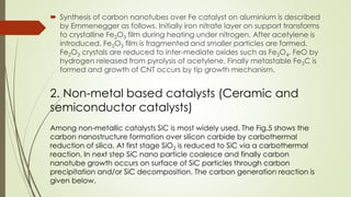
![CARBON
group- 14
period-2
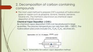
Carbon is the 15th most abundant element in the Earth's crust, and
the fourth most abundant element in the universe by
mass after hydrogen, helium, and oxygen.
It is reactive non metal.
Electron configuration [He] 2s2 2p2
Electrons per shell 2,4 .
tetravalent—making four electrons available to
form covalent chemical bonds
Three isotopes occur naturally, 12C and 13C being stable, while 14C is
a radionuclide, decaying with a half-life of about 5,730 years.](https://image.slidesharecdn.com/copyofcarbonnanotubesyogesh-190206162121/85/carbon-nanotubes-2-320.jpg)
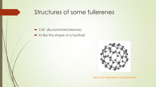

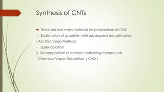
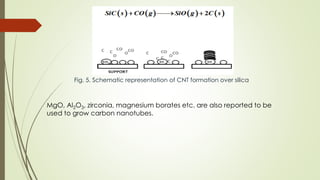
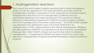
![2. Reaction involving CO/H2
CNTs have been investigated for Fischer –Tropsch reactions, methanol and
higher alcohol synthesis and hydroformylation reactions. Copper promoted
Fe/MWCNT catalyst are active for Fischer-Tropsch synthesis with olefins . Co-
Re/Al2O3 deposited on MWCNT by dip coating exhibited an enhancement
in Fischer-Tropsch activity than observed with a similar system without CNT
arrays. MWCNTs also have been used as promoter for Cu-ZnO-
Al2O3 catalysts for methanol synthesis using H2/CO/CO2 The complex
[HRh(CO)(PPh3)3] has been grafted onto MCWNTs and used for
hydroformylation of propene. Higher conversion and higher regioselectivity
toward n-butaldehyde have been reported for CNT supported catalysts
compared to that activated carbon or carbon molecular sieve supported
catalysts.](https://image.slidesharecdn.com/copyofcarbonnanotubesyogesh-190206162121/85/carbon-nanotubes-35-320.jpg)
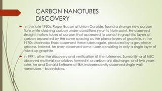
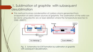
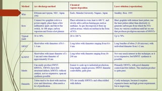
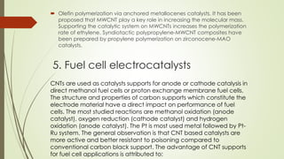
![4. Polymerization
The CNTs have excellent thermal and electrical conductivities and reported to
be used as fillers in polymer based advanced composites. However due to poor
solubility of CNTs, homogeneous dispersion is difficult task. The polymer
functionalized CNTs are prepared following three approaches:
A non-covalent functionalization method in which polymers are produced
by ring opening metathesis polymerization. The coating of hyper branched
polymers on MWCNTs has been obtained via cationic ring opening
polymerization of 3-ethyl-3-(hydroxymethyl)oxetane with a BF3 .Et2O catalyst
A covalent functionalization performed by, first grafting polymerization
initiators onto the tubes through covalent bond and then exposing these CNT
based macro-initiators to the monomer. The polymer is obtained by atom
transfer radical polymerization. The polyethylene-MWCNT composite has
been produced using catalyst grafting procedure by polymerization of
ethylene on [ZrCl2Cp2] MAO/MWCNT where Cp = C5H5 and MAO =
methylaluminoxane .](https://image.slidesharecdn.com/copyofcarbonnanotubesyogesh-190206162121/85/carbon-nanotubes-37-320.jpg)


![Polymer [ बहुलक ] Chemistry Notes PDF - Irfanullah Mehar - JJ Sir Chemistry.pdf](https://cdn.slidesharecdn.com/ss_thumbnails/polymerchemistrynotespdf-irfanullahmehar-jjsirchemistry-260210172118-3f9b37f7-thumbnail.jpg?width=640&height=640&fit=bounds)


