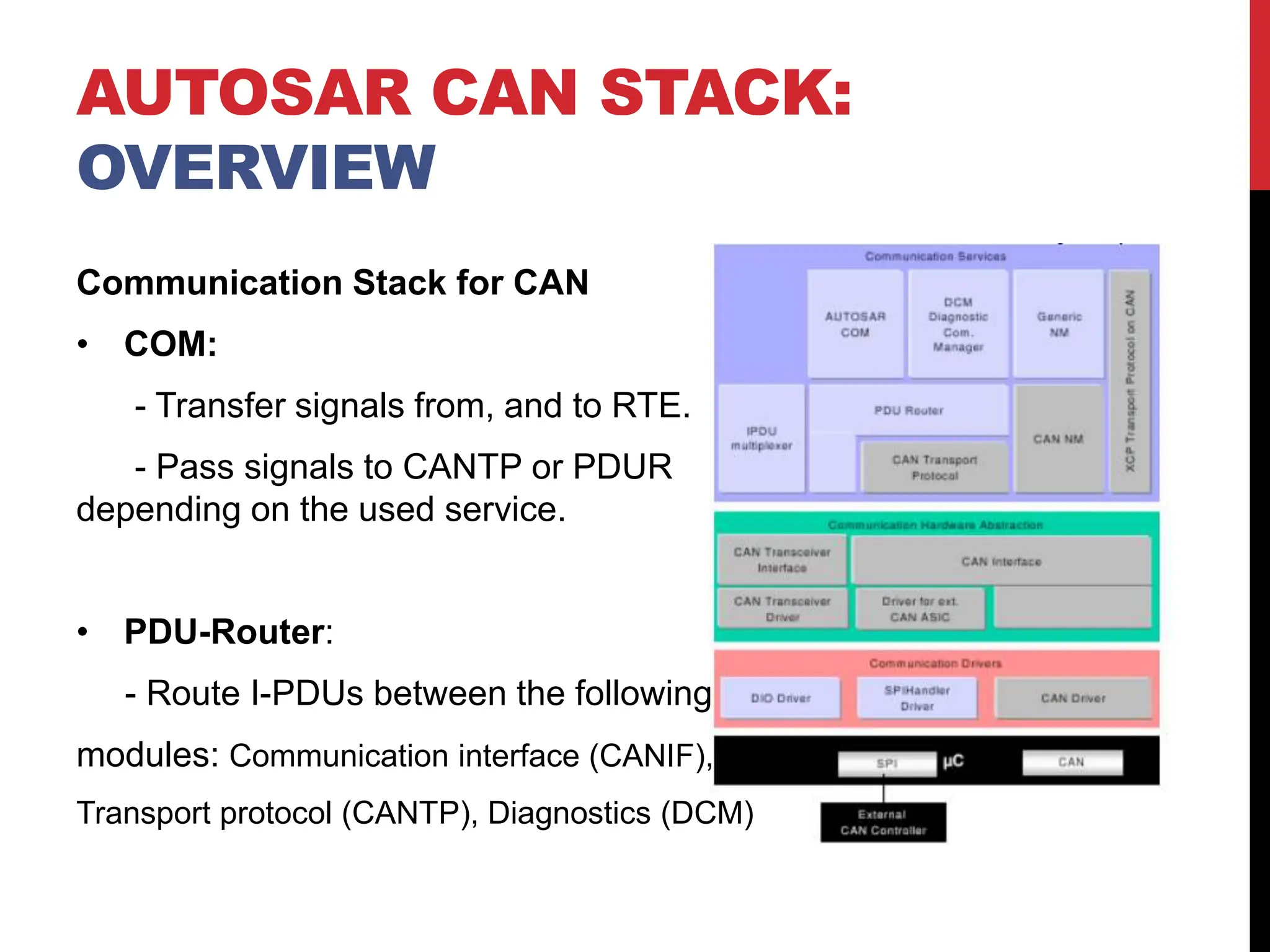
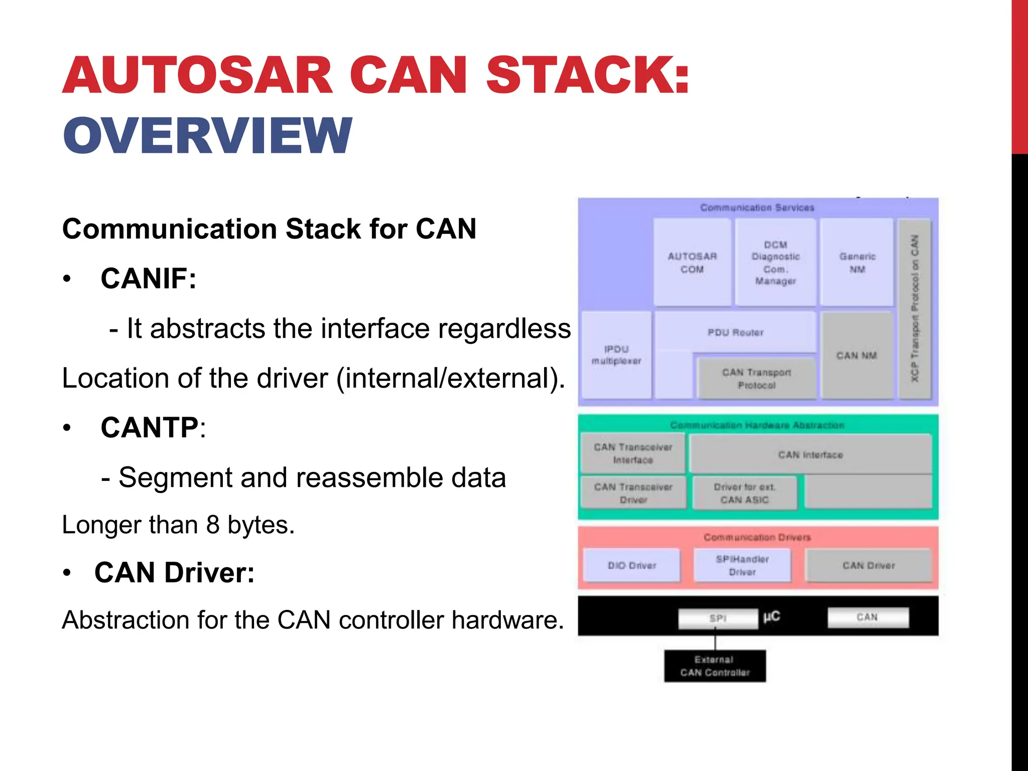
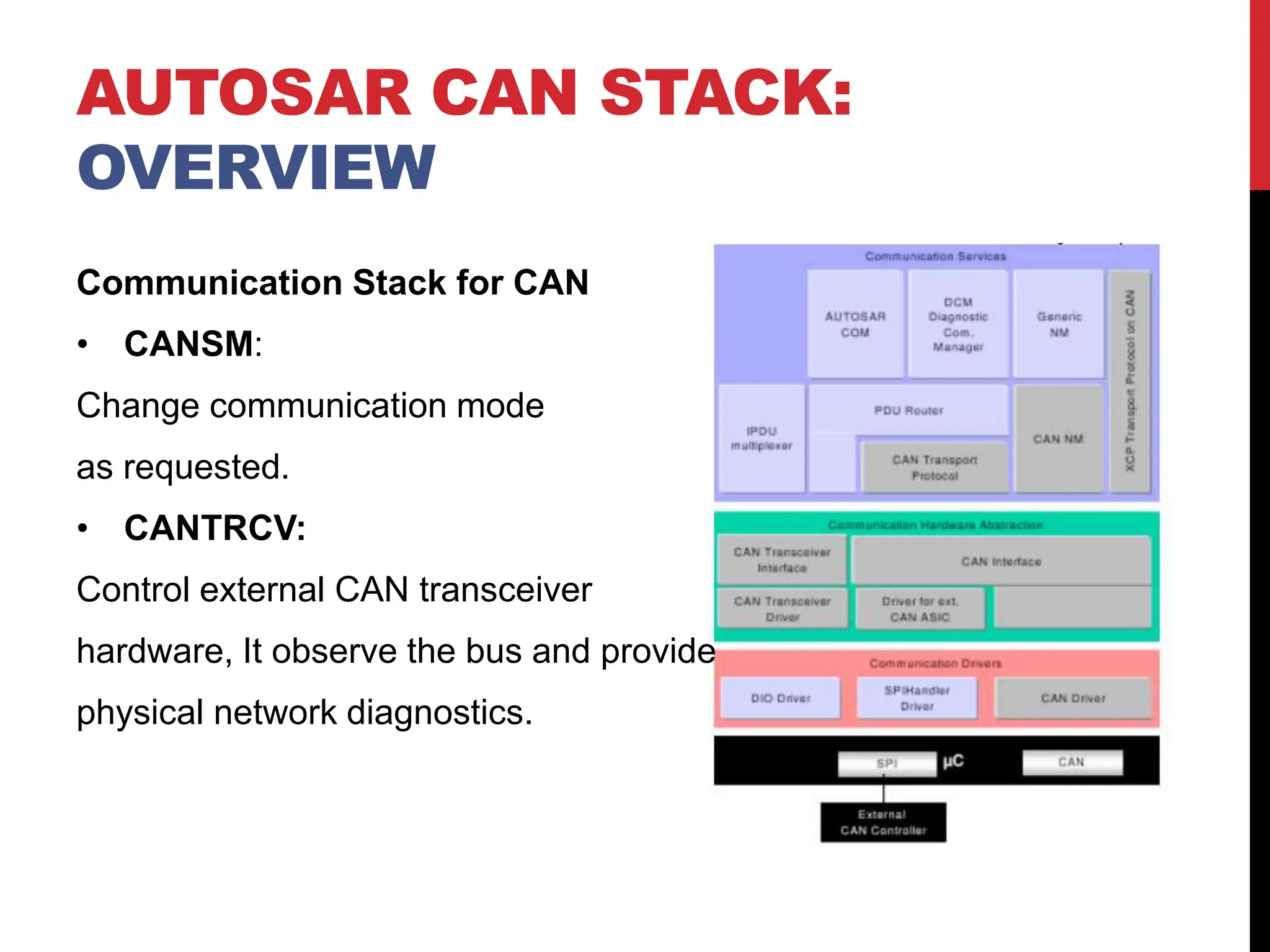
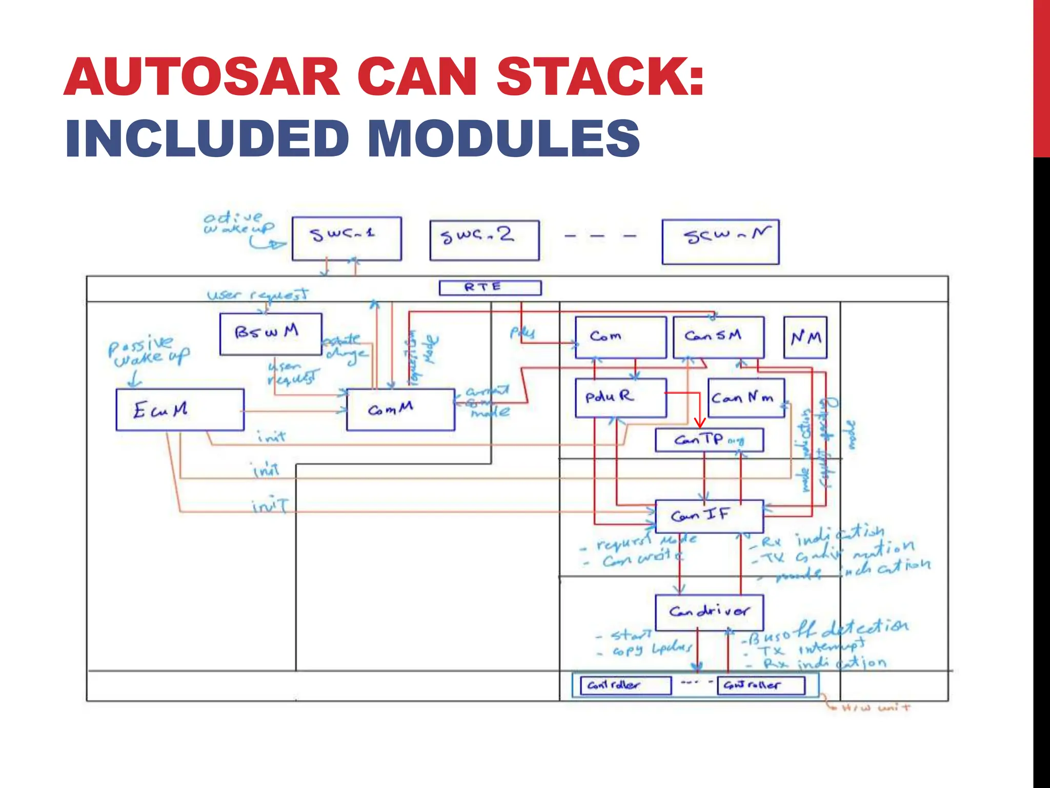
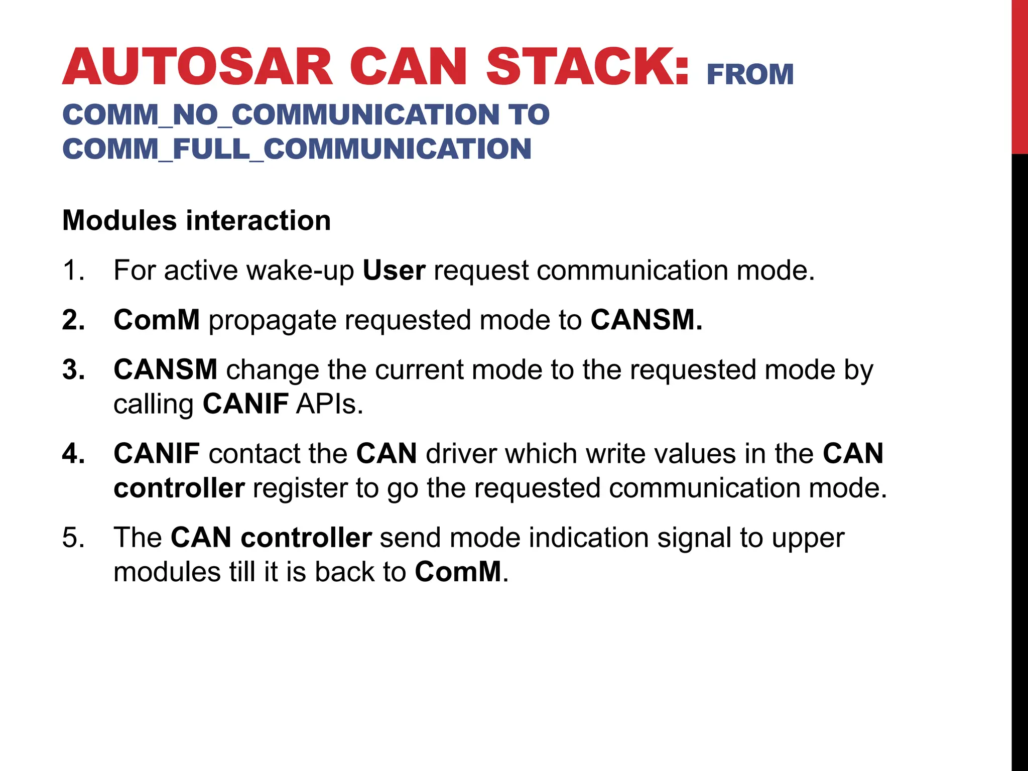
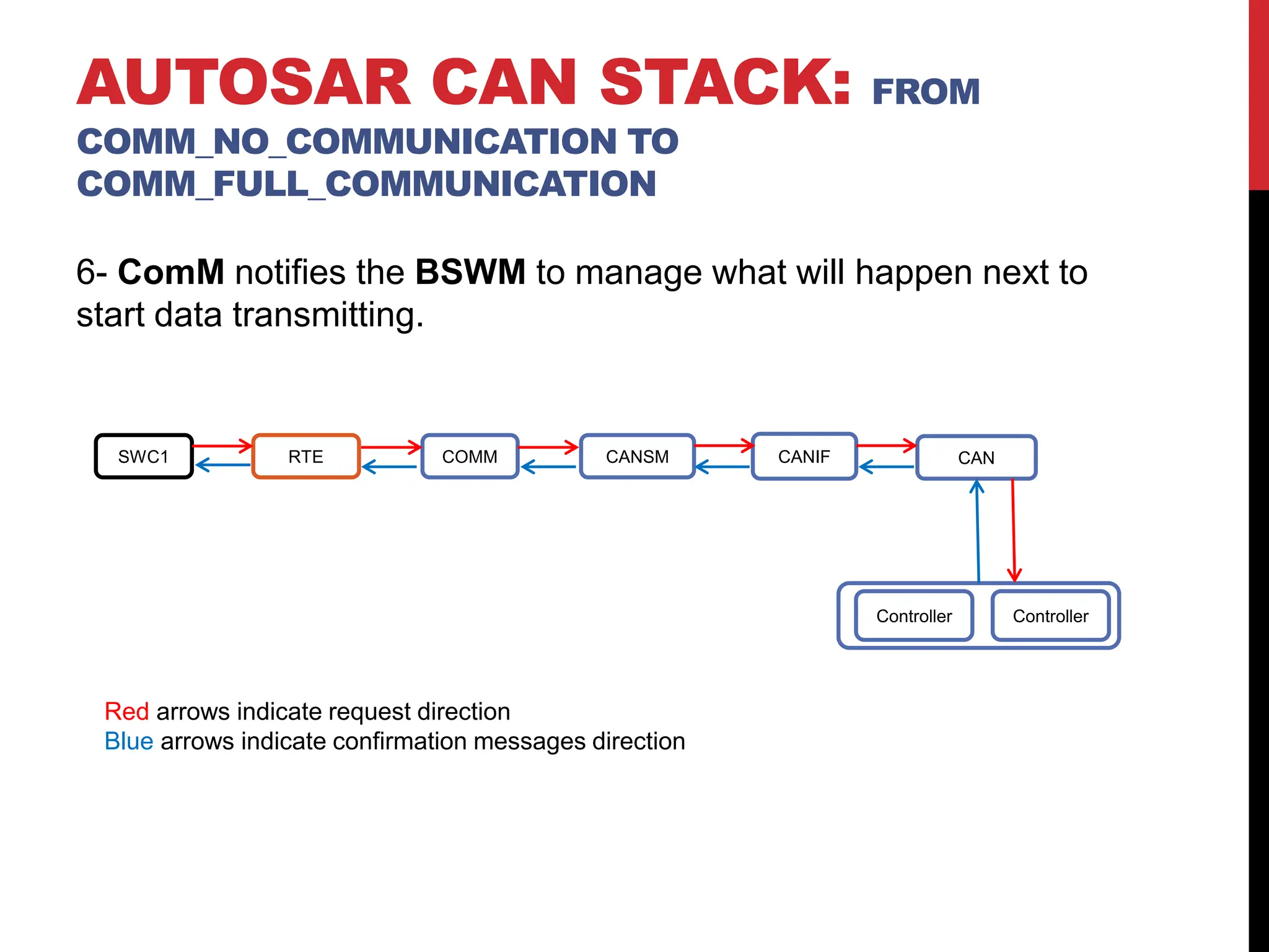
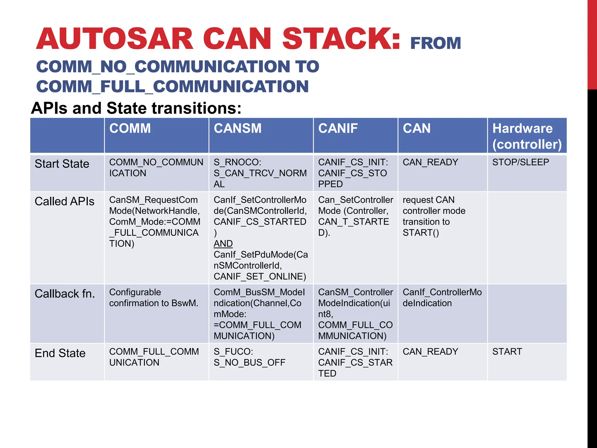
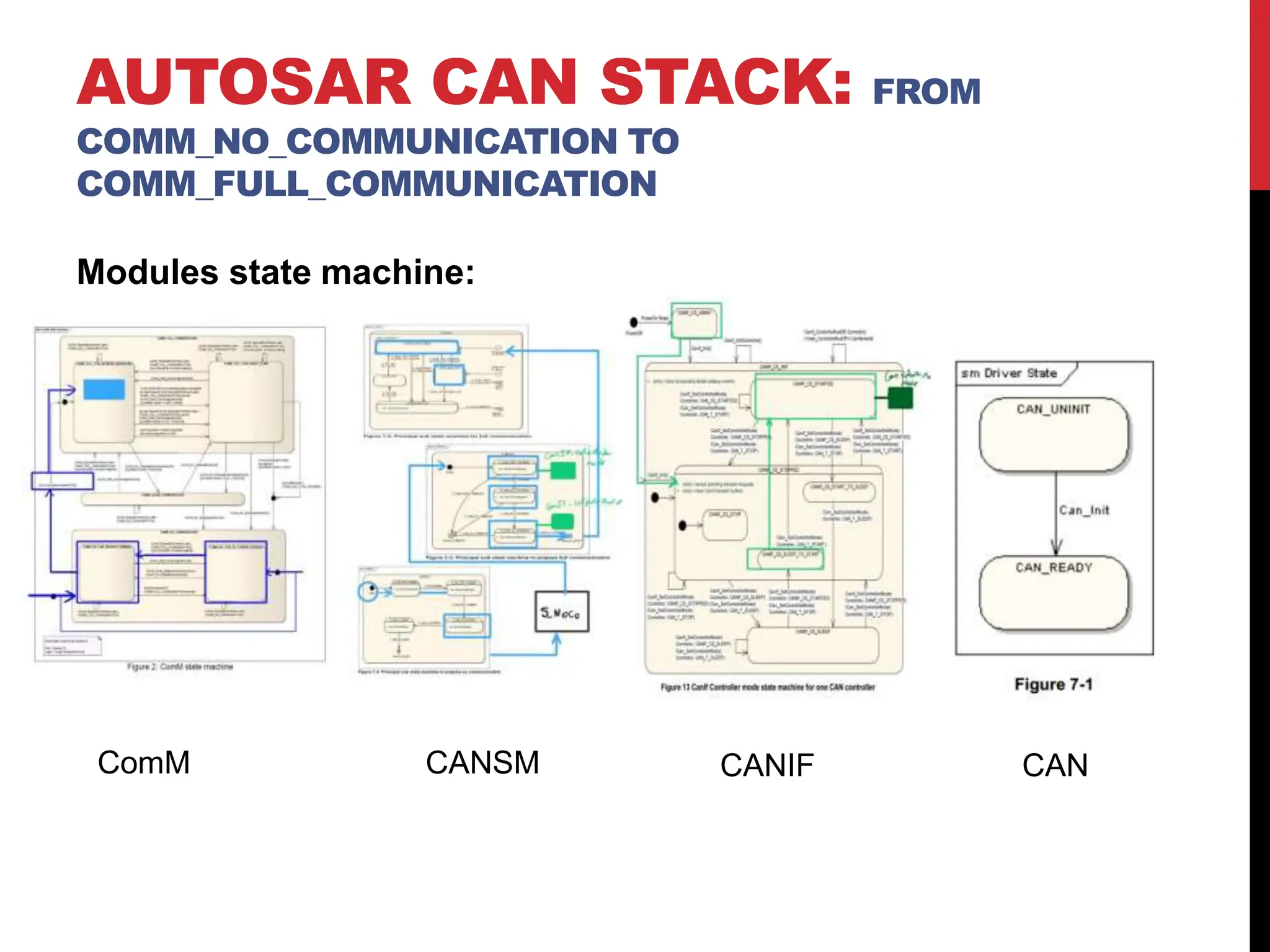
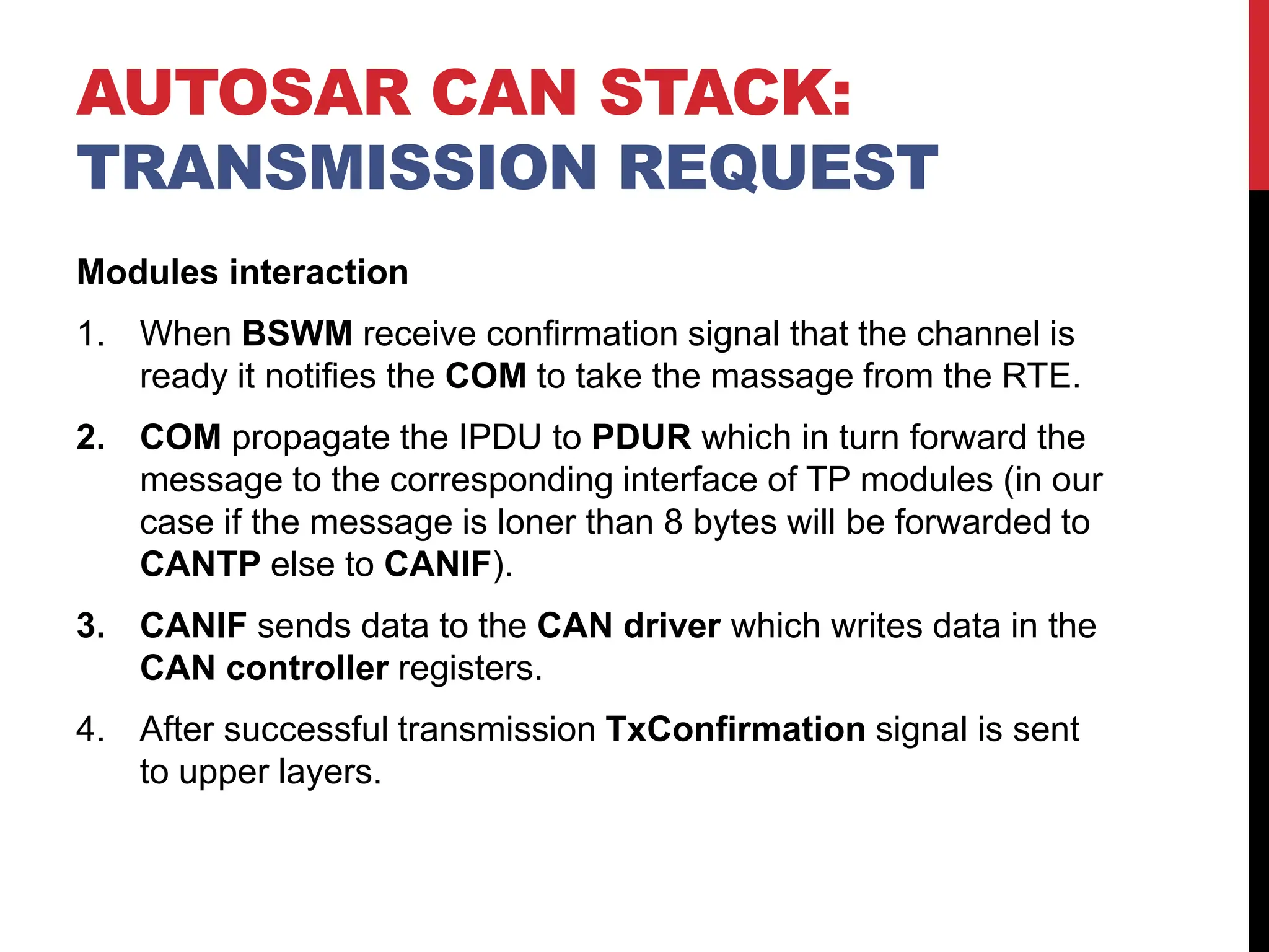
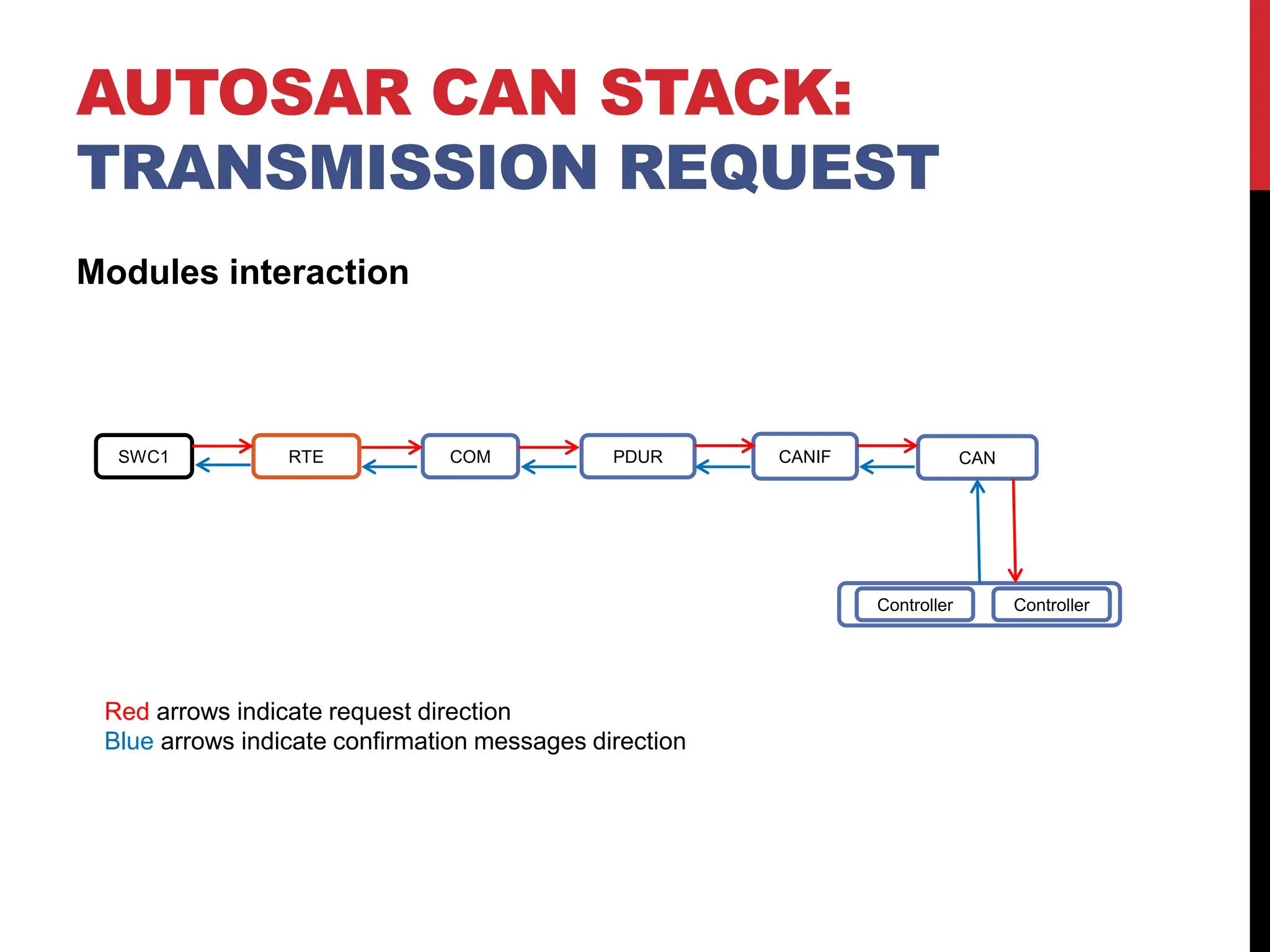
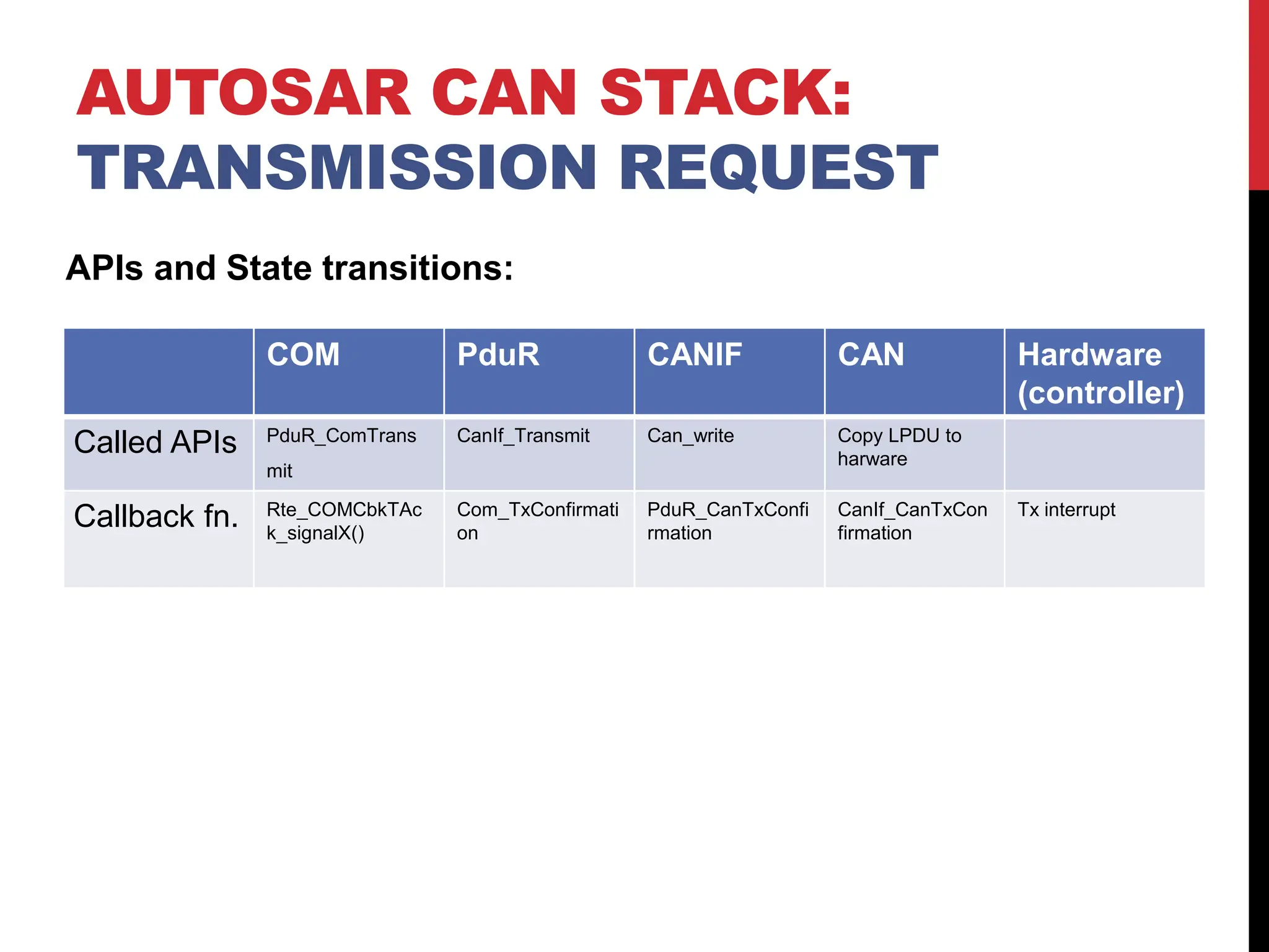
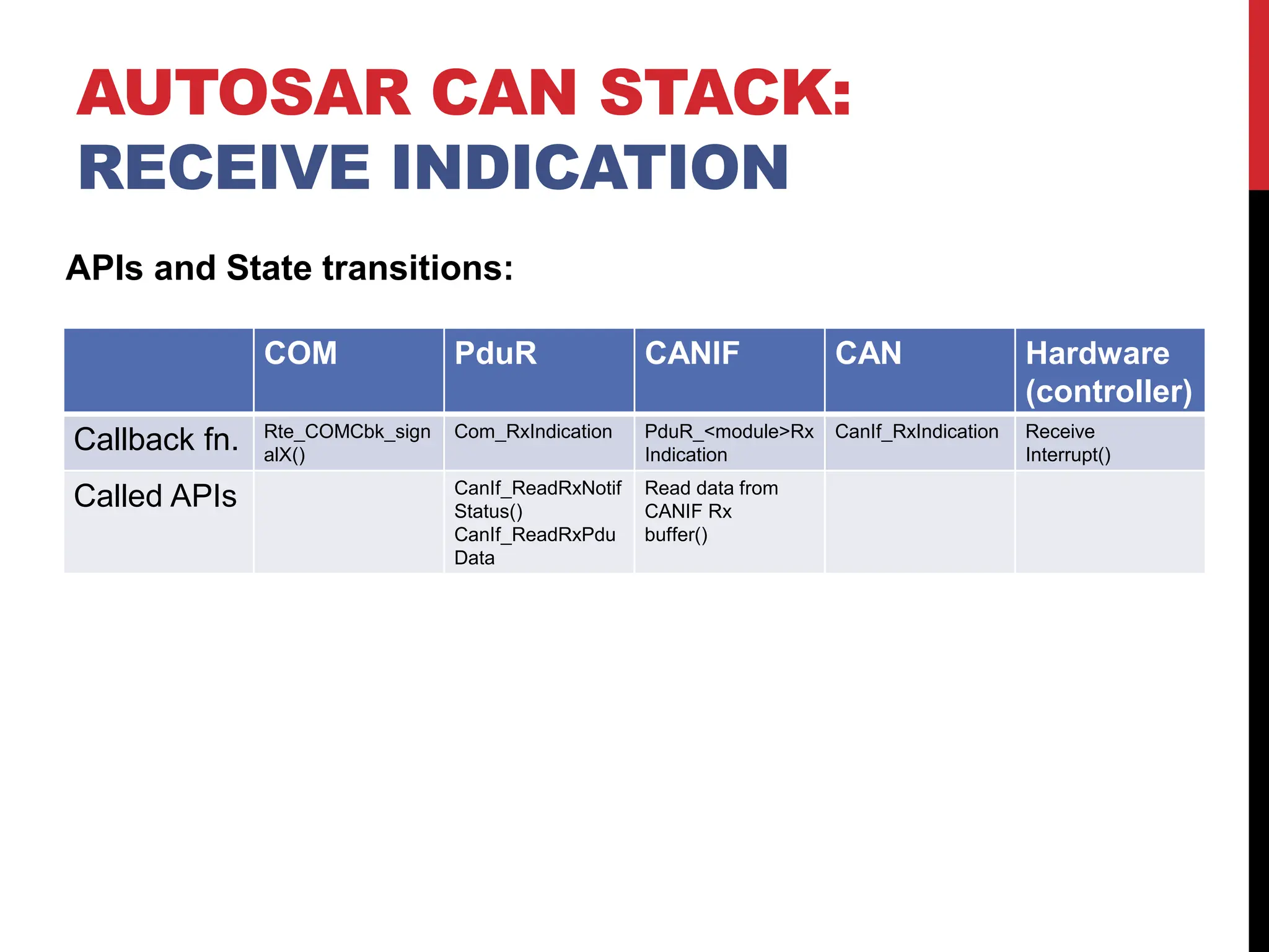
CAN STACK
OVERVIEW
• AUTOSAR CAN Stack
• Overview.
• Included modules.
• From COMM_NO_COMMUNICATION to COMM_FULL_COMMUNICATION.
• Transmission request.
• Receive indication.
AUTOSAR CAN STACK:
OVERVIEW
Autosar VFB
• The integration of functions from different suppliers is established through a virtual
functional bus.
• Allow virtual integration between SW-c as long as communication mechanism is defined.
• Collection of all communication mechanism.
• Interfaces on an abstract level that allow s/w design regardless the target h/w.
RTE
• Realization of VFB for a specific ECU.
• It mange the communication inter/intra ECU.
AUTOSAR CAN STACK:
OVERVIEW
Communication Stack for CAN
• COM:
- Transfer signals from, and to RTE.
- Pass signals to CANTP or PDUR
depending on the used service.
• PDU-Router:
- Route I-PDUs between the following
modules: Communication interface (CANIF),
Transport protocol (CANTP), Diagnostics (DCM)
AUTOSAR CAN STACK:
OVERVIEW
Communication Stack for CAN
• CANIF:
- It abstracts the interface regardless
Location of the driver (internal/external).
• CANTP:
- Segment and reassemble data
Longer than 8 bytes.
• CAN Driver:
Abstraction for the CAN controller hardware.
AUTOSAR CAN STACK:
OVERVIEW
Communication Stack for CAN
• CANSM:
Change communication mode
as requested.
• CANTRCV:
Control external CAN transceiver
hardware, It observe the bus and provide
physical network diagnostics.
AUTOSAR CAN STACK:
OVERVIEW
Included modules from service layer:
• ComM: Propagate requested communication mode to CanSM
• BSWM: Forward user requests to ComM and report
communication state to the user.
• ECUM: Detect passive wake up and initialize related modules.
AUTOSAR CAN STACK:
INCLUDED MODULES
Active VS Passive Wake-up
• Active wake-up: when the current ECU is the source of the
wake-up signal (sensor).
• Passive wake-up: when another ECU is the source of the
wake-up signal. In this case the ECU should receive NM
frames to keep the ECU in the passive wake-up mode.
AUTOSAR CAN STACK: FROM
COMM_NO_COMMUNICATION TO
COMM_FULL_COMMUNICATION
Modules interaction
1. For active wake-up User request communication mode.
2. ComM propagate requested mode to CANSM.
3. CANSM change the current mode to the requested mode by
calling CANIF APIs.
4. CANIF contact the CAN driver which write values in the CAN
controller register to go the requested communication mode.
5. The CAN controller send mode indication signal to upper
modules till it is back to ComM.
AUTOSAR CAN STACK: FROM
COMM_NO_COMMUNICATION TO
COMM_FULL_COMMUNICATION
6- ComM notifies the BSWM to manage what will happen next to
start data transmitting.
AUTOSAR CAN STACK: FROM
COMM_NO_COMMUNICATION TO
COMM_FULL_COMMUNICATION
SWC1 RTE COMM CANSM CANIF CAN
Controller Controller
Red arrows indicate request direction
Blue arrows indicate confirmation messages direction
AUTOSAR CAN STACK: FROM
COMM_NO_COMMUNICATION TO
COMM_FULL_COMMUNICATION
APIs and State transitions:
COMM CANSM CANIF CAN Hardware
(controller)
Start State COMM_NO_COMMUN
ICATION
S_RNOCO:
S_CAN_TRCV_NORM
AL
CANIF_CS_INIT:
CANIF_CS_STO
PPED
CAN_READY STOP/SLEEP
Called APIs CanSM_RequestCom
Mode(NetworkHandle,
ComM_Mode:=COMM
_FULL_COMMUNICA
TION)
CanIf_SetControllerMo
de(CanSMControllerId,
CANIF_CS_STARTED
)
AND
CanIf_SetPduMode(Ca
nSMControllerId,
CANIF_SET_ONLINE)
Can_SetController
Mode (Controller,
CAN_T_STARTE
D).
request CAN
controller mode
transition to
START()
Callback fn. Configurable
confirmation to BswM.
ComM_BusSM_ModeI
ndication(Channel,Co
mMode:
=COMM_FULL_COM
MUNICATION)
CanSM_Controller
ModeIndication(ui
nt8,
COMM_FULL_CO
MMUNICATION)
CanIf_ControllerMo
deIndication
End State COMM_FULL_COMM
UNICATION
S_FUCO:
S_NO_BUS_OFF
CANIF_CS_INIT:
CANIF_CS_STAR
TED
CAN_READY START
AUTOSAR CAN STACK: FROM
COMM_NO_COMMUNICATION TO
COMM_FULL_COMMUNICATION
Modules state machine:
ComM CANSM CANIF CAN
Modules interaction
1. When BSWM receive confirmation signal that the channel is
ready it notifies the COM to take the massage from the RTE.
2. COM propagate the IPDU to PDUR which in turn forward the
message to the corresponding interface of TP modules (in our
case if the message is loner than 8 bytes will be forwarded to
CANTP else to CANIF).
3. CANIF sends data to the CAN driver which writes data in the
CAN controller registers.
4. After successful transmission TxConfirmation signal is sent
to upper layers.
AUTOSAR CAN STACK:
TRANSMISSION REQUEST
Modules interaction
SWC1 RTE COM PDUR CANIF CAN
Controller Controller
Red arrows indicate request direction
Blue arrows indicate confirmation messages direction
AUTOSAR CAN STACK:
TRANSMISSION REQUEST
AUTOSAR CAN STACK:
TRANSMISSION REQUEST
COM PduR CANIF CAN Hardware
(controller)
Called APIs PduR_ComTrans
mit
CanIf_Transmit Can_write Copy LPDU to
harware
Callback fn. Rte_COMCbkTAc
k_signalX()
Com_TxConfirmati
on
PduR_CanTxConfi
rmation
CanIf_CanTxCon
firmation
Tx interrupt
APIs and State transitions:
Modules interaction
To detect received data Interrupt or polling can be used
Interrupt: The controller will notify CANIF when data is received
Polling: CANIF will periodically check weather data is received or
not.
For both modes after the CANIF detects that there is received
data it will notify upper modules to read data.
After reaching the COM the received data will be available to be
called by the RTE when required.
AUTOSAR CAN STACK:
RECEIVE INDICATION
AUTOSAR CAN STACK:
RECEIVE INDICATION
COM PduR CANIF CAN Hardware
(controller)
Callback fn. Rte_COMCbk_sign
alX()
Com_RxIndication PduR_<module>Rx
Indication
CanIf_RxIndication Receive
Interrupt()
Called APIs CanIf_ReadRxNotif
Status()
CanIf_ReadRxPdu
Data
Read data from
CANIF Rx
buffer()
APIs and State transitions:

CAN communicatoin stack,it take me a long time to found it, hope it help

  • 1.
  • 2.
    OVERVIEW • AUTOSAR CANStack • Overview. • Included modules. • From COMM_NO_COMMUNICATION to COMM_FULL_COMMUNICATION. • Transmission request. • Receive indication.
  • 3.
    AUTOSAR CAN STACK: OVERVIEW AutosarVFB • The integration of functions from different suppliers is established through a virtual functional bus. • Allow virtual integration between SW-c as long as communication mechanism is defined. • Collection of all communication mechanism. • Interfaces on an abstract level that allow s/w design regardless the target h/w. RTE • Realization of VFB for a specific ECU. • It mange the communication inter/intra ECU.
  • 4.
    AUTOSAR CAN STACK: OVERVIEW CommunicationStack for CAN • COM: - Transfer signals from, and to RTE. - Pass signals to CANTP or PDUR depending on the used service. • PDU-Router: - Route I-PDUs between the following modules: Communication interface (CANIF), Transport protocol (CANTP), Diagnostics (DCM)
  • 5.
    AUTOSAR CAN STACK: OVERVIEW CommunicationStack for CAN • CANIF: - It abstracts the interface regardless Location of the driver (internal/external). • CANTP: - Segment and reassemble data Longer than 8 bytes. • CAN Driver: Abstraction for the CAN controller hardware.
  • 6.
    AUTOSAR CAN STACK: OVERVIEW CommunicationStack for CAN • CANSM: Change communication mode as requested. • CANTRCV: Control external CAN transceiver hardware, It observe the bus and provide physical network diagnostics.
  • 7.
    AUTOSAR CAN STACK: OVERVIEW Includedmodules from service layer: • ComM: Propagate requested communication mode to CanSM • BSWM: Forward user requests to ComM and report communication state to the user. • ECUM: Detect passive wake up and initialize related modules.
  • 8.
  • 9.
    Active VS PassiveWake-up • Active wake-up: when the current ECU is the source of the wake-up signal (sensor). • Passive wake-up: when another ECU is the source of the wake-up signal. In this case the ECU should receive NM frames to keep the ECU in the passive wake-up mode. AUTOSAR CAN STACK: FROM COMM_NO_COMMUNICATION TO COMM_FULL_COMMUNICATION
  • 10.
    Modules interaction 1. Foractive wake-up User request communication mode. 2. ComM propagate requested mode to CANSM. 3. CANSM change the current mode to the requested mode by calling CANIF APIs. 4. CANIF contact the CAN driver which write values in the CAN controller register to go the requested communication mode. 5. The CAN controller send mode indication signal to upper modules till it is back to ComM. AUTOSAR CAN STACK: FROM COMM_NO_COMMUNICATION TO COMM_FULL_COMMUNICATION
  • 11.
    6- ComM notifiesthe BSWM to manage what will happen next to start data transmitting. AUTOSAR CAN STACK: FROM COMM_NO_COMMUNICATION TO COMM_FULL_COMMUNICATION SWC1 RTE COMM CANSM CANIF CAN Controller Controller Red arrows indicate request direction Blue arrows indicate confirmation messages direction
  • 12.
    AUTOSAR CAN STACK:FROM COMM_NO_COMMUNICATION TO COMM_FULL_COMMUNICATION APIs and State transitions: COMM CANSM CANIF CAN Hardware (controller) Start State COMM_NO_COMMUN ICATION S_RNOCO: S_CAN_TRCV_NORM AL CANIF_CS_INIT: CANIF_CS_STO PPED CAN_READY STOP/SLEEP Called APIs CanSM_RequestCom Mode(NetworkHandle, ComM_Mode:=COMM _FULL_COMMUNICA TION) CanIf_SetControllerMo de(CanSMControllerId, CANIF_CS_STARTED ) AND CanIf_SetPduMode(Ca nSMControllerId, CANIF_SET_ONLINE) Can_SetController Mode (Controller, CAN_T_STARTE D). request CAN controller mode transition to START() Callback fn. Configurable confirmation to BswM. ComM_BusSM_ModeI ndication(Channel,Co mMode: =COMM_FULL_COM MUNICATION) CanSM_Controller ModeIndication(ui nt8, COMM_FULL_CO MMUNICATION) CanIf_ControllerMo deIndication End State COMM_FULL_COMM UNICATION S_FUCO: S_NO_BUS_OFF CANIF_CS_INIT: CANIF_CS_STAR TED CAN_READY START
  • 13.
    AUTOSAR CAN STACK:FROM COMM_NO_COMMUNICATION TO COMM_FULL_COMMUNICATION Modules state machine: ComM CANSM CANIF CAN
  • 14.
    Modules interaction 1. WhenBSWM receive confirmation signal that the channel is ready it notifies the COM to take the massage from the RTE. 2. COM propagate the IPDU to PDUR which in turn forward the message to the corresponding interface of TP modules (in our case if the message is loner than 8 bytes will be forwarded to CANTP else to CANIF). 3. CANIF sends data to the CAN driver which writes data in the CAN controller registers. 4. After successful transmission TxConfirmation signal is sent to upper layers. AUTOSAR CAN STACK: TRANSMISSION REQUEST
  • 15.
    Modules interaction SWC1 RTECOM PDUR CANIF CAN Controller Controller Red arrows indicate request direction Blue arrows indicate confirmation messages direction AUTOSAR CAN STACK: TRANSMISSION REQUEST
  • 16.
    AUTOSAR CAN STACK: TRANSMISSIONREQUEST COM PduR CANIF CAN Hardware (controller) Called APIs PduR_ComTrans mit CanIf_Transmit Can_write Copy LPDU to harware Callback fn. Rte_COMCbkTAc k_signalX() Com_TxConfirmati on PduR_CanTxConfi rmation CanIf_CanTxCon firmation Tx interrupt APIs and State transitions:
  • 17.
    Modules interaction To detectreceived data Interrupt or polling can be used Interrupt: The controller will notify CANIF when data is received Polling: CANIF will periodically check weather data is received or not. For both modes after the CANIF detects that there is received data it will notify upper modules to read data. After reaching the COM the received data will be available to be called by the RTE when required. AUTOSAR CAN STACK: RECEIVE INDICATION
  • 18.
    AUTOSAR CAN STACK: RECEIVEINDICATION COM PduR CANIF CAN Hardware (controller) Callback fn. Rte_COMCbk_sign alX() Com_RxIndication PduR_<module>Rx Indication CanIf_RxIndication Receive Interrupt() Called APIs CanIf_ReadRxNotif Status() CanIf_ReadRxPdu Data Read data from CANIF Rx buffer() APIs and State transitions: