Downloaded 1,247 times


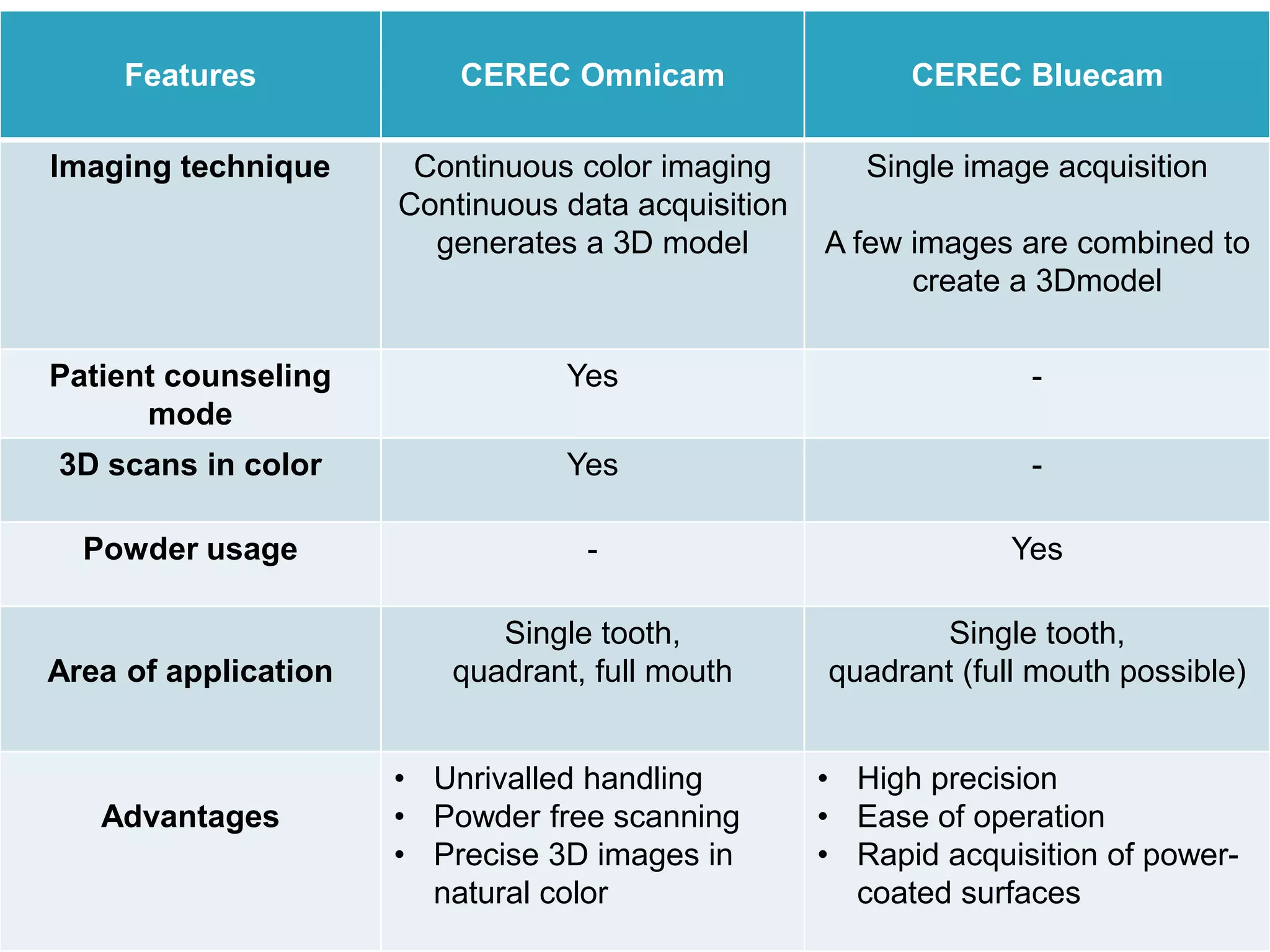


This document discusses CAD CAM dentistry and digital impressions. It begins by comparing traditional dentistry and CAD CAM dentistry, noting advantages of digital impressions like decreased turnaround time, improved accuracy and fewer remakes. It then reviews several studies showing digital impressions are more accurate and comfortable for patients. The document outlines the basic components of CAD CAM systems including scanners, design software and milling machines. It discusses open vs closed architecture systems and chairside vs lab-based production. Recent advances in digital impression technology like powder-free scanning and continuous color imaging are also summarized.


