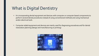
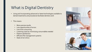
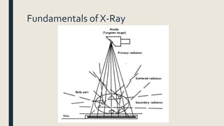
SlideShare a Scribd company logo
1 of 161
INTRODUCTIONTO
DIGITAL DENTISTRY
Prepared by: Eng. IbrahimTayyan
Contents:
ā–  Definition of Digital Dentistry
ā–  Dental Radiography
ā–  Dental CAD/CAM
ā–  Integrating Radiography with CAD/CAM
ā–  Dental Surgical Navigation System
ā–  Computer Assisted Anesthesia System
ā–  Appendix a: Dental Software
ā–  Appendix b: Networking and AdvancedWindows Settings
DEFINITION OF DIGITAL
DENTISTRY
Definition, Uses and Advantages
What is Digital Dentistry
ā€¢ It is incorporating dental equipment and devices with computer or computer based components to
perform several dental procedures instead of using conventional methods and using mechanical
and/or electrical tools
ā€¢ Computer aided equipment and devices are mainly used for diagnosing procedures and for dental
restoration planning (design and manufacturing or printing)
What is Digital Dentistry
ā€¢ Using and incorporating advanced or latest technologies available to
dental treatments and procedures facilitate dentists work
ā€¢ This means:
ā€¢ More precise results
ā€¢ Less opportunities of errors
ā€¢ Less time consuming
ā€¢ Lowering costs by minimizing consumables needed
ā€¢ Patient satisfaction
ā€¢ Efficient file management systems
ā€¢ State of art clinics
What is Digital Dentistry
ā€¢ Major challenges against using digital dentistry:
ā€¢ Expensive capital equipment
ā€¢ Some dentists are unfamiliar with using computers
ā€¢ Learning curve
ā€¢ Dentists and lecturers still sticking on using old traditional
procedures
DENTAL
RADIOGRAPHY
Using X-ray Beam to Produce Images for Diagnostic Uses
Medical Imaging
Medical imaging is the technique and process used to create images of the human body (or parts and
function thereof) for clinical purposes (medical procedures seeking to reveal, diagnose, or examine disease)
or medical science (including the study of normal anatomy and physiology)
Main Categories:
X-Ray Radiography
Ultrasonography
Nuclear Medicine
Magnetic Resonance Imaging
Fundamentals of X-Ray
Electromagnetic waves: Also known as Electromagnetic Radiation is a form of energy waves that have both
an electric and magnetic field and transmit energy and travel through space and vacuum
Fundamentals of X-Ray
X-RayTechnologies for Dentists
ā€¢ Dental X-ray technologies are used to find hidden dental structures, malignant or benign masses, bone
loss, and cavities
ā€¢ A radiographic image is formed by a controlled burst of X-ray radiation which penetrates oral
structures at different levels, depending on varying anatomical densities, before striking the x-ray
detector
ā€¢ Materials or substances with higher densities appear lighter than materials with lower densities due
to radiation penetrates lower densities easier than higher ones (radiopaque)
ā€¢ Teeth appear lighter for example because less radiation penetrates them to reach the detector, while
blood vessels appear darker since radiation penetrates it easily (radiolucency)
ā€¢ X-ray have properties of penetration, absorption, scattering, ionization and attenuation, but they
cannot be reflected, refracted nor deflected by magnetic or electrical field
History of X-Ray and its Usage in Dentistry
ā€¢ Wilhelm Conrad Rƶntgen a German mechanical engineer and
physicist discovered and produced x-ray on 8th of November 1895
ā€¢ Max Gebbert a German mechanic and a co-founder of the
company Reiniger, Gebbert & Schall (RGS) met withWilhelm
Rƶntgen only after 3 days of x-ray discovery
ā€¢ Few months later, RGS produced the first commercial intraoral x-
ray in history
ā€¢ In 1934, Siemens-Reiniger-Werke (SRW) brought the famous
"RoĢˆntgenkugel" X- ray sphere onto the market and at the time it
was the smallest X-ray device in the world
History of X-Ray and its Usage in Dentistry
ā€¢ In 1961, the first OPG system was commercially produced named
Panorex OPG
ā€¢ In 1995, the OPG system has been digitalized for the first time and
it was named DXIS
ā€¢ In 1996, the first CBCT has been introduced and was named
Newtom 3000
Types of Dental Radiographs
Intraoral Imaging Extraoral Imaging
Intraoral Imaging
ā€¢ Intraoral imaging as the name indicates, is taking images of the teeth while the x-ray detector is inside
the patientā€™s mouth
ā–  Missing teeth
ā–  Impacted teeth
ā–  Dental caries
ā–  Periodontal disease
ā–  Tooth abnormalities
ā–  Retained roots
ā–  Cysts and tumors
ā–  Tooth Structure
ā–  Supporting Bone
Main Indications of intraoral imaging:
Types of Intraoral ImagesViews
Periapical Bitewing Occlusal
Intraoral Imaging
PeriapicalView is the most widely used imaging view.
It shows the whole tooth, from the crown to beyond the end of the root to where the tooth is
anchored in the jaw.
ā€¢ Detect apical inflammation/ infection including
cystic changes
ā€¢ Assess periodontal problems
ā€¢ Trauma-fractures to tooth and/or surrounding
bone
ā€¢ Pre/ post apical surgery/extraction..
ā€¢ Detect any presence or position of unerupted
teeth
ā€¢ Endodontics root canal treatment.
ā€¢ Evaluation of implants.
Main Indications of Periapical Imaging:
Intraoral Imaging
Bitewing View show details of the upper and lower teeth in one area of the mouth. Each bite-wing
shows a tooth from its crown to about the level of the supporting bone
Bite-wing X-rays are used to detect decay between teeth and changes in bone density caused by gum
disease.They are also useful in determining the proper fit of a crown (or cast restoration) and the
marginal integrity of fillings.This type of X-ray shows the dentist how these teeth touch one another
(or occlude)
Intraoral Imaging
OcclusalView offers a clear view of the floor of the mouth to show the bite of the upper or lower
jaw.This kind of X-ray highlights childrenā€™s tooth development to show the primary (baby) and
permanent (adult) teeth
Intraoral X-ray Models
Intraoral X-ray Components
Extension arm
PID or cone
Exposure
Switch
Control Panel
X-rayTube Housing
Intraoral X-ray Components
Extension Arm: The dentist adjust the arm by extending it and changing the position of it to place it
near the patientā€™s cheek to take an image for region of interest
Intraoral X-ray Components
X-ray tube is in housed inside its housing cover Housing cover with PID
Intraoral X-ray Components
Used to set the patient size, the exposure
time and kVp for some machines
Keep pressing on this button to release exposure
to the patient in terms of milli seconds
Intraoral X-ray Components
Factors Affecting X-ray Beam
ā€¢ Focal Spot
ā€¢ Collimation
ā€¢ Filtration
ā€¢ kVp
ā€¢ mA
ā€¢ Time Exposure
Factors Affecting X-ray Beam
ā€¢ Focal Spot is the small region or spot in the anode where the electrons hit the region to produce x-
ray photons
ā€¢ Smaller focal spots give better image quality and increased sharpness, while larger focal spots
produce blurring in the image
Factors Affecting X-ray Beam
ā€¢ Collimator: it is a device that is used to regulate the size of the beam leaving the x-ray tube and
strict it to a smaller beneficial size and necessary area
ā€¢ PID: also known as position indicating device aids in collimation and guides the direction of the x-
ray beam which improves and standardizes dental radiographic imaging and reduces the patient's
risk of radiation exposure
Factors Affecting X-ray Beam
ā€¢ An Aluminum disk is placed between the collimator and the exiting window of the x-ray tube, to
absorb unnecessary x-ray wavelengths (weak long wavelength rays)
Factors Affecting X-ray Beam
ā€¢ There are two types of filtrations:
1. Inherent Filtration: filters that are components of the x-ray tube (tube wall, insulating oil, inner
aluminum disks and other inside components)
2. Added Filtration: filters that are added to the x-ray tube to meet safety standards
ā€¢ Total Filtration is the sum of inherent and added filtrations and it should not be less than 2.5 mmAl
ā€¢ Collimation, filtration and focal spot play an important role in limiting unnecessary x-ray beams
to reach the body, therefore reduces risk of unhealthy conditions and makes the image sharper
and better and eliminating blurring
Factors Affecting X-ray Beam
ā€¢ Kilovolt power or peak voltage: controls the force that attracts electrons to anode
ā€¢ As kVp increases, the penetration power of the x-ray beam increases, so it penetrates denser
tissues but the contrast of the image decreases
ā€¢ Contrast: is the difference in luminance, hue or color that makes an image distinguishable
Factors Affecting X-ray Beam
ā€¢ Milliampere: It is the current passing through the tungsten filament to produce electrons
ā€¢ Raising the mA raises the heating of the coil, which means more x-ray photons are produced and
emitted and therefore increases the darkness of the image
Factors Affecting X-ray Beam
ā€¢ PeakVoltage is also known as controlling the quality of x-ray beam
ā€¢ Milliamperage is also known as controlling the quantity of x-ray beam
ā€¢ Also the distance between the x-ray source and the object plays role in the intensity of the image
ACVs DC X-Ray Machines
X-Ray Machines
ā€¢ DC X-ray machines are slightly better than AC in terms of safety for the patient, since less
radiation is exposed and radiation released is mostly useful ones
ā€¢ In terms of image quality, there are no proven studies that DC is better nor vice versa
ā€¢ KVP used in intraoral x-ray: normally fixed at 70 kVp or 60 kVp with some machines you can
choose either 60 or 70 kVp.
ā€¢ mA used in intraoral x-ray: normally fixed at 3.5, 7 or 8 mA
ā€¢ Focal Spot used in x-rays is usually 0.4 or 0.5 mm
X-ray Detectors
X-ray Films Direct Digital Imaging:
Intraoral Sensors
Indirect Digital Imaging: PSP
Imaging
X-ray Films
ā€¢ When using traditional film, X-rays interact with a layer on the film called the film emulsion, which
contains silver halide crystals that absorb the radiation.The crystals produce a latent image of a tooth
and its surrounding structures, which becomes a visible image once the film is chemically processed.
X-ray Films
Examples of Artifact Errors for Films
Double Image: 2 times exposure on
same film at different regions
Bended film Black line due to bended film
Examples of Artifact Errors for Films
Wave like lines due to directing
the X-ray through the lead foil side
of the film back (Reversed Film)
Black spots: Developer contamination
before immersion into the developer
solution
Scratched Film
Examples of Artifact Errors for Films
White Spots: Contamination with fixer
before processing
Smudge: Finger Prints
Examples of Artifact Errors for Films
PSP Imaging
ā€¢ PSP (photostimulable phosphor plate) is a cordless plate that is similar in shape and concept to
conventional x-ray films but differs in method of interpreting absorbed radiation to a readable image
ā€¢ X-ray films are processed by chemicals called fixer and developers inside a manual or automatic film
processor, while PSPs are integrated to a PC via PSP scanner
ā€¢ Photostimulable phosphor has the special property of storing the X-ray energy in a latent form and
releasing the same when stimulated by a laser energy in the scanner. Unlike x-ray films where the
stored latent image is visible by chemical processing
PSP Imaging
PSP ImagingWorkflow
PSP ImagingWorkflow
PSP ImagingWorkflow
PSP ImagingWorkflow
PSP ImagingWorkflow
PSP ImagingWorkflow
ā€¢ Stimulation with a scanning laser beam at a wavelength of 660 nm releases
electrons and then electrons will emit light at a wavelength of around 390 nm
ā€¢ The PSP is simply moved in front of a fixed laser source.The laser beam is
deflected by mirrors onto the surface of the PSP
ā€¢ After processing is complete, the scanner then erases the plate for reuse
PSP ImagingWorkflow
PSP Imaging
ā€¢ Displaying an image on a PC is much better than displaying it on printed films on an x-ray viewer
ā€¢ You can manipulate the image, by changing the brightness and contrast, and you can do several
post enhancements on the image such as changing the sharpness, smoothness, inverting B/W,
colorize and even do some extra advanced filters so the image appears better
ā€¢ You can also save patientsā€™ data and manage files for all patients on the software easily
PSP Imaging
ā€¢ Using PSP instead of film solved many of the films drawbacks but not all of them
ā€¢ For example it has solved the errors due to contamination and misuse of chemicals, in addition to
lowering costs by eliminating the use of chemicals that costs some money every day
ā€¢ However, it did not solve the errors issue due to mishandling of the phosphor plate, such as
scratches and smudge
Intraoral Sensors
ā€¢ Using intraoral sensors, image will directly appear on the PC monitor after exposure has been taken with
less than 2 seconds (depending on computerā€™s speed)
Intraoral Sensors
Intraoral SensorsTypes
Wired Sensors Wireless Sensors
ā€¢ Direct USB 2.0
ā€¢ USB 2.0 cable + interface
ā€¢ Ethernet
ā€¢ RF wireless
ā€¢ Bluetooth
ā€¢ WiFi System
Intraoral Sensors
ā€¢ Wired Sensors are used much more than wireless ones due to speed, no interruption, less expensive
and no noise artifact due to electromagnetic waves interference (such interference is widely seen in
RF ones)
ā€¢ Regardless of sensorā€™s types, all of the intraoral sensors need 80% less radiation than conventional x-
ray films, which means much safer for the patient and the dentist
ā€¢ You no need to retake exposure if the image obtained is of bad brightness, contrast and sharpness
unlike x-ray films.
ā€¢ Sensors helped the endodontics a lot in endo treatment procedures, since along with apex locator
could easily take exposures during operation without the need to stop working till the film is
processed.Also the endodontic could easily take several continuous shots since image transferring
and displaying is much faster in addition to much more reduced exposure to the patient
Intraoral Sensors
Intraoral Sensors
Scintillator:Converts X-ray to light
Photodiodes: Convert light to
electrons
Integrated Circuit (CCD or CMOS)
X-ray Photons
Light
Electrons
Readable Data
Intraoral Sensors
ā€¢ CMOS (complementary metal oxide semiconductor) and CCD (charge coupled device) image sensors
are two different technologies used for capturing images digitally
ā€¢ Both types of imager sensors can convert light into electric charge and process it into electronic
signals
ā€¢ Imaging sensors layers are integrated circuits for converting light into electronic signals
ā€¢ In the case of a CCD sensor, every pixelā€™s charge is transferred through an extremely reduced
number of output nodes (often just one) to be converted to voltage, buffered, and sent off-chip as
an analog signal.
ā€¢ In the case of a CMOS sensor, each pixel comes with its own charge-to-voltage
conversion, and the sensor often also features digitization circuits, amplifiers, and noise-
correction, so that the chip can output digital bits
Intraoral Sensors
Intraoral Sensors
Intraoral Sensors
ā€¢ CCD sensors create high quality images with low noise (grain).They are more sensitive to light.
However, CCD sensors consume around 100 times more power than equivalent CMOS sensors.
ā€¢ However, intraoral sensors use CMOS-APS technique instead of CCD despiteCCD has lower noise
interference than CMOS, due to the fact that if one pixel in a row is defected, all of the row gets that
defect plus it has a higher speed than CCD.
ā€¢ CMOS manufacturing costs are less than
CCD
Intraoral Sensors
ā€¢ Sensors in general comes in 2 or 3 different sizes
ā€¢ Size 1 is the most used size as a standard universal size
for all patients
ā€¢ Size 2 is used for bitewing imaging
ā€¢ Not all sensor companies has size 0 (pediatrics)
Factors Affecting the Image Quality
ā€¢ Grayscale, bit depth or dynamic range: it is the scale representing the range of gray color range,
measured in bits.
ā€¢ Grayscale of 8 bit = 2^8 colors or shades
ā€¢ 16 bit is the latest available in market which means 65536 colors
Factors Affecting the Image Quality
ā€¢ Spatial resolution is quantified in the number of line pairs that can be distinguished per millimeter (lp/mm).A
line pair consists of a dark line and a bright line. So if one line is 5 microns wide, then a line pair will be 10
microns wide and there would be 1 mm/10 microns = 100 line pairs per millimeter.
ā€¢ Spatial resolution is a measure of the smallest object that can be resolved by the sensor. It is a
measure of the accuracy or detail of a graphic display
Factors Affecting the Image Quality
ā€¢ A pixel is the smallest unit of a digital image or graphic that can be displayed and represented on a digital
display device
ā€¢ Each pixel has a unique logical address, a size of eight or 16 bits
ā€¢ The smaller the pixel size, the better the image resolution and quality are
Factors Affecting the Image Quality
ā€¢ CMOS-APS with CsI Sensor
ā€¢ Bit Depth: 16 bits
ā€¢ Theoretical resolution: 33.3 lp/mm
ā€¢ Measured resolution: 28 lp/mm
ā€¢ Pixel size at capture: 15 Ī¼m
ā€¢ Gold inner cables instead of copper (more ductile and
can bear bending better)
ā€¢ Replaceable Sensor cable
The highest quality available in the market has the following specifications:
Full Mouth Series Survey
Intraoral Sensor Pros
ā€¢ No consumable costs at all (except for disposable sheath that costs around 100 fils)
ā€¢ Much better resolution than x-ray films
ā€¢ Rigid and robust. No errors due to bending nor scratch or even finger prints
ā€¢ Long life time: not less than 500,000 exposures
Drawbacks of Intraoral Sensors
ā€¢ Typically more expensive than x-ray films (Sensor may cost 2000 to 4500 JDs while x-ray films are
less than 80 JDs)
ā€¢ Care must be taken when handling the sensor:
1. The cable could get cutoff due to excessive bending and kinking
2. The STRAIN RELIEF is a critical component, where the cable could be broken
3. Most of the sensors available in the market are not cable replaceable (if the cable breaks down, you have
to exchange the whole sensor)
4. In case of models where sensor is a USB built-in cable (the one where interface is not needed), cable can
easily be defected due to computer port issues and in this case you have to pay to exchange the whole
system
ComparisonTable
No Description Film Based PSP Sensor
1 Image Acquisition Indirect Indirect Direct
2 Radiation Dose High Medium Low
3 Image Process Chemicals Scanner and PC PC
4 Time to Process Few minutes Less than one minute Less than 2 seconds
5 Post Enhancement None Wide range Wide range
6 Life Span Single Use Unlimited Use Around 500,000 images
7 Output Hard Copy Soft and Hard Copies Soft and Hard Copies
8 Best Environment None Large Center Small to medium size centers
Techniques for Exposing Radiographs
ā€¢ To obtain accurate and optimum image quality, the correct positioning of the x-ray detector
towards the x-ray cone is essential
ā€¢ There are two used methods for positioning the x-ray
1. ParallelTechnique:The most widely used technique, where the receptor or detector is parallel
to the center tooth axis or perpendicular to the x-ray beam
2. Bisecting Angle: The X-ray beam is perpendicular to an imaginary bisecting angle formed by the
plane of the receptor and the central axis of the tooth
Examples of Bad Positioning
Cone Cutting: Cone not positioned toward the
receptor well
XCP Positioners
ā€¢ These are positioners where the sensor or film is attached to it for precise parallel technique positioning
ā€¢ They are color coded depending on region to be used
ā€¢ Not all dentists use them due to being not that comfortable at setting up
Extraoral Radiography
ā€¢ Extraoral Imaging (in contrast to intraoral): is taking image of the teeth,TMJ, sinus or maxillofacial
regions while the receptor is outside the mouth
Panoramic Radiography
Cephalometric Imaging
CBCT Imaging
Panoramic Radiography
ā€¢ Panoramic imaging (aka orthopantomography) is a technique for producing a single image of the facial
structures that includes both the maxillary and the mandibular dental arches and their supporting
structures using focal plane tomography technique
ā€¢ Tomography is a two-dimensional image of a slice or section through a three-dimensional object.
ā€¢ Focal plane tomography is one type of tomography techniques available in imaging in general
ā€¢ This type is proceeded by imaging a single plane, or slice, of an object) by simultaneously moving the X-
ray generator and X-ray detector so as to keep a consistent exposure of only the plane of interest during
image acquisition
Panoramic Radiography Principle
X-rayTube and
Generator
X-ray Detector (Film
Cassette or 2D sensor)
The patient stands between the x-ray
tube and the detector to take a
tomography for the region of interest
(full mouth)
Panoramic Radiography Principle
The x-ray source and receptor, both are
attached on a rotating disk, while the
patient is positioned under the circular ring
on the center of the disk
This image illustrates how the disk or ring is rotated and how
the beam is exposed towards the receptor, with the direction of
the collimator opening
Panoramic Radiography Principle
These 2 figures show the direction of the continuous x-ray
beam from its starting point (usually the right side of the
patient) and moves from behind his head while the receptor is
facing him till it reaches its end point
Panoramic Radiography Principle
ā€¢ Depending on whether you are using x-ray film cassette or an imaging sensor (CCD or CMOS), the image
will appear as below
ā€¢ Measurements of lengths are never accurate for panoramic images as the image is normally not 1:1 due
to the nature of tomography procedure.
ā€¢ Image size ratio for most panoramic machines is 1:1.19 with option of magnifying up to 25%
Panoramic Radiography Indications
ā€¢ Impacted wisdom teeth diagnosis and treatment planning
ā€¢ Periodontal bone loss and periapical involvement.
ā€¢ Finding the source of dental pain, and when carrying out tooth-by-tooth diagnosis
ā€¢ Assessment for the placement of dental implants
ā€¢ Diagnosis, and pre- and post-surgical assessment of oral and maxillofacial trauma
ā€¢ Temporomandibular joint dysfunctions and ankylosis.
ā€¢ Diagnosis, and pre- and post-surgical assessment of oral and maxillofacial trauma
Panoramic Radiography Indications
ā€¢ Impacted wisdom teeth diagnosis and treatment planning
ā€¢ Periodontal bone loss and periapical involvement.
ā€¢ Finding the source of dental pain, and when carrying out tooth-by-tooth diagnosis
ā€¢ Assessment for the placement of dental implants
ā€¢ Diagnosis, and pre- and post-surgical assessment of oral and maxillofacial trauma
ā€¢ Temporomandibular joint dysfunctions and ankylosis.
ā€¢ Targeted dentists: General dentistry, pediatrics, implantologists, periodontists, maxillofacial surgeons,
radiologists and sometimes ENT
ā€¢ Panorama is rarely used by endodontics as 2D panoramic image does not give a detailed image of the
root canals like the intraoral ones
Panoramic Radiography
Paranasal Sinus
Panoramic Radiography
ā€¢ There are two types of x-ray detectors used in panoramic machines: Cassettes or digital sensors
ā€¢ Imaging companies no longer produce analog cassette types as it takes much more radiation than digital
ones, in addition to the companies movement towards using CBCTs instead of 2D panoramic machines
Image Quality Factors:
ā€¢ Focal Spot: lower focal spots give better sharpness (0.5mm)
ā€¢ Collimation: Reduces secondary radiation
ā€¢ Filtration: Again 2.5 mm Al
ā€¢ kV: Range used is typically from 60 ā€“ 90 kV
ā€¢ mA: Range available is from 3 ā€“ 16 mA
ā€¢ Pixel Size: The best machine available has a pixel size of 27 um
ā€¢ Bit Depth: There is no higher than 16 bit
ā€¢ SensorType: Most sensors are CCD instead of CMOS due to less noise
interreference and lower manufacturing costs. However, CMOS is also
available
ā€¢ Calibration: Do calibration of sensor and diaphragm where necessary
How toTake an Image:
ā€¢ For obtaining a good quality image, the way of positioning the patient in the panoramic machine is totally
essential to reduce white shadows (radiopacity artifacts) or black shadows (radiolucency artifacts) on
regions that are really not radiopaque nor radiolucent which causes diagnosis errors
ā€¢ Also choosing the correct factors (kV and mA) gives an optimum image based on penetration and
brightness of different tissues according to patientā€™s sizes
ā€¢ However, there are setting presets for each patient size and
buttons are located on the control panel
How toTake an Image:
Technologies for Enhancing Image Quality:
ā€¢ As it is seen in this photo, there is a white
vertical shadow in the middle of the image,
where the roots of the anterior teeth are not
that clear
ā€¢ This shadow in the middle is an artifact appeared
from the spine of the patient
ā€¢ Companies have their own techniques to reduce
this white shadow or even removing it
completely
Technologies for Enhancing Image Quality:
At this point the x-ray KV is raised to
maximum value (90 KV) then it goes
back to normal chosen value
ā€¢ Some companies for example, the machine itself
automatically raises up the kilovolt value up to its
maximum once it reaches the midpoint of the teeth,
then the kilovolt value returns back to the value the
personnel has chosen
ā€¢ Other companies raise the milliampere value instead of
the kilovolt, but this gives extra unwanted dose to the
patient, and the image is not as good as using the
kilovolt raising technology
ā€¢ Raising the voltage to maximum will increase the
penetration power of the beam in a way that the spine
will not appear on the display monitor
Technologies for Enhancing Image Quality:
ā€¢ Sometimes the image appears as in this photo
due to the movement of the patientā€™s head.
ā€¢ During panoramic exposures, you have to make
sure that the patient stands still for around 20
seconds, as radiation time is around 14.1
seconds for standard panoramic programs
ā€¢ Some companies to make sure that the head is not
moving, they use some special head temples or other
techniques to make the head stand still
Head temples
Technologies for Enhancing Image Quality:
ā€¢ There is a new technology called direct conversion where the x-ray photons are directly converted to
electronic signals instead of light where Cadmium telluride (CdTe) is used as an x-ray detector (flat panel
detectors)
Technologies for Enhancing Image Quality:
Positioning Errors Example:
Pediatric Image:
Cephalometry:
Cephalometry: is the study and measurement of the head using radiography
Cephalometric analysis is used in dentistry, and especially in orthodontics, to gauge the size and spatial
relationships of the teeth, jaws, and cranium
Cephalometry:
ā€¢ There is no machine that is used only for ceph imaging
ā€¢ There is an additional arm that is attached to some
panoramic models as in the photos
ā€¢ There are machines where you use the same sensor of
panoramic mode for ceph mode by removing the sensor
from the panorama machine to the ceph arm
Detachable Sensor
ā€¢ Other machines use two sensors together,
one for pan and the other for ceph
ā€¢ Unlike pan mode, the tube does not rotate
ā€¢ Both sensor and tube translate in a straight
line direction
CBCT:
ā€¢ Dental cone beam computed tomography (CT) is a special type of x-ray equipment used when regular
dental or facial x-rays are not sufficient.Your doctor may use this technology to produce three dimensional
(3-D) images of your teeth, soft tissues, nerve pathways and bone in a single scan
ā€¢ It is similar to conventional CT scans in main principle but has some differences in the method of projecting
the x-ray beam
CBCTVs CT Scan:
CBCTVs CT Scan:
CBCT Principle:
CBCT Image Reconstruction:
CBCT Images:
ā€¢ Normally, you will have 5 different views
for any image you take
ā€¢ The 3D model does not have any medical
indication as it is used for demonstration
uses only
ā€¢ The 2D panorama is created as a result of
adjusting the jaw line of the 3 anatomical
planes
ā€¢ However, some dentists use it to check
the bone and tissue thicknesses
CBCT ImageAnatomical Planes:
ā€¢ Axial plane is widely used by endodontics to view the canals paths
ā€¢ Coronal plane is used for maxillofacial treatments
ā€¢ Sagittal plane could be used for nerve locating
CBCT Uses:
CBCT Extra Modules
Implant Planning: By navigating the slices on a certain plane, you can trace the nerve location on the left or
right of the mandibular, in order to locate the implant with specific diameters and angulation in order to fit easily
and correctly on its position without hitting the nerve nor hitting the nearby teeth
CBCT Extra Modules
Endo Planning: Endodontics can also plan for endo files interments and apex locating planning
CBCT Extra Modules
Surgical Guides Designing: Implantologist can also design implant stents and mill it on a CAD/CAM milling
machine or a 3D printer to eliminate human errors while inserting the implant
CBCT Extra Modules
Sleep Apnea and Airway Analysis
CBCT:
ā€¢ The advantage of usingCBCT is that even if the patient position was somehow not correct, you
can then readjust the jaw line of the patient on the software then the software reconstructs the
image again
ā€¢ CBCT usually uses Digital Flat Panel Detector with a-Si technology (amorphous silicon) instead of
CCD ones
ā€¢ The 3D image construction is always 1:1 image size
ā€¢ Image quality depends on voxel size where it should be as small as possible (Voxel is the pixel cube)
ā€¢ Many machines as 2D/3D hybrid machines so no need to buy a panorama and CBCT each one alone
ā€¢ As field of view is raised, the voxel size gets higher, and therefore image quality lowers down
CBCT:
DENTAL CAD/CAM
Digital Method of Producing Dental Restorations
Preface:
Dental Restorations: are the various ways the dentist can replace or restore missing teeth or missing
parts of the tooth structure to restore the function, integrity, and morphology of the missing structure
There are two main types of restorations:
ā€¢ Direct Restoration: Direct tooth restoration involves placing
a filling into a prepared tooth cavity immediately
Teeth can be filled with gold, silver amalgam, or tooth-colored
plastic and glass materials called composite resin fillings
ā€¢ Indirect Restoration:The restoration is fabricated outside the
mouth before attaching it to restore the missing structure
Indirect Restorations are usually made from biomaterials
that resemble the natural look of the tooth such as glass
ceramic porcelains and zirconia
Preface:
Types of Indirect Dental Restorations
ā€¢ Inlays are similar to fillings but, rather than using malleable
materials, are created from a dental impression using
porcelain
ā€¢ Onlays are more extensive versions of inlays. Rather
than restoring an area of fracture or decay, an onlay would
replace any bits of tooth that have broken off
ā€¢ Both inlays and onlays are used to restore missing
fractures on the posterior teeth
Preface:
Types of Indirect Dental Restorations
ā€¢ Dental crowns: also known as dental caps, are
appliances that completely cover the surface of a
tooth.They are typically bonded to a prepared
surface with dental cement, which improves both the
strength or appearance of a tooth
ā€¢ Whether the restoration to be placed is an inlay/onlay
or crown, preparation of the toothā€™s margin line must
be made by the dentist as a first step
ā€¢ Dental margin is the interface between the tooth and the
material that a dentist replaces missing tooth structure
ā€¢ For a margin to be considered ā€œgoodā€ it should have a
minimal gap between the restorative material and the
tooth, not be too short and not be too long or over
contoured
Preface:
Types of Indirect Dental Restorations
ā€¢ Veneer: is a thin layer or shell of porcelain that can replace
or cover the enamel of a damaged, stained, or misshapen
anterior tooth
ā€¢ Also a veneer preparation must be done by the dentist
in order to place it
ā€¢ Veneers have low thickness (less than 0.5 mm)
Preface:
ā€¢ Bridges: are artificial teeth that are affixed between
real ones to fill in a gap where teeth have been
removed or are missing
Pontic
Abutment
Tooth
MissingTooth
Crown
(Retainer)
ā€¢ Pontic:The artificial tooth that replaces a missing
natural tooth
ConnectorTypes of Indirect Dental Restorations:
Preface:
Types of Indirect Dental Restorations:
ā€¢ Dental implant: is a surgical component that
interfaces with the bone of the jaw or skull to
support a dental prosthesis such as a crown,
when the tooth or teeth are missing
ā€¢ Dental Implants are usually made of titanium
due to its high compatibility
ā€¢ Abutments (not to be confused with natural
teeth abutments), are either ready made
(titanium) or custom made (fabricated to
meet the size and other parameters
requirements
ā€¢ Implants are of different types and systems
Conventional Dental Restoration Procedures
ā€¢ The dentist first attempt the restoration preparation procedure (e.g bridge) to
the patient
ā€¢ The dentist will then take an impression of the upper and lower jaws of the
patient
ā€¢ A dental impression is a negative imprint of hard (teeth) and soft tissues in the
mouth from which a positive reproduction (cast or model) can be formed
ā€¢ This is done by pouring an impression material (such as alginate, silicone polymers
and others) on an impression tray and press hardly on the patientā€™s mouth, to
produce an imprint of the occlusal surface of one jaw, where the extra silicone or
alginate will be withdrawn through the pores that are found on the impression
tray
ā€¢ Impression trays could be reusable (autoclavable stainless steel) or plastic ones
(disposables)
ā€¢ Taking an accurate impression is one of the more difficult procedures in
dentistry, requiring careful retraction or removal of soft tissue around
preparation margins, hemostasis, and selection of an appropriate impression
material and tray for the technique used
Conventional Dental Restoration Procedures
ā€¢ The dentist then sends the dental impression to a dental
lab technician or dental lab
ā€¢ The technician will then take the impression and flows
a gypsum dental stone or plaster to create a replica of
the patient's anatomy known as a dental cast
ā€¢ The lab technician then waxes up and casts a metal
fixed restoration or substructure, and/or incrementally
places and bakes ceramic material for an esthetic
restoration
ConventionalTechnique Drawbacks
ā€¢ High chances of material and operator errors at the impression making, model- and die-pouring, and
laboratory stages of the procedure
ā€¢ Some materials may lack quality
ā€¢ Time Consuming (usually from 2 days to 2 weeks)
ā€¢ It is never possible to provide a custom-fabricated, single-visit fixed restoration
What is CAD/CAM
ā€¢ Computer-aided design (CAD) is the use of computer systems to assist in the creation,
modification, analysis, or optimization of a design.
ā€¢ CAD is most commonly associated with the use of an interactive computer graphics software,
referred to as a CAD system or software
ā€¢ Computer-aided design systems are powerful tools in mechanical design and geometric modeling of
products and components.
What is CAD/CAM
ā€¢ To increase the productivity
ā€¢ To improve the quality of the design
ā€¢ To uniform design standards
ā€¢ To create a manufacturing database
ā€¢ To eliminate inaccuracies caused by hand-copying of drawings and inconsistency between drawings
Why do we use a CAD Software
What is CAD/CAM
ā€¢ Computer-aided manufacturing (CAM) is the use of computer software to control machine
tools and related machinery in the manufacturing of work pieces
ā€¢ CAM may also refer to the use of a computer to assist in all operations of a manufacturing plant,
including planning, management, transportation and storage
ā€¢ Computer-aided design and computer-aided manufacturing are combined as CAD/CAM systems
ā€¢ A designer uses CAD software to make an exact model of the object he wants to manufacture
ā€¢ Then the design is downloaded to a CAM software or hardware which in turn controls the CNC (Computer
Numerically Control) machine which makes the product
What is CAD/CAM
ā€¢ Increases productivity
ā€¢ Better quality
ā€¢ Easy to modify design usingCAD software
ā€¢ Reduced design time
ā€¢ Reduced production costs
ā€¢ Reduced human errors
Benefits of CAD/CAM Systems:
Usage of CAD/CAM in Dentistry
ā€¢ Dental CAD/CAM system is an alternative procedure for producing dental restorations made up from
ceramic materials and zirconia
ā€¢ There are 3 different CAD/CAM Systems available:
1. Chairside System (For clinics)
2. Labside System (For dental labs)
3. Integrated System (Part of it is at a clinic and the other part is at a lab)
Chairside CAD/CAM
ā€¢ The chairside system consists mainly of three components and in some cases you need some extra
equipment
Intraoral Scanner Software Milling Machine
Chairside CAD/CAM
ā€¢ Instead of taking alginate
impressions, the dentist uses
the intraoral scanner to
acquire digital impression for
the patient
ā€¢ After completing the
scanning of both jaws the
software will then reconstruct
acquired images to create a
3D model
ā€¢ The dentist will then draw the
margin on the designated
tooth or teeth
Chairside CAD/CAM
ā€¢ The software will then make an initial proposal
or a design of the restoration to give the best
fit with the best anatomical shape.The dentist
also has an option to edit the design to meets
his satisfaction
ā€¢ After the design is finished, the dentist will
then give an order to the milling machine to
start fabricating exactly the same designed
restoration.Then the dentist is ready to place
it on the patientā€™s mouth
Chairside CAD/CAM
Chairside CAD/CAM
ā€¢ The Overall process of creating one single crown would not take longer than 20 minutes for an expert
CAD/CAM user
ā€¢ The chairside CAD/CAM system has eliminated the need for a lab technician to do most of the restorations.
Chairside CAD/CAM is capable of doing the followings:
1. Inlays
2. Onlays
3. Crowns
4. Veneers
5. Bridges (up to 9 units full anatomy or 12 unit frameworks)
6. Zircon abutments for single implant
7. Surgical guide for single implant placement
8. Screw-retained crowns
9. Multi-layer crowns (abutment then crown)
Frameworks or cores: similar to a prepared crown
Chairside CAD/CAM
Advantages of Chairside CAD/CAM Systems
Lab Side CAD/CAM
ā€¢ The labside system consists mainly of three components and in some cases you need some extra equipment
Extraoral Scanner Software Milling Machine
Lab Side CAD/CAM
ā€¢ The lab technician will either scan
the impression tray or the cast
ā€¢ The software will create the model and the lab
technician has to draw the margin, and the software
creates a design for the tooth or teeth
Lab Side CAD/CAM
ā€¢ After the design is finished, the lab
technician will then give an order to
the milling machine to start
fabricating exactly the same
designed restoration. Then he will
send it to the dentist
Labside CAD/CAM can do extra tasks that a chairside CAD/CAM
couldnā€™t
1. Full arch bridges: 14 or 16 unit bridge
2. Multi abutments for a bridge: Bridges that has more than one
implant placed, and needs more than one zircon abutments
3. Partial Frameworks Prosthesis: Removable restorations
4. Night Guards and Splints
5. Multi surgical guides
6. PMMA Dentures
7. Titanium Abutments
Integrated CAD/CAM
ā€¢ The dentist may scan the patientā€™s teeth and
send it by internet connection to a lab so he
will continue designing it and milling
ā€¢ This procedure could be used for complicated
cases or to reduce the cost of buying the
whole system
CAD/CAM Milling Machines
ā€¢ Materials to be milled in general comes in different variant shapes: Block or Disc
ā€¢ They also come in different sizes and in different color shades
Blocks (aka ingots)
Discs (lab technicians may
call it block or blank)
CAD/CAM Milling Machines
ā€¢ There are 2 types of milling machines: 4-axis and 5-axis
4-axis machine 5-axis machine
CAD/CAM Milling Machines
ā€¢ Motors that are used to mill or grind the materials are either air-driven spindle types (needs to be
connected to a compressor) or DC brushless motors (electric-driven)
Air Spindle Brushless DC
Motors
CAD/CAM Milling Machines
ā€¢ Depending on type of material, the machine will either grind or mill the material
ā€¢ Grinding is the process where the machine will start production from the top of the block till the end
ā€¢ Milling is when the machineā€™s motor goes on different directions to make the core of the restoration then
it starts its final finishing of the restorations details
ā€¢ Grinding is slower but gives better details of the restorations
Grinding Milling
CAD/CAM Milling Machines
ā€¢ Depending on type of material and also model of the machine, milling/grinding processes are
either wet or dry milling
Wet Milling: Using RO water
mixed with small amount of
lubricant to protect burs from
failure
Dry Milling
CAD/CAM Materials
No Material
Flexural
Strength
(MPA)
Indications Aesthetic
1 Feldspar Ceramics 120 -140 Inlays, Onlays, Anterior
Crowns, veneers
Most Aesthetic
2 Lithium Disilicate 345 Veneers, Crowns, up to 3
unit bridge
HighlyAesthetic
3 Lithium Silicate 200 - 650 Veneers, crowns, inlays,
onlays
Very HighAesthetic
4 Translucent Zirconium 950 - 1200 Crowns, up to 9 unit full
anatomical bridges
Least Aesthetic
5 Non-Translucent ZrO2 1100 - 1300 Frameworks up to 16 unit
bridge
For core productions only
6 Cobalt-Chrome 1300 - 1900 Frameworks For core productions only
CAD/CAM Ovens
At some cases, the dentist may put
the resultant restoration on a
glazing oven to give extra
translucency or to give extra glazing
effect on the teeth
Also the oven is used for
crystallization of some materials
Materials that are made from Zircon needs to be sintered inside the
sinter tray of the sintering furnace
Zircon when it is dry milled, the resultant size is enlarged and
seems to be powdered like.
The machine will raise the temperate to around 1500 C to do
sintering process.
Sintering: Process where zircon reaches near to its melting point,
then the zircon particles shrink together, giving translucency and
hardness
INTEGRATED
IMPLANTOLOGY
Integrated CAD/CAM with CBCT for Producing Surgical Guides
Surgical Guides
ā€¢ A stent is an appliance used for radiographic evaluation during treatment planning
for implant placement and during surgical procedures to locate optimal implant placement site
Surgical Guides
The dentist will scan the patient
using an intraoral scanner
The same patient will also
take a 3D exposure
Surgical Guides

More Related Content

What's hot

RADIO VISIO GRAPHY, Dr Anirudh Singh Chauhan
RADIO VISIO GRAPHY, Dr Anirudh Singh ChauhanRADIO VISIO GRAPHY, Dr Anirudh Singh Chauhan
RADIO VISIO GRAPHY, Dr Anirudh Singh ChauhanAnirudh Singh Chauhan
Ā 
Single visit endodontics
Single visit endodonticsSingle visit endodontics
Single visit endodonticsRajana Raghunath
Ā 
Endodontic surgery
Endodontic surgeryEndodontic surgery
Endodontic surgeryakhil shetty
Ā 
Provisional restoration
Provisional restorationProvisional restoration
Provisional restorationSk Aziz Ikbal
Ā 
Apexogenesis & apexification
Apexogenesis & apexificationApexogenesis & apexification
Apexogenesis & apexificationUjwal Gautam
Ā 
Digital impressions
Digital impressions Digital impressions
Digital impressions Navreet Bajwa
Ā 
Early diagnosis of dental caries
Early diagnosis of dental cariesEarly diagnosis of dental caries
Early diagnosis of dental cariesDr Ravneet Kour
Ā 
International Caries Detection and Assessment System (ICDAS)
International Caries Detection and Assessment System (ICDAS)International Caries Detection and Assessment System (ICDAS)
International Caries Detection and Assessment System (ICDAS)Ghada Elmasuri
Ā 
Cad Cam dentistry and digital impressions
Cad Cam dentistry and digital impressionsCad Cam dentistry and digital impressions
Cad Cam dentistry and digital impressionsVinay Kadavakolanu
Ā 
Endodontic hand files
Endodontic hand filesEndodontic hand files
Endodontic hand filesShankar Hemam
Ā 
Access Cavity Prepration
Access Cavity PreprationAccess Cavity Prepration
Access Cavity PreprationCing Sian Dal
Ā 
MINIMAL INTERVENTION DENTISTRY
MINIMAL INTERVENTION DENTISTRYMINIMAL INTERVENTION DENTISTRY
MINIMAL INTERVENTION DENTISTRYVineetha K
Ā 
Cad cam and cad-cim in restorative dentistry
Cad cam and cad-cim in restorative dentistryCad cam and cad-cim in restorative dentistry
Cad cam and cad-cim in restorative dentistrydrnids_modern
Ā 
Dental veneer @
Dental veneer  @Dental veneer  @
Dental veneer @sheenu vk
Ā 
EARLY CHILDHOOD CARIES
EARLY CHILDHOOD CARIESEARLY CHILDHOOD CARIES
EARLY CHILDHOOD CARIESNabeela Basha
Ā 
Post and core
Post and corePost and core
Post and coreSana Khan
Ā 
3d printing in prosthodontics K V G
3d printing in prosthodontics  K V G3d printing in prosthodontics  K V G
3d printing in prosthodontics K V GSai Bharath
Ā 
Isolation in Dentistry
Isolation in DentistryIsolation in Dentistry
Isolation in Dentistrydrnirajkinariwala
Ā 

What's hot (20)

RADIO VISIO GRAPHY, Dr Anirudh Singh Chauhan
RADIO VISIO GRAPHY, Dr Anirudh Singh ChauhanRADIO VISIO GRAPHY, Dr Anirudh Singh Chauhan
RADIO VISIO GRAPHY, Dr Anirudh Singh Chauhan
Ā 
Single visit endodontics
Single visit endodonticsSingle visit endodontics
Single visit endodontics
Ā 
Endodontic surgery
Endodontic surgeryEndodontic surgery
Endodontic surgery
Ā 
Provisional restoration
Provisional restorationProvisional restoration
Provisional restoration
Ā 
Apexogenesis & apexification
Apexogenesis & apexificationApexogenesis & apexification
Apexogenesis & apexification
Ā 
Dental home
Dental homeDental home
Dental home
Ā 
Digital impressions
Digital impressions Digital impressions
Digital impressions
Ā 
Early diagnosis of dental caries
Early diagnosis of dental cariesEarly diagnosis of dental caries
Early diagnosis of dental caries
Ā 
International Caries Detection and Assessment System (ICDAS)
International Caries Detection and Assessment System (ICDAS)International Caries Detection and Assessment System (ICDAS)
International Caries Detection and Assessment System (ICDAS)
Ā 
Cad Cam dentistry and digital impressions
Cad Cam dentistry and digital impressionsCad Cam dentistry and digital impressions
Cad Cam dentistry and digital impressions
Ā 
Endodontic hand files
Endodontic hand filesEndodontic hand files
Endodontic hand files
Ā 
Access Cavity Prepration
Access Cavity PreprationAccess Cavity Prepration
Access Cavity Prepration
Ā 
MINIMAL INTERVENTION DENTISTRY
MINIMAL INTERVENTION DENTISTRYMINIMAL INTERVENTION DENTISTRY
MINIMAL INTERVENTION DENTISTRY
Ā 
Cad cam and cad-cim in restorative dentistry
Cad cam and cad-cim in restorative dentistryCad cam and cad-cim in restorative dentistry
Cad cam and cad-cim in restorative dentistry
Ā 
Dental veneer @
Dental veneer  @Dental veneer  @
Dental veneer @
Ā 
EARLY CHILDHOOD CARIES
EARLY CHILDHOOD CARIESEARLY CHILDHOOD CARIES
EARLY CHILDHOOD CARIES
Ā 
Post and core
Post and corePost and core
Post and core
Ā 
Overdenture
OverdentureOverdenture
Overdenture
Ā 
3d printing in prosthodontics K V G
3d printing in prosthodontics  K V G3d printing in prosthodontics  K V G
3d printing in prosthodontics K V G
Ā 
Isolation in Dentistry
Isolation in DentistryIsolation in Dentistry
Isolation in Dentistry
Ā 

Similar to Introduction to Digital Dentistry

Radiography
RadiographyRadiography
Radiographyshaista173
Ā 
5.radiation protection
5.radiation protection5.radiation protection
5.radiation protectionsamad shaik
Ā 
X rays in dentistry
X rays in dentistryX rays in dentistry
X rays in dentistryAmal Al-Yasiri
Ā 
Specialized radiographic techniques /certified fixed orthodontic courses by I...
Specialized radiographic techniques /certified fixed orthodontic courses by I...Specialized radiographic techniques /certified fixed orthodontic courses by I...
Specialized radiographic techniques /certified fixed orthodontic courses by I...Indian dental academy
Ā 
radiation protection.pptx
radiation protection.pptxradiation protection.pptx
radiation protection.pptxPooja461465
Ā 
Specialized radiographic techniques
Specialized radiographic techniquesSpecialized radiographic techniques
Specialized radiographic techniquesIndian dental academy
Ā 
Recent advancements in paediatric dentistry
Recent advancements in paediatric dentistryRecent advancements in paediatric dentistry
Recent advancements in paediatric dentistryaravindhanarumugam1
Ā 
Imaging Modalities in Dental Implant
Imaging Modalities in Dental ImplantImaging Modalities in Dental Implant
Imaging Modalities in Dental Implantassem awad
Ā 
Occupational radiation safety in Radiological imaging, Dr. Roshan S Livingstone
Occupational radiation safety in Radiological imaging, Dr. Roshan S LivingstoneOccupational radiation safety in Radiological imaging, Dr. Roshan S Livingstone
Occupational radiation safety in Radiological imaging, Dr. Roshan S Livingstoneohscmcvellore
Ā 
X-rays uses and benefits in endodontic treatment
X-rays uses and benefits in endodontic treatmentX-rays uses and benefits in endodontic treatment
X-rays uses and benefits in endodontic treatmentRamyIbrahim51
Ā 
Radiographic Considerations in Implants
Radiographic Considerations in ImplantsRadiographic Considerations in Implants
Radiographic Considerations in ImplantsDr.Richa Sahai
Ā 
Journal Club on Ultrasonography
Journal Club on UltrasonographyJournal Club on Ultrasonography
Journal Club on UltrasonographyDr Abhilasha
Ā 
Recent advances in radiographic technique in orthodontics
Recent advances in radiographic technique in orthodonticsRecent advances in radiographic technique in orthodontics
Recent advances in radiographic technique in orthodonticsIndian dental academy
Ā 
Recent advances in radiographic technique in orthodontics
Recent advances in radiographic technique in orthodonticsRecent advances in radiographic technique in orthodontics
Recent advances in radiographic technique in orthodonticsIndian dental academy
Ā 
X ray machine l
X ray machine lX ray machine l
X ray machine lDiNa Amin
Ā 
Radiation safety and protection for dental radiography
Radiation safety and protection for dental radiographyRadiation safety and protection for dental radiography
Radiation safety and protection for dental radiographyNitin Sharma
Ā 
X-ray Machine
X-ray Machine X-ray Machine
X-ray Machine SamyaQadi
Ā 
Lecture 14 Optimization Dental radiology.ppt
Lecture 14 Optimization Dental radiology.pptLecture 14 Optimization Dental radiology.ppt
Lecture 14 Optimization Dental radiology.pptpoojamuley7
Ā 

Similar to Introduction to Digital Dentistry (20)

Radiography
RadiographyRadiography
Radiography
Ā 
5.radiation protection
5.radiation protection5.radiation protection
5.radiation protection
Ā 
X rays in dentistry
X rays in dentistryX rays in dentistry
X rays in dentistry
Ā 
Specialized radiographic techniques /certified fixed orthodontic courses by I...
Specialized radiographic techniques /certified fixed orthodontic courses by I...Specialized radiographic techniques /certified fixed orthodontic courses by I...
Specialized radiographic techniques /certified fixed orthodontic courses by I...
Ā 
radiation protection.pptx
radiation protection.pptxradiation protection.pptx
radiation protection.pptx
Ā 
Specialized radiographic techniques
Specialized radiographic techniquesSpecialized radiographic techniques
Specialized radiographic techniques
Ā 
Medical radiology
Medical radiologyMedical radiology
Medical radiology
Ā 
Recent advancements in paediatric dentistry
Recent advancements in paediatric dentistryRecent advancements in paediatric dentistry
Recent advancements in paediatric dentistry
Ā 
Imaging Modalities in Dental Implant
Imaging Modalities in Dental ImplantImaging Modalities in Dental Implant
Imaging Modalities in Dental Implant
Ā 
Orthopantomogram.ppt
Orthopantomogram.pptOrthopantomogram.ppt
Orthopantomogram.ppt
Ā 
Occupational radiation safety in Radiological imaging, Dr. Roshan S Livingstone
Occupational radiation safety in Radiological imaging, Dr. Roshan S LivingstoneOccupational radiation safety in Radiological imaging, Dr. Roshan S Livingstone
Occupational radiation safety in Radiological imaging, Dr. Roshan S Livingstone
Ā 
X-rays uses and benefits in endodontic treatment
X-rays uses and benefits in endodontic treatmentX-rays uses and benefits in endodontic treatment
X-rays uses and benefits in endodontic treatment
Ā 
Radiographic Considerations in Implants
Radiographic Considerations in ImplantsRadiographic Considerations in Implants
Radiographic Considerations in Implants
Ā 
Journal Club on Ultrasonography
Journal Club on UltrasonographyJournal Club on Ultrasonography
Journal Club on Ultrasonography
Ā 
Recent advances in radiographic technique in orthodontics
Recent advances in radiographic technique in orthodonticsRecent advances in radiographic technique in orthodontics
Recent advances in radiographic technique in orthodontics
Ā 
Recent advances in radiographic technique in orthodontics
Recent advances in radiographic technique in orthodonticsRecent advances in radiographic technique in orthodontics
Recent advances in radiographic technique in orthodontics
Ā 
X ray machine l
X ray machine lX ray machine l
X ray machine l
Ā 
Radiation safety and protection for dental radiography
Radiation safety and protection for dental radiographyRadiation safety and protection for dental radiography
Radiation safety and protection for dental radiography
Ā 
X-ray Machine
X-ray Machine X-ray Machine
X-ray Machine
Ā 
Lecture 14 Optimization Dental radiology.ppt
Lecture 14 Optimization Dental radiology.pptLecture 14 Optimization Dental radiology.ppt
Lecture 14 Optimization Dental radiology.ppt
Ā 

Recently uploaded

Introduction-To-Agricultural-Surveillance-Rover.pptx
Introduction-To-Agricultural-Surveillance-Rover.pptxIntroduction-To-Agricultural-Surveillance-Rover.pptx
Introduction-To-Agricultural-Surveillance-Rover.pptxk795866
Ā 
Gfe Mayur Vihar Call Girls Service WhatsApp -> 9999965857 Available 24x7 ^ De...
Gfe Mayur Vihar Call Girls Service WhatsApp -> 9999965857 Available 24x7 ^ De...Gfe Mayur Vihar Call Girls Service WhatsApp -> 9999965857 Available 24x7 ^ De...
Gfe Mayur Vihar Call Girls Service WhatsApp -> 9999965857 Available 24x7 ^ De...srsj9000
Ā 
Oxy acetylene welding presentation note.
Oxy acetylene welding presentation note.Oxy acetylene welding presentation note.
Oxy acetylene welding presentation note.eptoze12
Ā 
Past, Present and Future of Generative AI
Past, Present and Future of Generative AIPast, Present and Future of Generative AI
Past, Present and Future of Generative AIabhishek36461
Ā 
Internship report on mechanical engineering
Internship report on mechanical engineeringInternship report on mechanical engineering
Internship report on mechanical engineeringmalavadedarshan25
Ā 
Churning of Butter, Factors affecting .
Churning of Butter, Factors affecting  .Churning of Butter, Factors affecting  .
Churning of Butter, Factors affecting .Satyam Kumar
Ā 
Study on Air-Water & Water-Water Heat Exchange in a Finned ļ»æTube Exchanger
Study on Air-Water & Water-Water Heat Exchange in a Finned ļ»æTube ExchangerStudy on Air-Water & Water-Water Heat Exchange in a Finned ļ»æTube Exchanger
Study on Air-Water & Water-Water Heat Exchange in a Finned ļ»æTube ExchangerAnamika Sarkar
Ā 
Risk Assessment For Installation of Drainage Pipes.pdf
Risk Assessment For Installation of Drainage Pipes.pdfRisk Assessment For Installation of Drainage Pipes.pdf
Risk Assessment For Installation of Drainage Pipes.pdfROCENODodongVILLACER
Ā 
Arduino_CSE ece ppt for working and principal of arduino.ppt
Arduino_CSE ece ppt for working and principal of arduino.pptArduino_CSE ece ppt for working and principal of arduino.ppt
Arduino_CSE ece ppt for working and principal of arduino.pptSAURABHKUMAR892774
Ā 
Introduction to Machine Learning Unit-3 for II MECH
Introduction to Machine Learning Unit-3 for II MECHIntroduction to Machine Learning Unit-3 for II MECH
Introduction to Machine Learning Unit-3 for II MECHC Sai Kiran
Ā 
pipeline in computer architecture design
pipeline in computer architecture  designpipeline in computer architecture  design
pipeline in computer architecture designssuser87fa0c1
Ā 
CCS355 Neural Networks & Deep Learning Unit 1 PDF notes with Question bank .pdf
CCS355 Neural Networks & Deep Learning Unit 1 PDF notes with Question bank .pdfCCS355 Neural Networks & Deep Learning Unit 1 PDF notes with Question bank .pdf
CCS355 Neural Networks & Deep Learning Unit 1 PDF notes with Question bank .pdfAsst.prof M.Gokilavani
Ā 
What are the advantages and disadvantages of membrane structures.pptx
What are the advantages and disadvantages of membrane structures.pptxWhat are the advantages and disadvantages of membrane structures.pptx
What are the advantages and disadvantages of membrane structures.pptxwendy cai
Ā 
DATA ANALYTICS PPT definition usage example
DATA ANALYTICS PPT definition usage exampleDATA ANALYTICS PPT definition usage example
DATA ANALYTICS PPT definition usage examplePragyanshuParadkar1
Ā 
Architect Hassan Khalil Portfolio for 2024
Architect Hassan Khalil Portfolio for 2024Architect Hassan Khalil Portfolio for 2024
Architect Hassan Khalil Portfolio for 2024hassan khalil
Ā 

Recently uploaded (20)

Introduction-To-Agricultural-Surveillance-Rover.pptx
Introduction-To-Agricultural-Surveillance-Rover.pptxIntroduction-To-Agricultural-Surveillance-Rover.pptx
Introduction-To-Agricultural-Surveillance-Rover.pptx
Ā 
Gfe Mayur Vihar Call Girls Service WhatsApp -> 9999965857 Available 24x7 ^ De...
Gfe Mayur Vihar Call Girls Service WhatsApp -> 9999965857 Available 24x7 ^ De...Gfe Mayur Vihar Call Girls Service WhatsApp -> 9999965857 Available 24x7 ^ De...
Gfe Mayur Vihar Call Girls Service WhatsApp -> 9999965857 Available 24x7 ^ De...
Ā 
Oxy acetylene welding presentation note.
Oxy acetylene welding presentation note.Oxy acetylene welding presentation note.
Oxy acetylene welding presentation note.
Ā 
Exploring_Network_Security_with_JA3_by_Rakesh Seal.pptx
Exploring_Network_Security_with_JA3_by_Rakesh Seal.pptxExploring_Network_Security_with_JA3_by_Rakesh Seal.pptx
Exploring_Network_Security_with_JA3_by_Rakesh Seal.pptx
Ā 
young call girls in Rajiv ChowkšŸ” 9953056974 šŸ” Delhi escort Service
young call girls in Rajiv ChowkšŸ” 9953056974 šŸ” Delhi escort Serviceyoung call girls in Rajiv ChowkšŸ” 9953056974 šŸ” Delhi escort Service
young call girls in Rajiv ChowkšŸ” 9953056974 šŸ” Delhi escort Service
Ā 
Past, Present and Future of Generative AI
Past, Present and Future of Generative AIPast, Present and Future of Generative AI
Past, Present and Future of Generative AI
Ā 
Internship report on mechanical engineering
Internship report on mechanical engineeringInternship report on mechanical engineering
Internship report on mechanical engineering
Ā 
POWER SYSTEMS-1 Complete notes examples
POWER SYSTEMS-1 Complete notes  examplesPOWER SYSTEMS-1 Complete notes  examples
POWER SYSTEMS-1 Complete notes examples
Ā 
Churning of Butter, Factors affecting .
Churning of Butter, Factors affecting  .Churning of Butter, Factors affecting  .
Churning of Butter, Factors affecting .
Ā 
Study on Air-Water & Water-Water Heat Exchange in a Finned ļ»æTube Exchanger
Study on Air-Water & Water-Water Heat Exchange in a Finned ļ»æTube ExchangerStudy on Air-Water & Water-Water Heat Exchange in a Finned ļ»æTube Exchanger
Study on Air-Water & Water-Water Heat Exchange in a Finned ļ»æTube Exchanger
Ā 
Risk Assessment For Installation of Drainage Pipes.pdf
Risk Assessment For Installation of Drainage Pipes.pdfRisk Assessment For Installation of Drainage Pipes.pdf
Risk Assessment For Installation of Drainage Pipes.pdf
Ā 
Arduino_CSE ece ppt for working and principal of arduino.ppt
Arduino_CSE ece ppt for working and principal of arduino.pptArduino_CSE ece ppt for working and principal of arduino.ppt
Arduino_CSE ece ppt for working and principal of arduino.ppt
Ā 
Introduction to Machine Learning Unit-3 for II MECH
Introduction to Machine Learning Unit-3 for II MECHIntroduction to Machine Learning Unit-3 for II MECH
Introduction to Machine Learning Unit-3 for II MECH
Ā 
pipeline in computer architecture design
pipeline in computer architecture  designpipeline in computer architecture  design
pipeline in computer architecture design
Ā 
CCS355 Neural Networks & Deep Learning Unit 1 PDF notes with Question bank .pdf
CCS355 Neural Networks & Deep Learning Unit 1 PDF notes with Question bank .pdfCCS355 Neural Networks & Deep Learning Unit 1 PDF notes with Question bank .pdf
CCS355 Neural Networks & Deep Learning Unit 1 PDF notes with Question bank .pdf
Ā 
Design and analysis of solar grass cutter.pdf
Design and analysis of solar grass cutter.pdfDesign and analysis of solar grass cutter.pdf
Design and analysis of solar grass cutter.pdf
Ā 
What are the advantages and disadvantages of membrane structures.pptx
What are the advantages and disadvantages of membrane structures.pptxWhat are the advantages and disadvantages of membrane structures.pptx
What are the advantages and disadvantages of membrane structures.pptx
Ā 
young call girls in Green ParkšŸ” 9953056974 šŸ” escort Service
young call girls in Green ParkšŸ” 9953056974 šŸ” escort Serviceyoung call girls in Green ParkšŸ” 9953056974 šŸ” escort Service
young call girls in Green ParkšŸ” 9953056974 šŸ” escort Service
Ā 
DATA ANALYTICS PPT definition usage example
DATA ANALYTICS PPT definition usage exampleDATA ANALYTICS PPT definition usage example
DATA ANALYTICS PPT definition usage example
Ā 
Architect Hassan Khalil Portfolio for 2024
Architect Hassan Khalil Portfolio for 2024Architect Hassan Khalil Portfolio for 2024
Architect Hassan Khalil Portfolio for 2024
Ā 

Introduction to Digital Dentistry

  • 2. Contents: ā–  Definition of Digital Dentistry ā–  Dental Radiography ā–  Dental CAD/CAM ā–  Integrating Radiography with CAD/CAM ā–  Dental Surgical Navigation System ā–  Computer Assisted Anesthesia System ā–  Appendix a: Dental Software ā–  Appendix b: Networking and AdvancedWindows Settings
  • 4. What is Digital Dentistry ā€¢ It is incorporating dental equipment and devices with computer or computer based components to perform several dental procedures instead of using conventional methods and using mechanical and/or electrical tools ā€¢ Computer aided equipment and devices are mainly used for diagnosing procedures and for dental restoration planning (design and manufacturing or printing)
  • 5. What is Digital Dentistry ā€¢ Using and incorporating advanced or latest technologies available to dental treatments and procedures facilitate dentists work ā€¢ This means: ā€¢ More precise results ā€¢ Less opportunities of errors ā€¢ Less time consuming ā€¢ Lowering costs by minimizing consumables needed ā€¢ Patient satisfaction ā€¢ Efficient file management systems ā€¢ State of art clinics
  • 6. What is Digital Dentistry
  • 7. What is Digital Dentistry ā€¢ Major challenges against using digital dentistry: ā€¢ Expensive capital equipment ā€¢ Some dentists are unfamiliar with using computers ā€¢ Learning curve ā€¢ Dentists and lecturers still sticking on using old traditional procedures
  • 8. DENTAL RADIOGRAPHY Using X-ray Beam to Produce Images for Diagnostic Uses
  • 9. Medical Imaging Medical imaging is the technique and process used to create images of the human body (or parts and function thereof) for clinical purposes (medical procedures seeking to reveal, diagnose, or examine disease) or medical science (including the study of normal anatomy and physiology) Main Categories: X-Ray Radiography Ultrasonography Nuclear Medicine Magnetic Resonance Imaging
  • 10. Fundamentals of X-Ray Electromagnetic waves: Also known as Electromagnetic Radiation is a form of energy waves that have both an electric and magnetic field and transmit energy and travel through space and vacuum
  • 15. X-RayTechnologies for Dentists ā€¢ Dental X-ray technologies are used to find hidden dental structures, malignant or benign masses, bone loss, and cavities ā€¢ A radiographic image is formed by a controlled burst of X-ray radiation which penetrates oral structures at different levels, depending on varying anatomical densities, before striking the x-ray detector ā€¢ Materials or substances with higher densities appear lighter than materials with lower densities due to radiation penetrates lower densities easier than higher ones (radiopaque) ā€¢ Teeth appear lighter for example because less radiation penetrates them to reach the detector, while blood vessels appear darker since radiation penetrates it easily (radiolucency) ā€¢ X-ray have properties of penetration, absorption, scattering, ionization and attenuation, but they cannot be reflected, refracted nor deflected by magnetic or electrical field
  • 16. History of X-Ray and its Usage in Dentistry ā€¢ Wilhelm Conrad Rƶntgen a German mechanical engineer and physicist discovered and produced x-ray on 8th of November 1895 ā€¢ Max Gebbert a German mechanic and a co-founder of the company Reiniger, Gebbert & Schall (RGS) met withWilhelm Rƶntgen only after 3 days of x-ray discovery ā€¢ Few months later, RGS produced the first commercial intraoral x- ray in history ā€¢ In 1934, Siemens-Reiniger-Werke (SRW) brought the famous "RoĢˆntgenkugel" X- ray sphere onto the market and at the time it was the smallest X-ray device in the world
  • 17. History of X-Ray and its Usage in Dentistry ā€¢ In 1961, the first OPG system was commercially produced named Panorex OPG ā€¢ In 1995, the OPG system has been digitalized for the first time and it was named DXIS ā€¢ In 1996, the first CBCT has been introduced and was named Newtom 3000
  • 18. Types of Dental Radiographs Intraoral Imaging Extraoral Imaging
  • 19. Intraoral Imaging ā€¢ Intraoral imaging as the name indicates, is taking images of the teeth while the x-ray detector is inside the patientā€™s mouth ā–  Missing teeth ā–  Impacted teeth ā–  Dental caries ā–  Periodontal disease ā–  Tooth abnormalities ā–  Retained roots ā–  Cysts and tumors ā–  Tooth Structure ā–  Supporting Bone Main Indications of intraoral imaging:
  • 20. Types of Intraoral ImagesViews Periapical Bitewing Occlusal
  • 21. Intraoral Imaging PeriapicalView is the most widely used imaging view. It shows the whole tooth, from the crown to beyond the end of the root to where the tooth is anchored in the jaw. ā€¢ Detect apical inflammation/ infection including cystic changes ā€¢ Assess periodontal problems ā€¢ Trauma-fractures to tooth and/or surrounding bone ā€¢ Pre/ post apical surgery/extraction.. ā€¢ Detect any presence or position of unerupted teeth ā€¢ Endodontics root canal treatment. ā€¢ Evaluation of implants. Main Indications of Periapical Imaging:
  • 22. Intraoral Imaging Bitewing View show details of the upper and lower teeth in one area of the mouth. Each bite-wing shows a tooth from its crown to about the level of the supporting bone Bite-wing X-rays are used to detect decay between teeth and changes in bone density caused by gum disease.They are also useful in determining the proper fit of a crown (or cast restoration) and the marginal integrity of fillings.This type of X-ray shows the dentist how these teeth touch one another (or occlude)
  • 23. Intraoral Imaging OcclusalView offers a clear view of the floor of the mouth to show the bite of the upper or lower jaw.This kind of X-ray highlights childrenā€™s tooth development to show the primary (baby) and permanent (adult) teeth
  • 25. Intraoral X-ray Components Extension arm PID or cone Exposure Switch Control Panel X-rayTube Housing
  • 26. Intraoral X-ray Components Extension Arm: The dentist adjust the arm by extending it and changing the position of it to place it near the patientā€™s cheek to take an image for region of interest
  • 28. Intraoral X-ray Components X-ray tube is in housed inside its housing cover Housing cover with PID
  • 29. Intraoral X-ray Components Used to set the patient size, the exposure time and kVp for some machines Keep pressing on this button to release exposure to the patient in terms of milli seconds
  • 31. Factors Affecting X-ray Beam ā€¢ Focal Spot ā€¢ Collimation ā€¢ Filtration ā€¢ kVp ā€¢ mA ā€¢ Time Exposure
  • 32. Factors Affecting X-ray Beam ā€¢ Focal Spot is the small region or spot in the anode where the electrons hit the region to produce x- ray photons ā€¢ Smaller focal spots give better image quality and increased sharpness, while larger focal spots produce blurring in the image
  • 33. Factors Affecting X-ray Beam ā€¢ Collimator: it is a device that is used to regulate the size of the beam leaving the x-ray tube and strict it to a smaller beneficial size and necessary area ā€¢ PID: also known as position indicating device aids in collimation and guides the direction of the x- ray beam which improves and standardizes dental radiographic imaging and reduces the patient's risk of radiation exposure
  • 34. Factors Affecting X-ray Beam ā€¢ An Aluminum disk is placed between the collimator and the exiting window of the x-ray tube, to absorb unnecessary x-ray wavelengths (weak long wavelength rays)
  • 35. Factors Affecting X-ray Beam ā€¢ There are two types of filtrations: 1. Inherent Filtration: filters that are components of the x-ray tube (tube wall, insulating oil, inner aluminum disks and other inside components) 2. Added Filtration: filters that are added to the x-ray tube to meet safety standards ā€¢ Total Filtration is the sum of inherent and added filtrations and it should not be less than 2.5 mmAl ā€¢ Collimation, filtration and focal spot play an important role in limiting unnecessary x-ray beams to reach the body, therefore reduces risk of unhealthy conditions and makes the image sharper and better and eliminating blurring
  • 36. Factors Affecting X-ray Beam ā€¢ Kilovolt power or peak voltage: controls the force that attracts electrons to anode ā€¢ As kVp increases, the penetration power of the x-ray beam increases, so it penetrates denser tissues but the contrast of the image decreases ā€¢ Contrast: is the difference in luminance, hue or color that makes an image distinguishable
  • 37. Factors Affecting X-ray Beam ā€¢ Milliampere: It is the current passing through the tungsten filament to produce electrons ā€¢ Raising the mA raises the heating of the coil, which means more x-ray photons are produced and emitted and therefore increases the darkness of the image
  • 38. Factors Affecting X-ray Beam ā€¢ PeakVoltage is also known as controlling the quality of x-ray beam ā€¢ Milliamperage is also known as controlling the quantity of x-ray beam ā€¢ Also the distance between the x-ray source and the object plays role in the intensity of the image
  • 39. ACVs DC X-Ray Machines
  • 40. X-Ray Machines ā€¢ DC X-ray machines are slightly better than AC in terms of safety for the patient, since less radiation is exposed and radiation released is mostly useful ones ā€¢ In terms of image quality, there are no proven studies that DC is better nor vice versa ā€¢ KVP used in intraoral x-ray: normally fixed at 70 kVp or 60 kVp with some machines you can choose either 60 or 70 kVp. ā€¢ mA used in intraoral x-ray: normally fixed at 3.5, 7 or 8 mA ā€¢ Focal Spot used in x-rays is usually 0.4 or 0.5 mm
  • 41. X-ray Detectors X-ray Films Direct Digital Imaging: Intraoral Sensors Indirect Digital Imaging: PSP Imaging
  • 42. X-ray Films ā€¢ When using traditional film, X-rays interact with a layer on the film called the film emulsion, which contains silver halide crystals that absorb the radiation.The crystals produce a latent image of a tooth and its surrounding structures, which becomes a visible image once the film is chemically processed.
  • 44.
  • 45. Examples of Artifact Errors for Films Double Image: 2 times exposure on same film at different regions Bended film Black line due to bended film
  • 46. Examples of Artifact Errors for Films Wave like lines due to directing the X-ray through the lead foil side of the film back (Reversed Film) Black spots: Developer contamination before immersion into the developer solution Scratched Film
  • 47. Examples of Artifact Errors for Films White Spots: Contamination with fixer before processing Smudge: Finger Prints
  • 48. Examples of Artifact Errors for Films
  • 49. PSP Imaging ā€¢ PSP (photostimulable phosphor plate) is a cordless plate that is similar in shape and concept to conventional x-ray films but differs in method of interpreting absorbed radiation to a readable image ā€¢ X-ray films are processed by chemicals called fixer and developers inside a manual or automatic film processor, while PSPs are integrated to a PC via PSP scanner ā€¢ Photostimulable phosphor has the special property of storing the X-ray energy in a latent form and releasing the same when stimulated by a laser energy in the scanner. Unlike x-ray films where the stored latent image is visible by chemical processing
  • 56. PSP ImagingWorkflow ā€¢ Stimulation with a scanning laser beam at a wavelength of 660 nm releases electrons and then electrons will emit light at a wavelength of around 390 nm ā€¢ The PSP is simply moved in front of a fixed laser source.The laser beam is deflected by mirrors onto the surface of the PSP ā€¢ After processing is complete, the scanner then erases the plate for reuse
  • 58. PSP Imaging ā€¢ Displaying an image on a PC is much better than displaying it on printed films on an x-ray viewer ā€¢ You can manipulate the image, by changing the brightness and contrast, and you can do several post enhancements on the image such as changing the sharpness, smoothness, inverting B/W, colorize and even do some extra advanced filters so the image appears better ā€¢ You can also save patientsā€™ data and manage files for all patients on the software easily
  • 59.
  • 60. PSP Imaging ā€¢ Using PSP instead of film solved many of the films drawbacks but not all of them ā€¢ For example it has solved the errors due to contamination and misuse of chemicals, in addition to lowering costs by eliminating the use of chemicals that costs some money every day ā€¢ However, it did not solve the errors issue due to mishandling of the phosphor plate, such as scratches and smudge
  • 61. Intraoral Sensors ā€¢ Using intraoral sensors, image will directly appear on the PC monitor after exposure has been taken with less than 2 seconds (depending on computerā€™s speed)
  • 63. Intraoral SensorsTypes Wired Sensors Wireless Sensors ā€¢ Direct USB 2.0 ā€¢ USB 2.0 cable + interface ā€¢ Ethernet ā€¢ RF wireless ā€¢ Bluetooth ā€¢ WiFi System
  • 64. Intraoral Sensors ā€¢ Wired Sensors are used much more than wireless ones due to speed, no interruption, less expensive and no noise artifact due to electromagnetic waves interference (such interference is widely seen in RF ones) ā€¢ Regardless of sensorā€™s types, all of the intraoral sensors need 80% less radiation than conventional x- ray films, which means much safer for the patient and the dentist ā€¢ You no need to retake exposure if the image obtained is of bad brightness, contrast and sharpness unlike x-ray films. ā€¢ Sensors helped the endodontics a lot in endo treatment procedures, since along with apex locator could easily take exposures during operation without the need to stop working till the film is processed.Also the endodontic could easily take several continuous shots since image transferring and displaying is much faster in addition to much more reduced exposure to the patient
  • 66. Intraoral Sensors Scintillator:Converts X-ray to light Photodiodes: Convert light to electrons Integrated Circuit (CCD or CMOS) X-ray Photons Light Electrons Readable Data
  • 67. Intraoral Sensors ā€¢ CMOS (complementary metal oxide semiconductor) and CCD (charge coupled device) image sensors are two different technologies used for capturing images digitally ā€¢ Both types of imager sensors can convert light into electric charge and process it into electronic signals ā€¢ Imaging sensors layers are integrated circuits for converting light into electronic signals ā€¢ In the case of a CCD sensor, every pixelā€™s charge is transferred through an extremely reduced number of output nodes (often just one) to be converted to voltage, buffered, and sent off-chip as an analog signal. ā€¢ In the case of a CMOS sensor, each pixel comes with its own charge-to-voltage conversion, and the sensor often also features digitization circuits, amplifiers, and noise- correction, so that the chip can output digital bits
  • 70. Intraoral Sensors ā€¢ CCD sensors create high quality images with low noise (grain).They are more sensitive to light. However, CCD sensors consume around 100 times more power than equivalent CMOS sensors. ā€¢ However, intraoral sensors use CMOS-APS technique instead of CCD despiteCCD has lower noise interference than CMOS, due to the fact that if one pixel in a row is defected, all of the row gets that defect plus it has a higher speed than CCD. ā€¢ CMOS manufacturing costs are less than CCD
  • 71. Intraoral Sensors ā€¢ Sensors in general comes in 2 or 3 different sizes ā€¢ Size 1 is the most used size as a standard universal size for all patients ā€¢ Size 2 is used for bitewing imaging ā€¢ Not all sensor companies has size 0 (pediatrics)
  • 72. Factors Affecting the Image Quality ā€¢ Grayscale, bit depth or dynamic range: it is the scale representing the range of gray color range, measured in bits. ā€¢ Grayscale of 8 bit = 2^8 colors or shades ā€¢ 16 bit is the latest available in market which means 65536 colors
  • 73. Factors Affecting the Image Quality ā€¢ Spatial resolution is quantified in the number of line pairs that can be distinguished per millimeter (lp/mm).A line pair consists of a dark line and a bright line. So if one line is 5 microns wide, then a line pair will be 10 microns wide and there would be 1 mm/10 microns = 100 line pairs per millimeter. ā€¢ Spatial resolution is a measure of the smallest object that can be resolved by the sensor. It is a measure of the accuracy or detail of a graphic display
  • 74. Factors Affecting the Image Quality ā€¢ A pixel is the smallest unit of a digital image or graphic that can be displayed and represented on a digital display device ā€¢ Each pixel has a unique logical address, a size of eight or 16 bits ā€¢ The smaller the pixel size, the better the image resolution and quality are
  • 75. Factors Affecting the Image Quality ā€¢ CMOS-APS with CsI Sensor ā€¢ Bit Depth: 16 bits ā€¢ Theoretical resolution: 33.3 lp/mm ā€¢ Measured resolution: 28 lp/mm ā€¢ Pixel size at capture: 15 Ī¼m ā€¢ Gold inner cables instead of copper (more ductile and can bear bending better) ā€¢ Replaceable Sensor cable The highest quality available in the market has the following specifications:
  • 77. Intraoral Sensor Pros ā€¢ No consumable costs at all (except for disposable sheath that costs around 100 fils) ā€¢ Much better resolution than x-ray films ā€¢ Rigid and robust. No errors due to bending nor scratch or even finger prints ā€¢ Long life time: not less than 500,000 exposures
  • 78. Drawbacks of Intraoral Sensors ā€¢ Typically more expensive than x-ray films (Sensor may cost 2000 to 4500 JDs while x-ray films are less than 80 JDs) ā€¢ Care must be taken when handling the sensor: 1. The cable could get cutoff due to excessive bending and kinking 2. The STRAIN RELIEF is a critical component, where the cable could be broken 3. Most of the sensors available in the market are not cable replaceable (if the cable breaks down, you have to exchange the whole sensor) 4. In case of models where sensor is a USB built-in cable (the one where interface is not needed), cable can easily be defected due to computer port issues and in this case you have to pay to exchange the whole system
  • 79. ComparisonTable No Description Film Based PSP Sensor 1 Image Acquisition Indirect Indirect Direct 2 Radiation Dose High Medium Low 3 Image Process Chemicals Scanner and PC PC 4 Time to Process Few minutes Less than one minute Less than 2 seconds 5 Post Enhancement None Wide range Wide range 6 Life Span Single Use Unlimited Use Around 500,000 images 7 Output Hard Copy Soft and Hard Copies Soft and Hard Copies 8 Best Environment None Large Center Small to medium size centers
  • 80. Techniques for Exposing Radiographs ā€¢ To obtain accurate and optimum image quality, the correct positioning of the x-ray detector towards the x-ray cone is essential ā€¢ There are two used methods for positioning the x-ray 1. ParallelTechnique:The most widely used technique, where the receptor or detector is parallel to the center tooth axis or perpendicular to the x-ray beam 2. Bisecting Angle: The X-ray beam is perpendicular to an imaginary bisecting angle formed by the plane of the receptor and the central axis of the tooth
  • 81. Techniques for Exposing Radiographs ā€¢ To obtain accurate and optimum image quality, the correct positioning of the x-ray detector towards the x-ray cone is essential ā€¢ There are two used methods for positioning the x-ray 1. ParallelTechnique:The most widely used technique, where the receptor or detector is parallel to the center tooth axis or perpendicular to the x-ray beam 2. Bisecting Angle: The X-ray beam is perpendicular to an imaginary bisecting angle formed by the plane of the receptor and the central axis of the tooth
  • 82. Examples of Bad Positioning Cone Cutting: Cone not positioned toward the receptor well
  • 83. XCP Positioners ā€¢ These are positioners where the sensor or film is attached to it for precise parallel technique positioning ā€¢ They are color coded depending on region to be used ā€¢ Not all dentists use them due to being not that comfortable at setting up
  • 84. Extraoral Radiography ā€¢ Extraoral Imaging (in contrast to intraoral): is taking image of the teeth,TMJ, sinus or maxillofacial regions while the receptor is outside the mouth Panoramic Radiography Cephalometric Imaging CBCT Imaging
  • 85. Panoramic Radiography ā€¢ Panoramic imaging (aka orthopantomography) is a technique for producing a single image of the facial structures that includes both the maxillary and the mandibular dental arches and their supporting structures using focal plane tomography technique ā€¢ Tomography is a two-dimensional image of a slice or section through a three-dimensional object. ā€¢ Focal plane tomography is one type of tomography techniques available in imaging in general ā€¢ This type is proceeded by imaging a single plane, or slice, of an object) by simultaneously moving the X- ray generator and X-ray detector so as to keep a consistent exposure of only the plane of interest during image acquisition
  • 86. Panoramic Radiography Principle X-rayTube and Generator X-ray Detector (Film Cassette or 2D sensor) The patient stands between the x-ray tube and the detector to take a tomography for the region of interest (full mouth)
  • 88. Panoramic Radiography Principle The x-ray source and receptor, both are attached on a rotating disk, while the patient is positioned under the circular ring on the center of the disk This image illustrates how the disk or ring is rotated and how the beam is exposed towards the receptor, with the direction of the collimator opening
  • 89. Panoramic Radiography Principle These 2 figures show the direction of the continuous x-ray beam from its starting point (usually the right side of the patient) and moves from behind his head while the receptor is facing him till it reaches its end point
  • 90. Panoramic Radiography Principle ā€¢ Depending on whether you are using x-ray film cassette or an imaging sensor (CCD or CMOS), the image will appear as below ā€¢ Measurements of lengths are never accurate for panoramic images as the image is normally not 1:1 due to the nature of tomography procedure. ā€¢ Image size ratio for most panoramic machines is 1:1.19 with option of magnifying up to 25%
  • 91. Panoramic Radiography Indications ā€¢ Impacted wisdom teeth diagnosis and treatment planning ā€¢ Periodontal bone loss and periapical involvement. ā€¢ Finding the source of dental pain, and when carrying out tooth-by-tooth diagnosis ā€¢ Assessment for the placement of dental implants ā€¢ Diagnosis, and pre- and post-surgical assessment of oral and maxillofacial trauma ā€¢ Temporomandibular joint dysfunctions and ankylosis. ā€¢ Diagnosis, and pre- and post-surgical assessment of oral and maxillofacial trauma
  • 92. Panoramic Radiography Indications ā€¢ Impacted wisdom teeth diagnosis and treatment planning ā€¢ Periodontal bone loss and periapical involvement. ā€¢ Finding the source of dental pain, and when carrying out tooth-by-tooth diagnosis ā€¢ Assessment for the placement of dental implants ā€¢ Diagnosis, and pre- and post-surgical assessment of oral and maxillofacial trauma ā€¢ Temporomandibular joint dysfunctions and ankylosis. ā€¢ Targeted dentists: General dentistry, pediatrics, implantologists, periodontists, maxillofacial surgeons, radiologists and sometimes ENT ā€¢ Panorama is rarely used by endodontics as 2D panoramic image does not give a detailed image of the root canals like the intraoral ones
  • 94. Panoramic Radiography ā€¢ There are two types of x-ray detectors used in panoramic machines: Cassettes or digital sensors ā€¢ Imaging companies no longer produce analog cassette types as it takes much more radiation than digital ones, in addition to the companies movement towards using CBCTs instead of 2D panoramic machines
  • 95. Image Quality Factors: ā€¢ Focal Spot: lower focal spots give better sharpness (0.5mm) ā€¢ Collimation: Reduces secondary radiation ā€¢ Filtration: Again 2.5 mm Al ā€¢ kV: Range used is typically from 60 ā€“ 90 kV ā€¢ mA: Range available is from 3 ā€“ 16 mA ā€¢ Pixel Size: The best machine available has a pixel size of 27 um ā€¢ Bit Depth: There is no higher than 16 bit ā€¢ SensorType: Most sensors are CCD instead of CMOS due to less noise interreference and lower manufacturing costs. However, CMOS is also available ā€¢ Calibration: Do calibration of sensor and diaphragm where necessary
  • 96. How toTake an Image: ā€¢ For obtaining a good quality image, the way of positioning the patient in the panoramic machine is totally essential to reduce white shadows (radiopacity artifacts) or black shadows (radiolucency artifacts) on regions that are really not radiopaque nor radiolucent which causes diagnosis errors ā€¢ Also choosing the correct factors (kV and mA) gives an optimum image based on penetration and brightness of different tissues according to patientā€™s sizes ā€¢ However, there are setting presets for each patient size and buttons are located on the control panel
  • 97. How toTake an Image:
  • 98. Technologies for Enhancing Image Quality: ā€¢ As it is seen in this photo, there is a white vertical shadow in the middle of the image, where the roots of the anterior teeth are not that clear ā€¢ This shadow in the middle is an artifact appeared from the spine of the patient ā€¢ Companies have their own techniques to reduce this white shadow or even removing it completely
  • 99. Technologies for Enhancing Image Quality: At this point the x-ray KV is raised to maximum value (90 KV) then it goes back to normal chosen value ā€¢ Some companies for example, the machine itself automatically raises up the kilovolt value up to its maximum once it reaches the midpoint of the teeth, then the kilovolt value returns back to the value the personnel has chosen ā€¢ Other companies raise the milliampere value instead of the kilovolt, but this gives extra unwanted dose to the patient, and the image is not as good as using the kilovolt raising technology ā€¢ Raising the voltage to maximum will increase the penetration power of the beam in a way that the spine will not appear on the display monitor
  • 100. Technologies for Enhancing Image Quality: ā€¢ Sometimes the image appears as in this photo due to the movement of the patientā€™s head. ā€¢ During panoramic exposures, you have to make sure that the patient stands still for around 20 seconds, as radiation time is around 14.1 seconds for standard panoramic programs ā€¢ Some companies to make sure that the head is not moving, they use some special head temples or other techniques to make the head stand still Head temples
  • 101. Technologies for Enhancing Image Quality: ā€¢ There is a new technology called direct conversion where the x-ray photons are directly converted to electronic signals instead of light where Cadmium telluride (CdTe) is used as an x-ray detector (flat panel detectors)
  • 102. Technologies for Enhancing Image Quality:
  • 103. Technologies for Enhancing Image Quality:
  • 107. Cephalometry: Cephalometry: is the study and measurement of the head using radiography Cephalometric analysis is used in dentistry, and especially in orthodontics, to gauge the size and spatial relationships of the teeth, jaws, and cranium
  • 108. Cephalometry: ā€¢ There is no machine that is used only for ceph imaging ā€¢ There is an additional arm that is attached to some panoramic models as in the photos ā€¢ There are machines where you use the same sensor of panoramic mode for ceph mode by removing the sensor from the panorama machine to the ceph arm Detachable Sensor ā€¢ Other machines use two sensors together, one for pan and the other for ceph ā€¢ Unlike pan mode, the tube does not rotate ā€¢ Both sensor and tube translate in a straight line direction
  • 109. CBCT: ā€¢ Dental cone beam computed tomography (CT) is a special type of x-ray equipment used when regular dental or facial x-rays are not sufficient.Your doctor may use this technology to produce three dimensional (3-D) images of your teeth, soft tissues, nerve pathways and bone in a single scan ā€¢ It is similar to conventional CT scans in main principle but has some differences in the method of projecting the x-ray beam
  • 114.
  • 115. CBCT Images: ā€¢ Normally, you will have 5 different views for any image you take ā€¢ The 3D model does not have any medical indication as it is used for demonstration uses only ā€¢ The 2D panorama is created as a result of adjusting the jaw line of the 3 anatomical planes ā€¢ However, some dentists use it to check the bone and tissue thicknesses
  • 116. CBCT ImageAnatomical Planes: ā€¢ Axial plane is widely used by endodontics to view the canals paths ā€¢ Coronal plane is used for maxillofacial treatments ā€¢ Sagittal plane could be used for nerve locating
  • 118. CBCT Extra Modules Implant Planning: By navigating the slices on a certain plane, you can trace the nerve location on the left or right of the mandibular, in order to locate the implant with specific diameters and angulation in order to fit easily and correctly on its position without hitting the nerve nor hitting the nearby teeth
  • 119. CBCT Extra Modules Endo Planning: Endodontics can also plan for endo files interments and apex locating planning
  • 120. CBCT Extra Modules Surgical Guides Designing: Implantologist can also design implant stents and mill it on a CAD/CAM milling machine or a 3D printer to eliminate human errors while inserting the implant
  • 121. CBCT Extra Modules Sleep Apnea and Airway Analysis
  • 122. CBCT: ā€¢ The advantage of usingCBCT is that even if the patient position was somehow not correct, you can then readjust the jaw line of the patient on the software then the software reconstructs the image again ā€¢ CBCT usually uses Digital Flat Panel Detector with a-Si technology (amorphous silicon) instead of CCD ones ā€¢ The 3D image construction is always 1:1 image size ā€¢ Image quality depends on voxel size where it should be as small as possible (Voxel is the pixel cube) ā€¢ Many machines as 2D/3D hybrid machines so no need to buy a panorama and CBCT each one alone ā€¢ As field of view is raised, the voxel size gets higher, and therefore image quality lowers down
  • 123. CBCT:
  • 124. DENTAL CAD/CAM Digital Method of Producing Dental Restorations
  • 125. Preface: Dental Restorations: are the various ways the dentist can replace or restore missing teeth or missing parts of the tooth structure to restore the function, integrity, and morphology of the missing structure There are two main types of restorations: ā€¢ Direct Restoration: Direct tooth restoration involves placing a filling into a prepared tooth cavity immediately Teeth can be filled with gold, silver amalgam, or tooth-colored plastic and glass materials called composite resin fillings ā€¢ Indirect Restoration:The restoration is fabricated outside the mouth before attaching it to restore the missing structure Indirect Restorations are usually made from biomaterials that resemble the natural look of the tooth such as glass ceramic porcelains and zirconia
  • 126. Preface: Types of Indirect Dental Restorations ā€¢ Inlays are similar to fillings but, rather than using malleable materials, are created from a dental impression using porcelain ā€¢ Onlays are more extensive versions of inlays. Rather than restoring an area of fracture or decay, an onlay would replace any bits of tooth that have broken off ā€¢ Both inlays and onlays are used to restore missing fractures on the posterior teeth
  • 127. Preface: Types of Indirect Dental Restorations ā€¢ Dental crowns: also known as dental caps, are appliances that completely cover the surface of a tooth.They are typically bonded to a prepared surface with dental cement, which improves both the strength or appearance of a tooth ā€¢ Whether the restoration to be placed is an inlay/onlay or crown, preparation of the toothā€™s margin line must be made by the dentist as a first step ā€¢ Dental margin is the interface between the tooth and the material that a dentist replaces missing tooth structure ā€¢ For a margin to be considered ā€œgoodā€ it should have a minimal gap between the restorative material and the tooth, not be too short and not be too long or over contoured
  • 128. Preface: Types of Indirect Dental Restorations ā€¢ Veneer: is a thin layer or shell of porcelain that can replace or cover the enamel of a damaged, stained, or misshapen anterior tooth ā€¢ Also a veneer preparation must be done by the dentist in order to place it ā€¢ Veneers have low thickness (less than 0.5 mm)
  • 129. Preface: ā€¢ Bridges: are artificial teeth that are affixed between real ones to fill in a gap where teeth have been removed or are missing Pontic Abutment Tooth MissingTooth Crown (Retainer) ā€¢ Pontic:The artificial tooth that replaces a missing natural tooth ConnectorTypes of Indirect Dental Restorations:
  • 130. Preface: Types of Indirect Dental Restorations: ā€¢ Dental implant: is a surgical component that interfaces with the bone of the jaw or skull to support a dental prosthesis such as a crown, when the tooth or teeth are missing ā€¢ Dental Implants are usually made of titanium due to its high compatibility ā€¢ Abutments (not to be confused with natural teeth abutments), are either ready made (titanium) or custom made (fabricated to meet the size and other parameters requirements ā€¢ Implants are of different types and systems
  • 131.
  • 132.
  • 133. Conventional Dental Restoration Procedures ā€¢ The dentist first attempt the restoration preparation procedure (e.g bridge) to the patient ā€¢ The dentist will then take an impression of the upper and lower jaws of the patient ā€¢ A dental impression is a negative imprint of hard (teeth) and soft tissues in the mouth from which a positive reproduction (cast or model) can be formed ā€¢ This is done by pouring an impression material (such as alginate, silicone polymers and others) on an impression tray and press hardly on the patientā€™s mouth, to produce an imprint of the occlusal surface of one jaw, where the extra silicone or alginate will be withdrawn through the pores that are found on the impression tray ā€¢ Impression trays could be reusable (autoclavable stainless steel) or plastic ones (disposables) ā€¢ Taking an accurate impression is one of the more difficult procedures in dentistry, requiring careful retraction or removal of soft tissue around preparation margins, hemostasis, and selection of an appropriate impression material and tray for the technique used
  • 134. Conventional Dental Restoration Procedures ā€¢ The dentist then sends the dental impression to a dental lab technician or dental lab ā€¢ The technician will then take the impression and flows a gypsum dental stone or plaster to create a replica of the patient's anatomy known as a dental cast ā€¢ The lab technician then waxes up and casts a metal fixed restoration or substructure, and/or incrementally places and bakes ceramic material for an esthetic restoration
  • 135. ConventionalTechnique Drawbacks ā€¢ High chances of material and operator errors at the impression making, model- and die-pouring, and laboratory stages of the procedure ā€¢ Some materials may lack quality ā€¢ Time Consuming (usually from 2 days to 2 weeks) ā€¢ It is never possible to provide a custom-fabricated, single-visit fixed restoration
  • 136. What is CAD/CAM ā€¢ Computer-aided design (CAD) is the use of computer systems to assist in the creation, modification, analysis, or optimization of a design. ā€¢ CAD is most commonly associated with the use of an interactive computer graphics software, referred to as a CAD system or software ā€¢ Computer-aided design systems are powerful tools in mechanical design and geometric modeling of products and components.
  • 137. What is CAD/CAM ā€¢ To increase the productivity ā€¢ To improve the quality of the design ā€¢ To uniform design standards ā€¢ To create a manufacturing database ā€¢ To eliminate inaccuracies caused by hand-copying of drawings and inconsistency between drawings Why do we use a CAD Software
  • 138. What is CAD/CAM ā€¢ Computer-aided manufacturing (CAM) is the use of computer software to control machine tools and related machinery in the manufacturing of work pieces ā€¢ CAM may also refer to the use of a computer to assist in all operations of a manufacturing plant, including planning, management, transportation and storage ā€¢ Computer-aided design and computer-aided manufacturing are combined as CAD/CAM systems ā€¢ A designer uses CAD software to make an exact model of the object he wants to manufacture ā€¢ Then the design is downloaded to a CAM software or hardware which in turn controls the CNC (Computer Numerically Control) machine which makes the product
  • 139. What is CAD/CAM ā€¢ Increases productivity ā€¢ Better quality ā€¢ Easy to modify design usingCAD software ā€¢ Reduced design time ā€¢ Reduced production costs ā€¢ Reduced human errors Benefits of CAD/CAM Systems:
  • 140. Usage of CAD/CAM in Dentistry ā€¢ Dental CAD/CAM system is an alternative procedure for producing dental restorations made up from ceramic materials and zirconia ā€¢ There are 3 different CAD/CAM Systems available: 1. Chairside System (For clinics) 2. Labside System (For dental labs) 3. Integrated System (Part of it is at a clinic and the other part is at a lab)
  • 141. Chairside CAD/CAM ā€¢ The chairside system consists mainly of three components and in some cases you need some extra equipment Intraoral Scanner Software Milling Machine
  • 142. Chairside CAD/CAM ā€¢ Instead of taking alginate impressions, the dentist uses the intraoral scanner to acquire digital impression for the patient ā€¢ After completing the scanning of both jaws the software will then reconstruct acquired images to create a 3D model ā€¢ The dentist will then draw the margin on the designated tooth or teeth
  • 143. Chairside CAD/CAM ā€¢ The software will then make an initial proposal or a design of the restoration to give the best fit with the best anatomical shape.The dentist also has an option to edit the design to meets his satisfaction ā€¢ After the design is finished, the dentist will then give an order to the milling machine to start fabricating exactly the same designed restoration.Then the dentist is ready to place it on the patientā€™s mouth
  • 145. Chairside CAD/CAM ā€¢ The Overall process of creating one single crown would not take longer than 20 minutes for an expert CAD/CAM user ā€¢ The chairside CAD/CAM system has eliminated the need for a lab technician to do most of the restorations. Chairside CAD/CAM is capable of doing the followings: 1. Inlays 2. Onlays 3. Crowns 4. Veneers 5. Bridges (up to 9 units full anatomy or 12 unit frameworks) 6. Zircon abutments for single implant 7. Surgical guide for single implant placement 8. Screw-retained crowns 9. Multi-layer crowns (abutment then crown) Frameworks or cores: similar to a prepared crown
  • 146. Chairside CAD/CAM Advantages of Chairside CAD/CAM Systems
  • 147. Lab Side CAD/CAM ā€¢ The labside system consists mainly of three components and in some cases you need some extra equipment Extraoral Scanner Software Milling Machine
  • 148. Lab Side CAD/CAM ā€¢ The lab technician will either scan the impression tray or the cast ā€¢ The software will create the model and the lab technician has to draw the margin, and the software creates a design for the tooth or teeth
  • 149. Lab Side CAD/CAM ā€¢ After the design is finished, the lab technician will then give an order to the milling machine to start fabricating exactly the same designed restoration. Then he will send it to the dentist Labside CAD/CAM can do extra tasks that a chairside CAD/CAM couldnā€™t 1. Full arch bridges: 14 or 16 unit bridge 2. Multi abutments for a bridge: Bridges that has more than one implant placed, and needs more than one zircon abutments 3. Partial Frameworks Prosthesis: Removable restorations 4. Night Guards and Splints 5. Multi surgical guides 6. PMMA Dentures 7. Titanium Abutments
  • 150. Integrated CAD/CAM ā€¢ The dentist may scan the patientā€™s teeth and send it by internet connection to a lab so he will continue designing it and milling ā€¢ This procedure could be used for complicated cases or to reduce the cost of buying the whole system
  • 151. CAD/CAM Milling Machines ā€¢ Materials to be milled in general comes in different variant shapes: Block or Disc ā€¢ They also come in different sizes and in different color shades Blocks (aka ingots) Discs (lab technicians may call it block or blank)
  • 152. CAD/CAM Milling Machines ā€¢ There are 2 types of milling machines: 4-axis and 5-axis 4-axis machine 5-axis machine
  • 153. CAD/CAM Milling Machines ā€¢ Motors that are used to mill or grind the materials are either air-driven spindle types (needs to be connected to a compressor) or DC brushless motors (electric-driven) Air Spindle Brushless DC Motors
  • 154. CAD/CAM Milling Machines ā€¢ Depending on type of material, the machine will either grind or mill the material ā€¢ Grinding is the process where the machine will start production from the top of the block till the end ā€¢ Milling is when the machineā€™s motor goes on different directions to make the core of the restoration then it starts its final finishing of the restorations details ā€¢ Grinding is slower but gives better details of the restorations Grinding Milling
  • 155. CAD/CAM Milling Machines ā€¢ Depending on type of material and also model of the machine, milling/grinding processes are either wet or dry milling Wet Milling: Using RO water mixed with small amount of lubricant to protect burs from failure Dry Milling
  • 156. CAD/CAM Materials No Material Flexural Strength (MPA) Indications Aesthetic 1 Feldspar Ceramics 120 -140 Inlays, Onlays, Anterior Crowns, veneers Most Aesthetic 2 Lithium Disilicate 345 Veneers, Crowns, up to 3 unit bridge HighlyAesthetic 3 Lithium Silicate 200 - 650 Veneers, crowns, inlays, onlays Very HighAesthetic 4 Translucent Zirconium 950 - 1200 Crowns, up to 9 unit full anatomical bridges Least Aesthetic 5 Non-Translucent ZrO2 1100 - 1300 Frameworks up to 16 unit bridge For core productions only 6 Cobalt-Chrome 1300 - 1900 Frameworks For core productions only
  • 157. CAD/CAM Ovens At some cases, the dentist may put the resultant restoration on a glazing oven to give extra translucency or to give extra glazing effect on the teeth Also the oven is used for crystallization of some materials Materials that are made from Zircon needs to be sintered inside the sinter tray of the sintering furnace Zircon when it is dry milled, the resultant size is enlarged and seems to be powdered like. The machine will raise the temperate to around 1500 C to do sintering process. Sintering: Process where zircon reaches near to its melting point, then the zircon particles shrink together, giving translucency and hardness
  • 158. INTEGRATED IMPLANTOLOGY Integrated CAD/CAM with CBCT for Producing Surgical Guides
  • 159. Surgical Guides ā€¢ A stent is an appliance used for radiographic evaluation during treatment planning for implant placement and during surgical procedures to locate optimal implant placement site
  • 160. Surgical Guides The dentist will scan the patient using an intraoral scanner The same patient will also take a 3D exposure