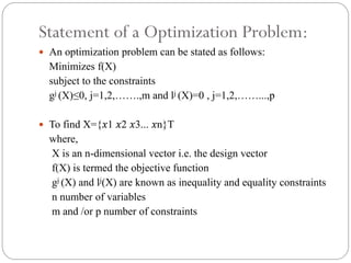
Download as PDF, PPTX


![ Problem Formulation:-
o Minimize,
Volume = f(R1;R2;R3;R4;W) [10 mm3]
o Subject to,
0 ≤VM ≤ 349:33 [1 MPa]
25≤ R1 ≤ 45 [1 mm]
15 ≤ R2 ≤ 45 [1 mm]
5 ≤ R3 ≤ 45 [1 mm]
5 ≤ R4 ≤ 45 [1 mm]
5 ≤W ≤ 170 [1 mm]](https://image.slidesharecdn.com/cadbasedshapeoptimization-131009041818-phpapp02/85/Cad-based-shape-optimization-13-320.jpg)


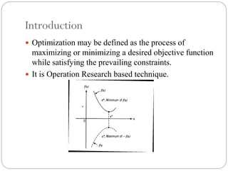
The document discusses the principles of optimization in engineering design, focusing on maximizing or minimizing objective functions while adhering to constraints. It explains different optimization techniques, including mathematical programming, stochastic processes, and statistical methods, and highlights software tools used in optimization such as ANSYS and CATIA. Additionally, it presents a practical example of optimization in a bracket design, which led to a significant reduction in weight and cost.