The document describes the 5-step process for formulating an optimization design problem:
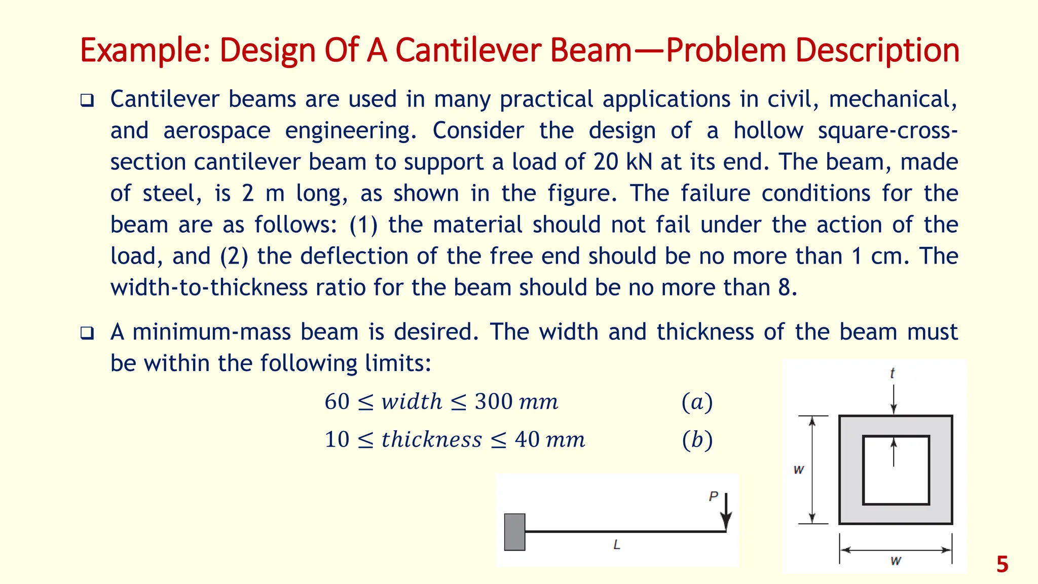
1) Describe the project and objectives
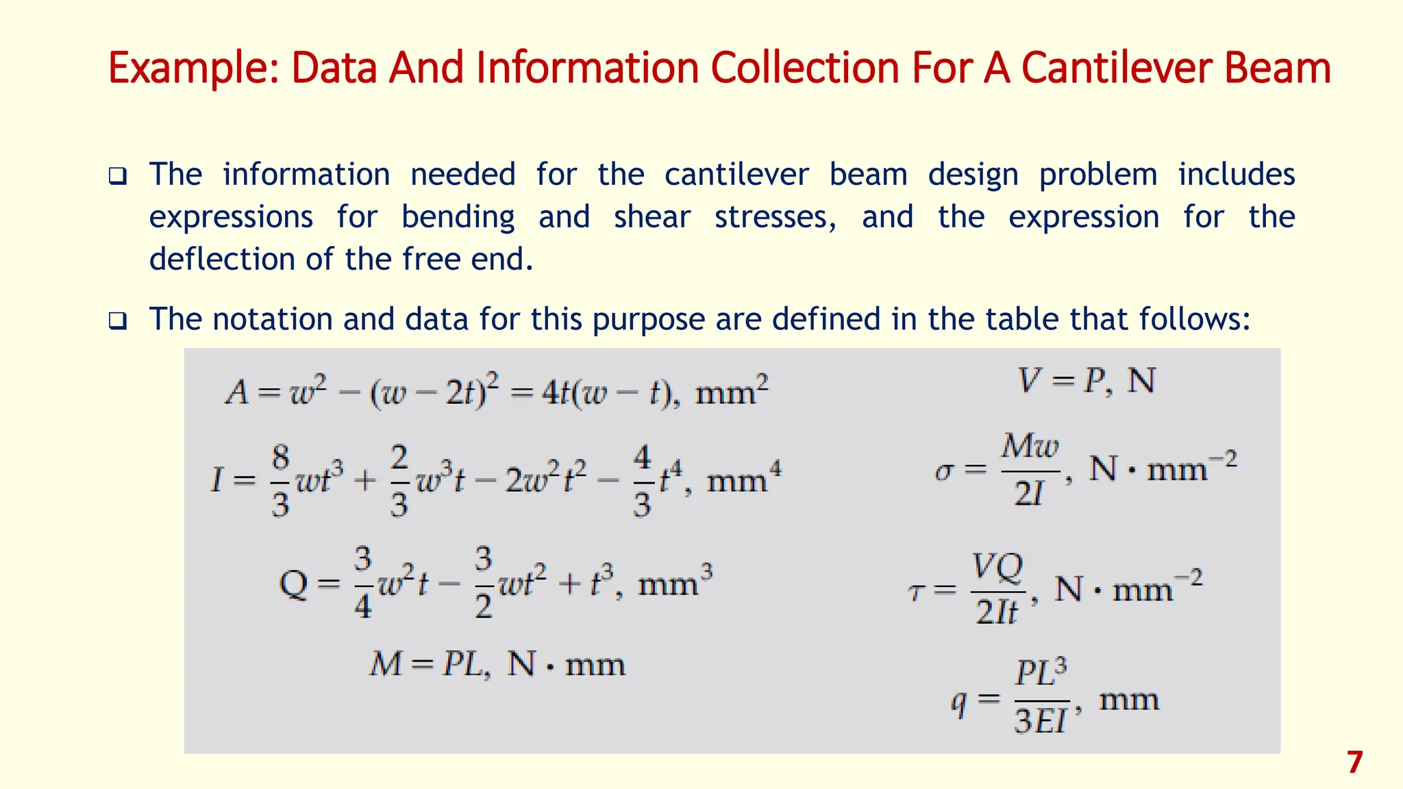
2) Collect relevant data and analysis tools
3) Define design variables that can be adjusted to produce different designs
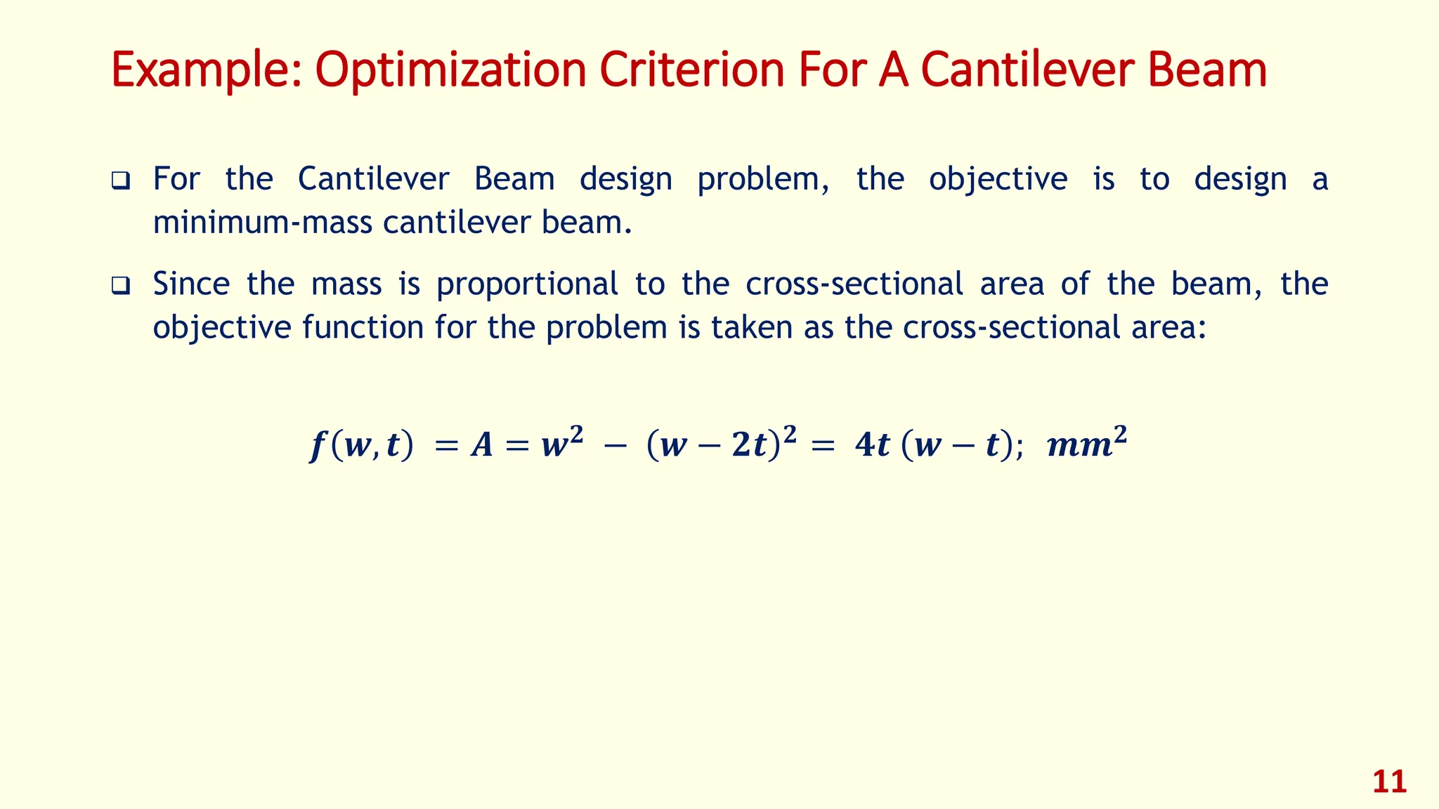
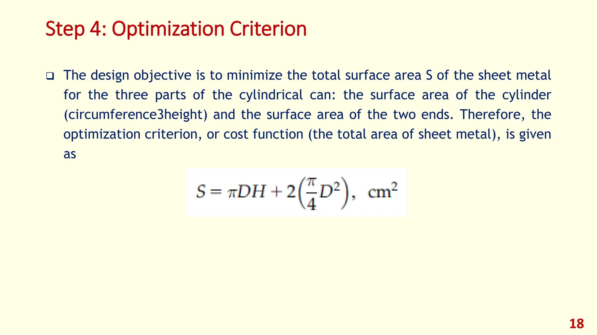
4) Select an optimization criterion to evaluate designs, such as minimizing cost
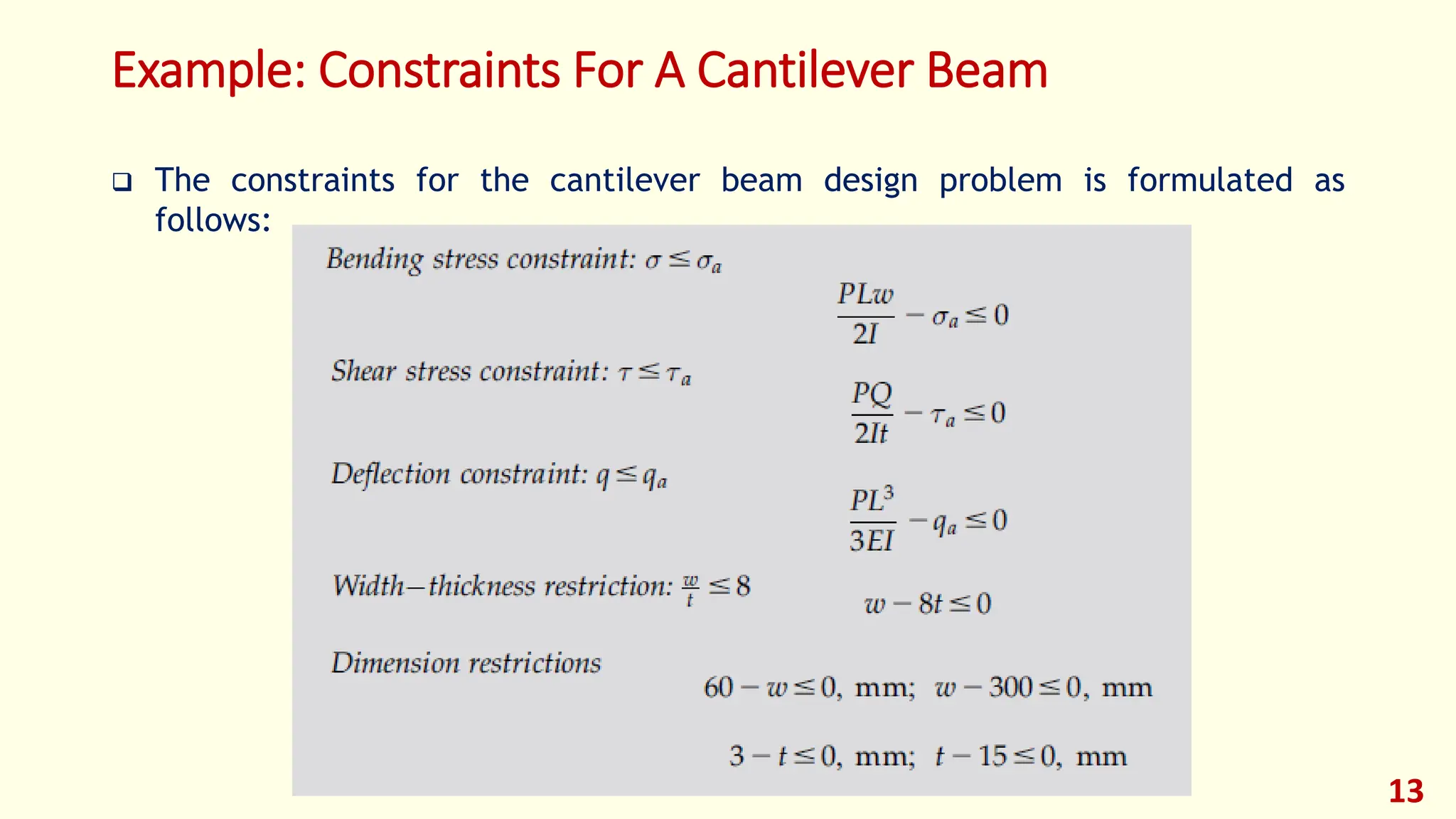
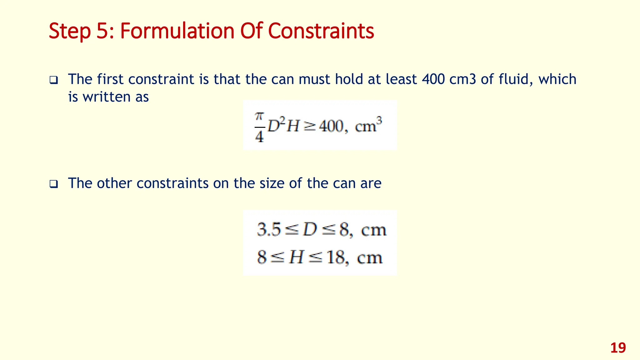
5) Identify constraints on the design such as performance requirements or limits on variables
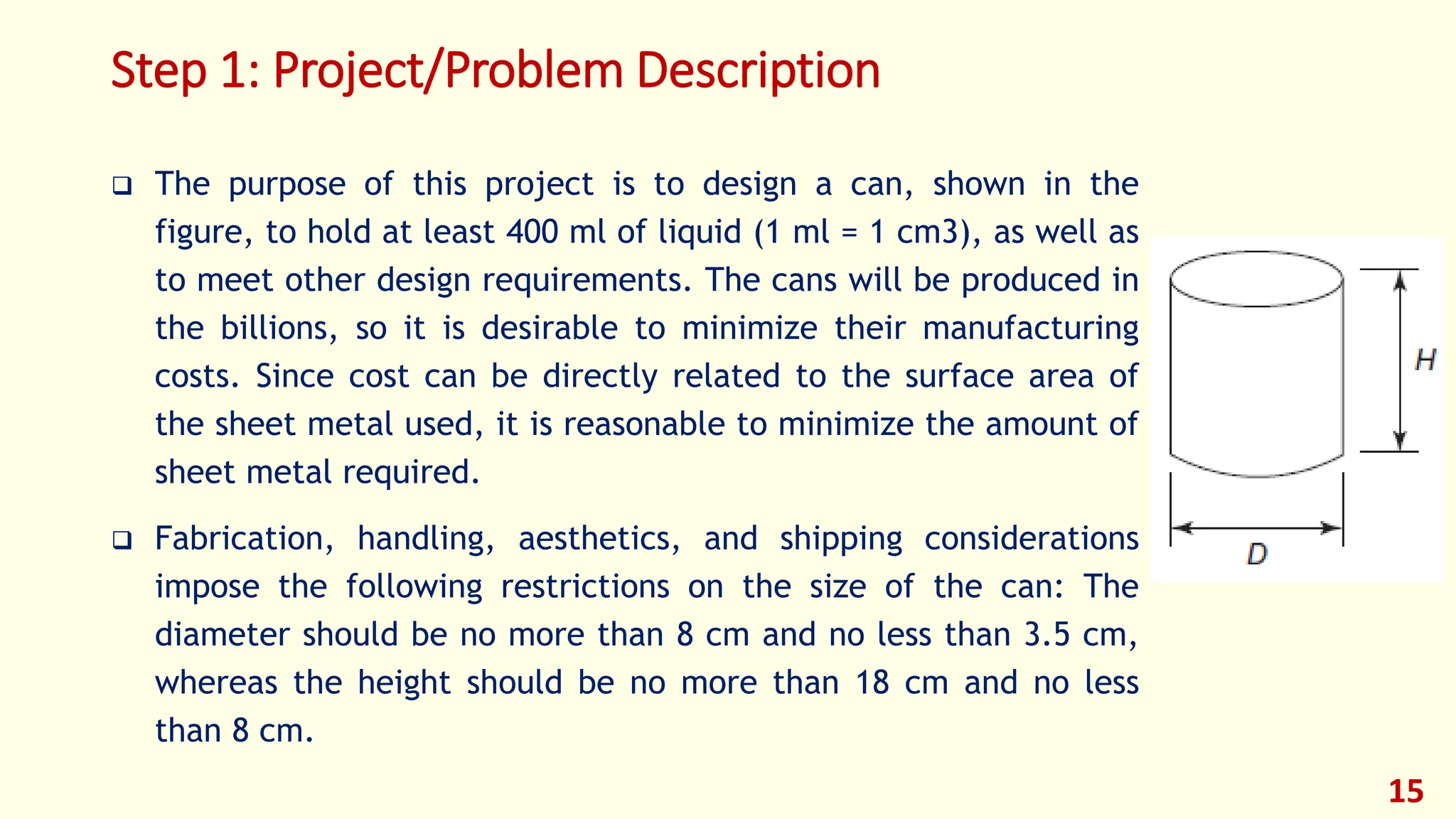
It provides an example of using this process to design a minimum surface area can, with diameter and height as design variables, total surface area as the criterion to minimize, and constraints on volume and size limits.