Download as PDF, PPTX
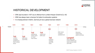
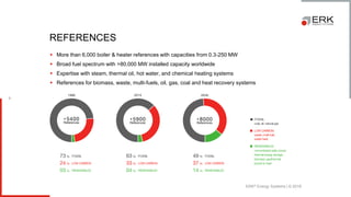
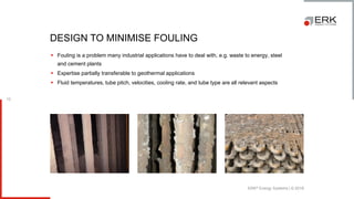
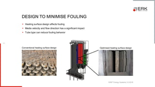
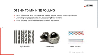
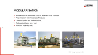
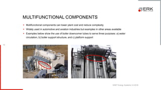
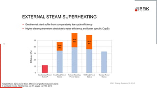
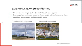
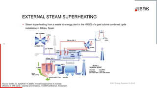
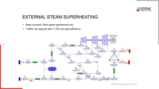

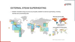
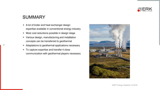

The document presents an overview of erk® energy systems, detailing its history, expertise in boiler and combustion systems, and significant installed capacity worldwide. It discusses design strategies to minimize fouling in heating systems, including the use of modularization and multifunctional components to enhance efficiency and reduce costs. Additionally, the document emphasizes the importance of adapting conventional energy design practices for geothermal applications and the role of external steam superheating in improving cycle efficiency.


