Download to read offline
![IOSR Journal of Mechanical and Civil Engineering (IOSR-JMCE)
e-ISSN: 2278-1684,p-ISSN: 2320-334X, Volume 13, Issue 1 Ver. II (Jan. - Feb. 2016), PP 13-20
www.iosrjournals.org
DOI: 10.9790/1684-13121320 www.iosrjournals.org 13 | Page
Concrete beams Flexural under sustained loading
Abdelmonem Masmoudi1
Mongi Benouezdou2
Jamel Bouaziz3
1
Université de Sfax, Department of civil engineering, ENIS, Sfax, Tunisia
2
Visiting Professor at the University of Sharjah, College of Engineering, , United Arab Emirates.
3
Department of industrial chemistry, ENIS , Sfax, Tunisia
Abstract: Steel reinforced concrete structures are susceptible to corrosion in severe environments. Corrosion
limits the service life of structures, and results in expensive maintenance costs. GFRP composite bars are
excellent alternative to steel bars for reinforcing concrete structures in severe environments. However, there is
limited experience with the design and construction of GFRP reinforced concrete structures. This report
investigates some parameters used in design of GFRP reinforced concrete members following the Eurocode 2
recommendations. A ratio of Agfrp bar reinforcement equal to 2% is recommended to a stabilization of the
constraint in the bar. The compressed part of the concrete must be limited and does not exceed 40% useful
height of the beam.
Keywords: GFRP Bar reinforcement, failure, Flexural design, Sustained loading
I. Introduction
When considering a design utilizing GFRP Rebar, the differences in physical properties and
performance characteristics must be taken into account. Of chief importance to the designer is the fact that all
FRP’s are linear elastic up to failure and exhibit no ductility or yielding. In traditional steel reinforced concrete
design, a maximum amount of steel reinforcing has been specified so that the steel is the weak link in a structure.
When weakened, the steel rebars stretch or yield and give a warning of pending failure of the concrete member.
When using GFRP Rebars, ACI committee 440’s design guidelines recommend a minimum amount of GFRP
rebar rather than a maximum. If a member fails, the concrete will be the weak link and will crush in compression.
The crushing concrete will serve as the warning of failure and there will still be ample reserve tensile capacity in
the GFRP reinforcing. Another major difference is that serviceability will be more of a design limitation in GFRP
reinforced members than in steel reinforced members. Due to its lower modulus of elasticity, deflection and crack
width will affect the design. Deflection and crack width serviceability requirements will provide additional
warning of failure prior to compression failure of the concrete. In many instances, deflection and crack width will
control design. Detailed design guidance can be found in the American Concrete Institute publication "Guide for
the Design and Construction of Concrete Reinforced with FRP Bars". Design Guidelines for GFRP Reinforced
Concrete have been published 1,2,3,4].
K Coefficient in consideration of non –linear stress distribution
fct.eff Effective tensile just before cracking
fe Allowable stress immediately after cracking
σgfrp Characteristic constraint
ULS Ultimate Limit State
SLS Serviceability Limit State
g Regulatory safety coefficient
g GFRP bar deformation
gl Limit GFRP bar deformation
b Width of concrete beam
d Effective depth of cross section
h Depth of the concrete beam
E Modulus of elasticity of GFRP bar
Mrc Resistant Moment concrete
Muls Moment with the Ultimate Limit State
µ Reduced moment
Nc Compressive force in the concrete
Ngfrp GFRP bar traction effort
fc Stresses in the concrete
yul Position of the neutral axis](https://image.slidesharecdn.com/c013121320-160727050416/85/C013121320-1-320.jpg)
![Concrete beams Flexural under sustained loading
DOI: 10.9790/1684-13121320 www.iosrjournals.org 14 | Page
Since the structural failure due to FRP reinforcing bar rupture is rather catastrophic, the over-reinforced
design concept that ensures that compressive failure of concrete takes place prior to the tensile failure of FRP has
been accepted 5,6,7].Nanni pointed out that, for FRP reinforced concrete beams, the balanced reinforced ratio,
which is defined as the reinforcement ratio producing a condition for simultaneous failure of the concrete and the
FRP reinforcing bar, is much lower than the practically adopted reinforcement ratio if the concrete is confined
8]. The modulus of elasticity of most available FRP materials is only 1/5 to 1/3 that of steel, which results in
larger deflections as well as larger crack widths under service loads in comparison with those of its counterpart
steel-reinforced concrete element for a given reinforcement ratio 9,10,11,12].
Strength and stiffness of a composite material are defined by the type, amount and orientation of the
strengthening fibers. The fibers of Schock Combar are oriented linearly, resulting in the highest possible axial
tensile strength, thus these GFRP bars remains linearly elastic up to failure. When the tensile strength of the
material is exceeded, yielding does not occur. However, GFRP shows relatively low tensile and compressive
strength perpendicular to the fibers 13].
Much research showed that same the decreases of 30% of the GFRP bars bond strength compared to
steel does not affect the correct operation of the reinforced concrete 14,15]. Active efforts are also underway for
a European Euro code 2 16], under the efforts of FIB Task Group 9.3 "FRP (Fibre Reinforced Polymer)
Reinforcement for Concrete Structures. The use of competent experienced engineering personnel should always
be employed in the design and construction of concrete reinforced structures.
II. Experimental Study
2.1 Beam description
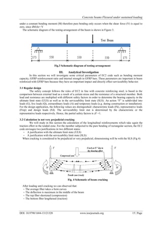
A total of six RC beam specimens of dimensions, 150 mm x 200 mm x 2000 mm, were fabricated with
concrete cover of 20 mm. For the tensile reinforcement, two 12 mm diameter were used, and for the
compressive reinforcement, two 8 mm diameter. Properties of the GFRP and steel bars used in this study and the
details of beam cross-section are shown in table 117], and Figure 1.
Fig. 1 GFRP bars reinforcement and Beam
2.2 Test set-up and instrumentation
The beams were subjected to sustained loads for a period of 30 days to compare under sustained
loading the deflection of the beams reinforced with GFRP and steel bars in ambient laboratory condition. To
simulate the sustained loading, beams were placed at one-four points us shown in Fig 2.
Fig. 2 Beam test instrumentation
The mid-span deflection was monitored by a Linear Variable Displacement Transducer (LVDT) with
accuracy equal to 0.001mm, placed underneath the center of the beam. All the beams were tested simply
supported at the age of 28 days under four-point loading.
Pure bending is a condition of stress where a bending moment is applied to a beam without the
simultaneous application of axial, shear, or torsional forces. Pure bending is the flexure (bending) of a beam
Ø 8
2Ø 12 : Longitudinal reinforcement
: Transversal reinforcement
2000](https://image.slidesharecdn.com/c013121320-160727050416/85/C013121320-2-320.jpg)
![Concrete beams Flexural under sustained loading
DOI: 10.9790/1684-13121320 www.iosrjournals.org 19 | Page
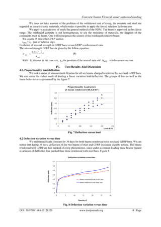
4.3 Live load according to Mrc and the deflection
In comparison with the steel bars, the GFRP bars have a weaker modulus of elasticity, which leads to a
larger deflection, with equal load and span. Consequently, in much of case, the serviceability limit state (the
deflection) could control the dimensioning of a beam in bending. The live load was calculated in two manners.
The first process was to calculate Q according to Resistant Moment concrete Mrc calculation and the second
according to the deflection.
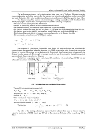
Fig. 9 : Evolution of the constraint versus GFP ratio
We can notice according to figure 9, that in two situations the deflection does not control dimensioning
in bending. In the range of value of Agfrp recommended (between Agfrp and 1.2* Agfrp ). This value recommended
(economic) corresponds to a stabilization of the constraint in the bar (0.02).
V. Conclusions
From the analytical and experimental investigation carried out, the following conclusions can be
drawn:
- For values weak of loading, there is a linear variation load/deflection.
- Deflection of the two beams of steel and GFRP increases slightly in time.
- Beams reinforced with GFRP are less marked of creep phenomenon.
- The effect of sustained loading is more detrimental in beams reinforced with steel bars than in those with
GFRP bars
- Deflection does not control dimensioning in bending. In the range of value of Agfrp recommended (between
Agfrp and 1.2* Agfrp ). This recommended value (economic) corresponds to a stabilization of the constraint in
the bar (Ratio = 0.02).
- The compressed part of the concrete in such way that the neutral axis yul must be limited and does not
exceed 40% useful height of the beam
Acknowledgements
The authors would like to thank the manufacturer of the GFRP Combar (Schöck, Baden-Baden,
Germany) for providing the GFRP bars. The opinion and analysis presented in this paper are those of the
authors.
References
[1] Design Guidelines for GFRP Reinforced Concrete (1997) published by the ASCE Journal of Composites for Construction (Aug
1997 Vol.1 No 3 ISSN 1090-0268 Coden: JCCOF2).
[2] ACI Committee 4401R-06, "Guide for the Design and Construction of Concrete Reinforced with FRP Bars, American Concrete
Institute, Farmington Hills. Branson, , McGraw-Hill, New York, 1977, 546pp
[3] ACI Committee 435, “State-of-the-Art Report, Deflection of Two Way Reinforced
[4] Concrete Floor Systems,” ACI SP 43-3, Deflections of Concrete Structures, 1974, pp. 55- 8182/23. Berkeley: EERC. University of
California, CA., USA
[5] Sonobe, Y et al, Design Guidelines for GFRP Reinforced Concrete building Structures (1997) Journal of Composite for
construction , V 1 No 3 Aug pp. 90-113
[6] Theriault et al. (1198), Effect of FRP reinforcement ratio and concrete strength on flexural behaviour on flexural of concrete beams.
Journal of Composite for construction , V 2 No 1 Feb. pp. 7-15
[7] Nanni.A (1993) Flexural behaviour and design of RC members using FRP reinforcement Journal of structural engineering V.119
No 11 Nov 1993 pp. 3344-339
[8] Nawy, E et al.(1971). Fiberglass reinforced concrete slabs and beams ASCE journal of the structural division V.97. N° ST9 pp.
2203-2215
[9] Nawy, E et al.(1997). Fiber glass reinforced concrete slabs and beams ASCE journal of the structural division V.103. N° ST2 pp.
421-428
0
100
200
300
400
500
600
700
0 0,01 0,02 0,03 0,04 0,05 0,06
GFRPbarstrength(MPa).
Ratio (GFRP)](https://image.slidesharecdn.com/c013121320-160727050416/85/C013121320-7-320.jpg)
![Concrete beams Flexural under sustained loading
DOI: 10.9790/1684-13121320 www.iosrjournals.org 20 | Page
[10] Faza, S et al (1993) Theoretical and experimental correlation of behavior of concrete beams reinforced with fiber reinforced plastic
rebars. Proceeding of international symposium SP 138. A Nanni and C.W. Dolan. eds. American concrete institute Famington
Hills, Mich, 1993, pp. 599-614
[11] Benmokrane et al. (1996) Flexural response of concrete beams reinforced with FRP Reinforceing bars ACI Structural Journal V.93
N°.1 1996, pp46-55
[12] Aboutaha R (2004) Recommended Design for the GFRP Rebar Combar, Syracuse University, Department of Civil and
Environmental Engineering, Technical report, sponsored by Schok Bauteile GmbH ,U SA
[13] Masmoudi A., (2010), Effet de la température et de l’eau sur les propriétés d’adhérence des barres polymères renforcées de fibre de
verre avec le béton, Thèse de Doctorat ENIT Université Tunis el Manar, 176p
[14] ACI Committee 435, “Allowable Deflections”, ACI Journal, Proceedings V. 65, No. 6, 1968, pp. 433-444.
[15] Bank L. et al. (2003). A Model Specification for Composites for Civil Engineering Structures. Construction and Building
Materials,vol. 17(6-7), pp.405-437.
[16] EC2, Norme Européenne, Eurocode 2, (2008), Calcul des structures en béton, Partie1: règles générales et règles pour les bâtiments
[17] Schock Bauteil GmbH Combar (2006) Design Guideline for Concrete Structures Reinforced with Glass Fiber Reinforced Polymer
following the Requirements of DIN 1045-1and EC2 Issued Germany.26p](https://image.slidesharecdn.com/c013121320-160727050416/85/C013121320-8-320.jpg)

This document discusses experimental and analytical investigation of concrete beams reinforced with glass fiber reinforced polymer (GFRP) bars under sustained flexural loading. Key points: - Six concrete beam specimens reinforced with GFRP bars were tested under sustained loading for 30 days to compare deflection to beams reinforced with steel bars. - Analytical calculations were performed to investigate parameters in Eurocode 2 for designing GFRP reinforced concrete beams, including bending moment capacity, GFRP reinforcement ratio, and stress limits in the GFRP bars. - A minimum GFRP reinforcement ratio of 2% is recommended to stabilize stresses in the bars. The compressed concrete zone should be limited to less than 40% of the beam depth