Retrofitting of Beam-Column Joint using Carbon Fibre Reinforced Polymer and Glass Fibre Reinforced Polymer
The document discusses the need for retrofitting of reinforced concrete structures to restore strength and functionality that may have deteriorated due to various factors, including changing loading conditions and environmental impacts. It outlines various retrofitting techniques and materials, particularly focusing on the use of carbon and glass fiber reinforced polymers (CFRP and GFRP) for strengthening beam-column joints. The results demonstrate significant increases in joint strength after retrofitting, showcasing its effectiveness in enhancing structural integrity.
Introduction to retrofitting, techniques, objectives, project planning, and types of repair materials.
Importance of retrofitting for structural integrity and techniques like shear walls, infills, and bracing.
Goals of enhancing strength, ductility, shear strength, and life span of structures with CFRP and GFRP.
Importance of choosing the right repair materials for effectiveness and properties to consider.
Analysis of various fibres used in retrofitting including density, strength, and compatibility.
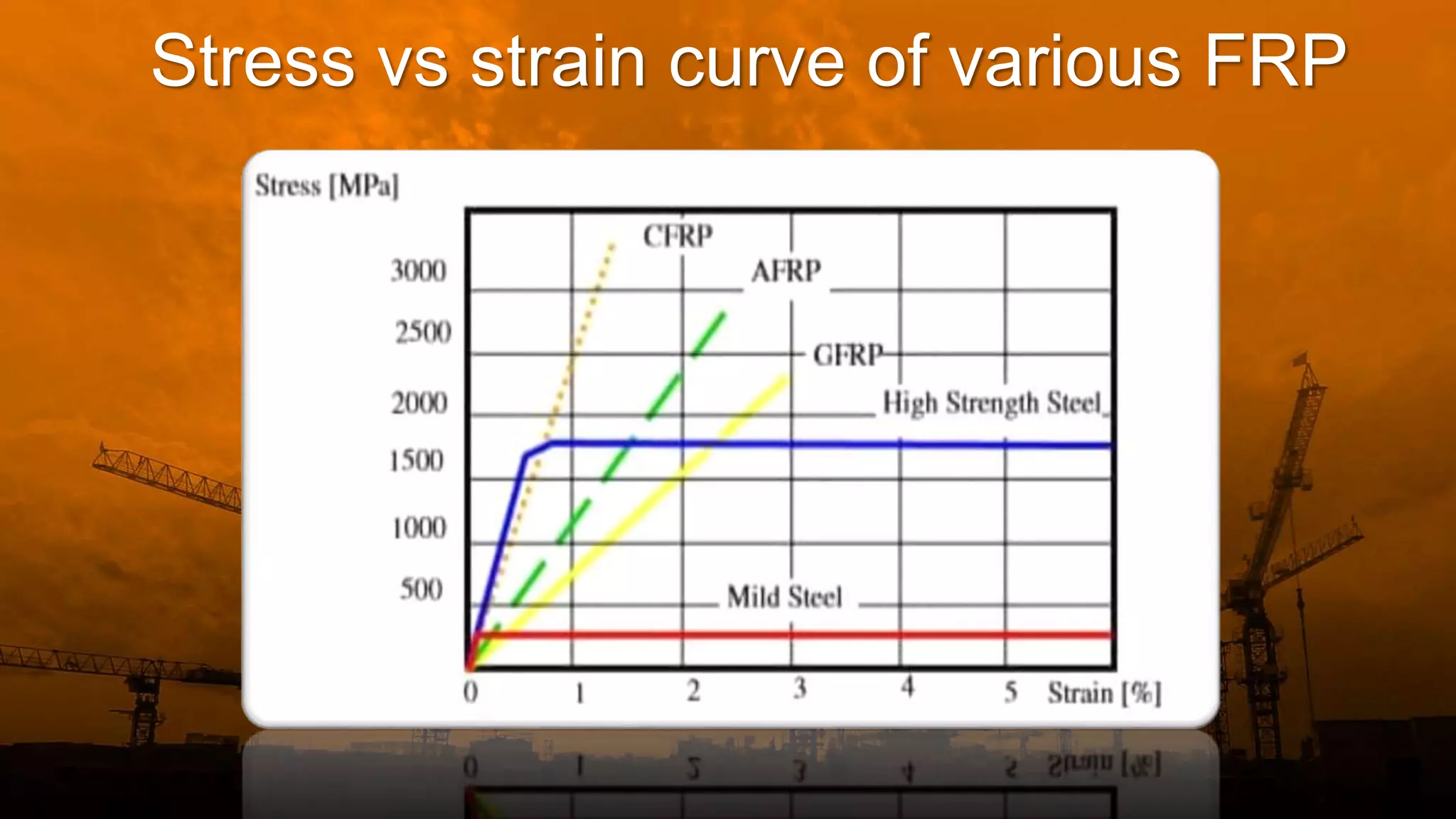
Stress vs. strain behavior of FRP, overview of GFRP and CFRP properties, and cost rates.
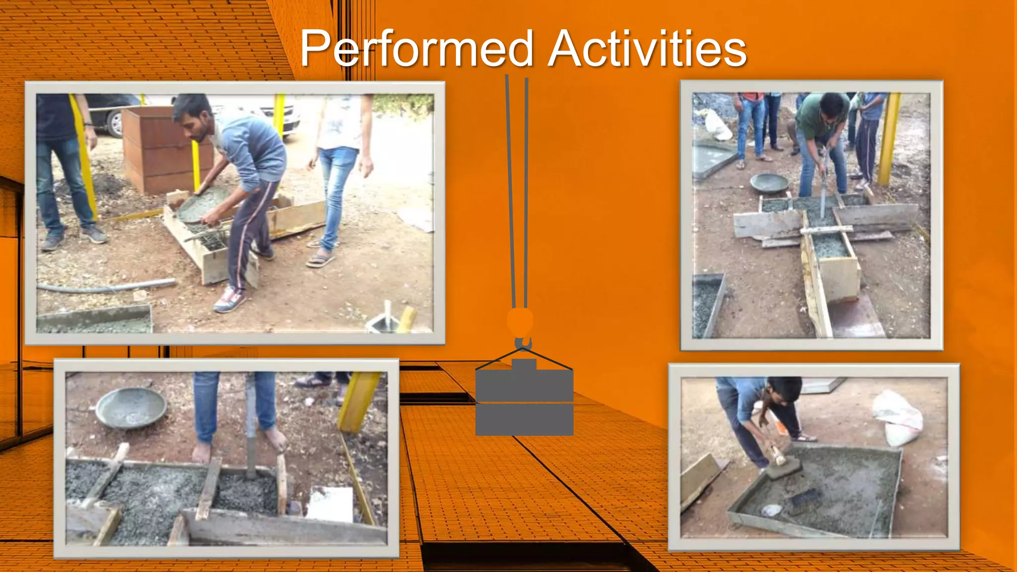
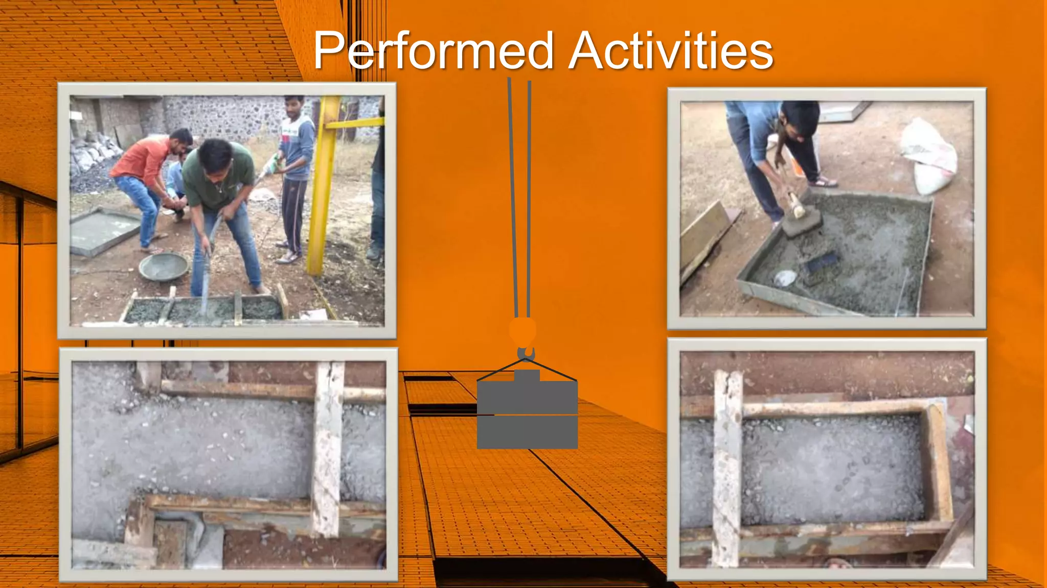
In-depth project planning, performed activities, frame assembly, and preparation for application of sheets.
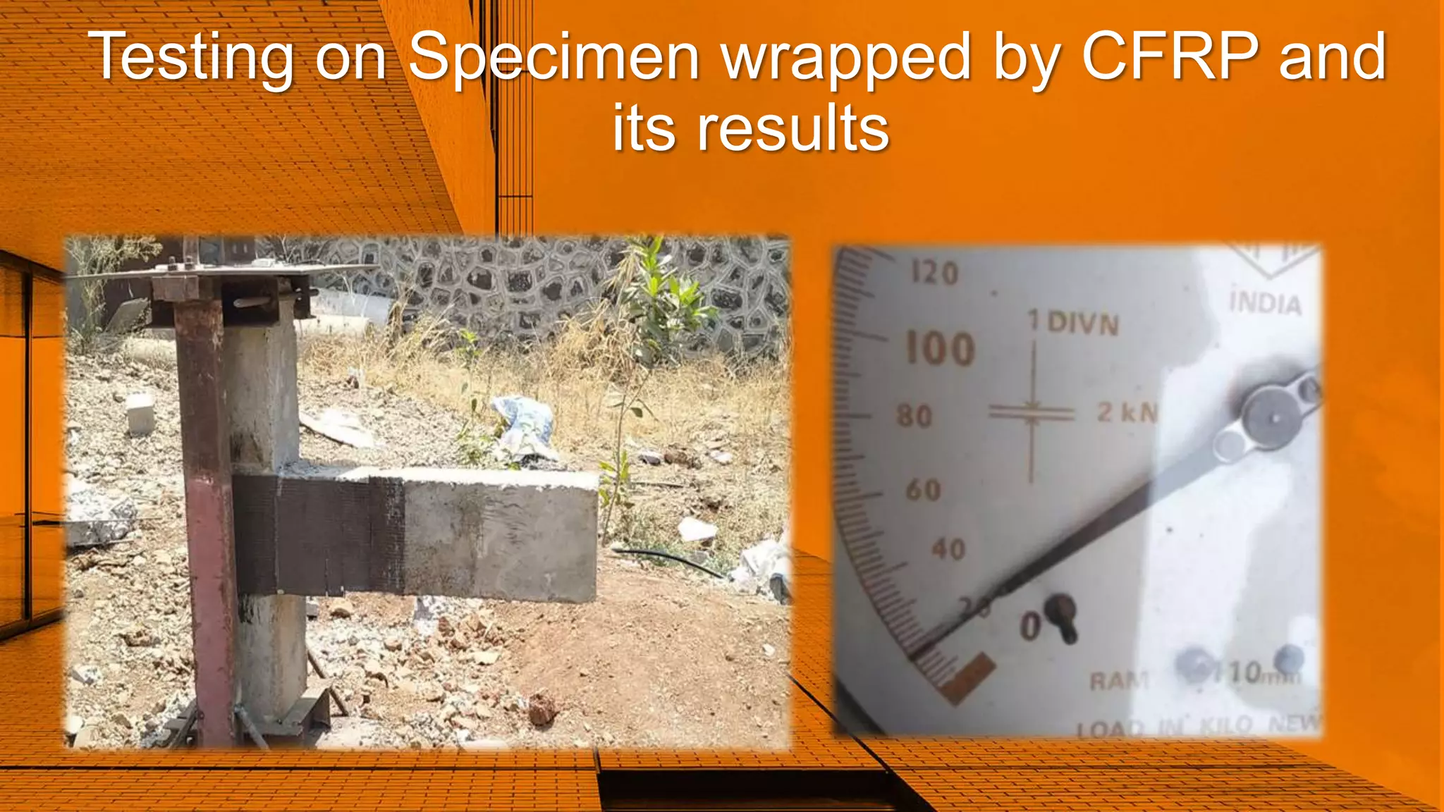
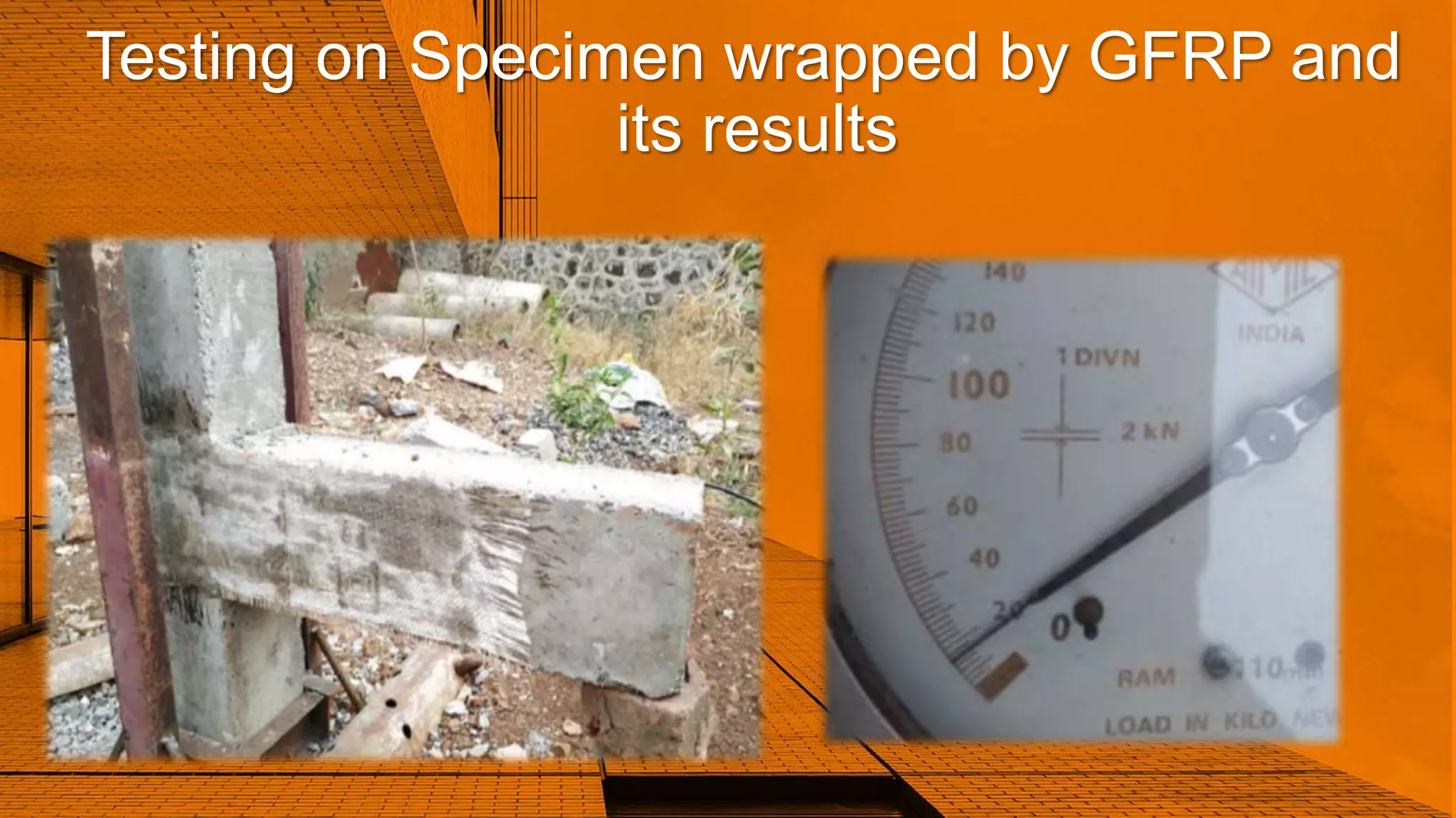
Results of tests on specimens wrapped with CFRP and GFRP showing strength improvements and crack patterns.Summary of findings on specimen strength increases with suggestions for future research.
Details on material quantities used in construction and compressive strength test results.
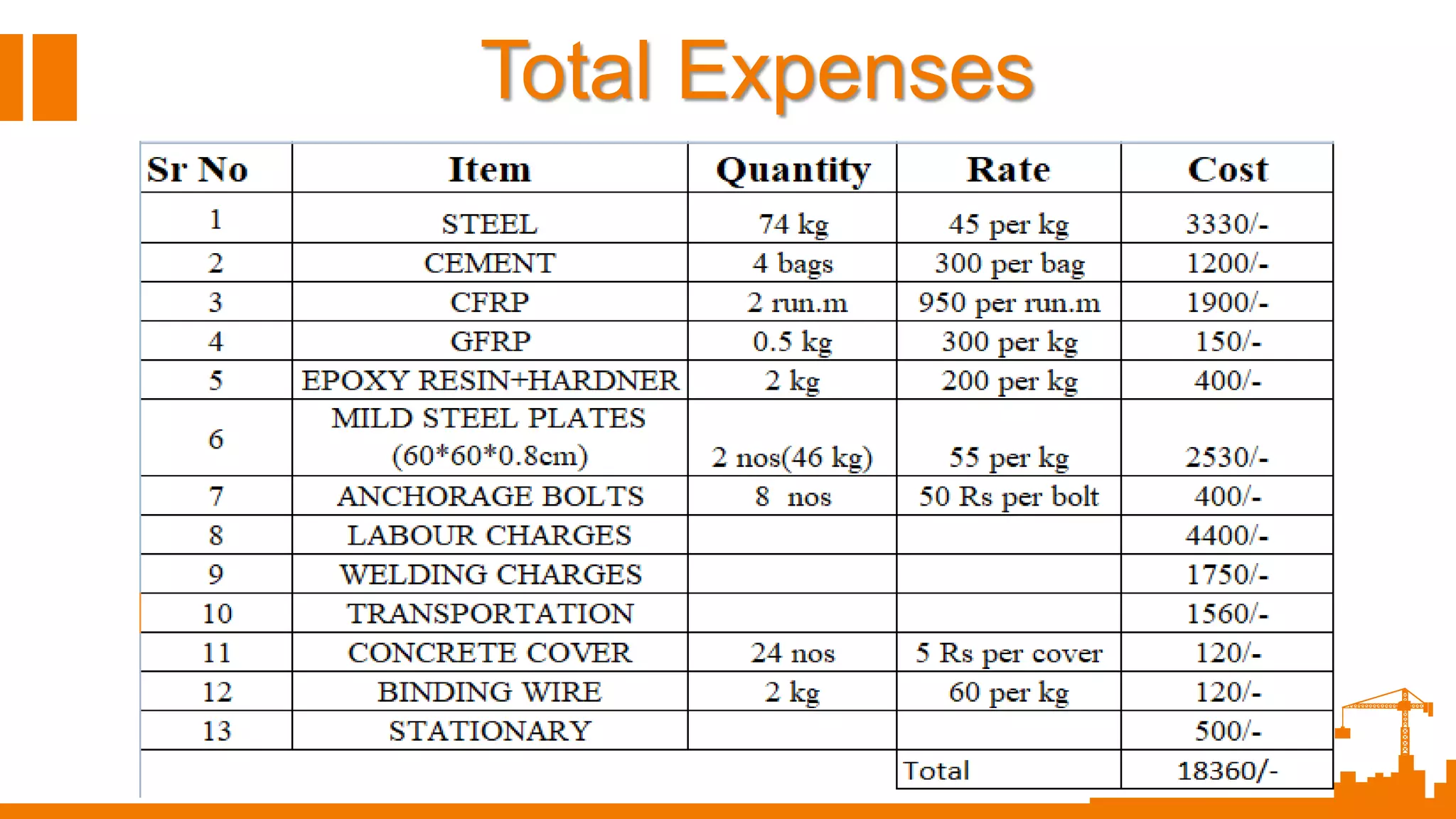
Summary of total expenses related to the retrofitting project.
Retrofitting of Beam-Column Joint using Carbon Fibre Reinforced Polymer and Glass Fibre Reinforced Polymer
2.
Overview
Introduction
a. Need ofRetrofitting
b. Retrofitting Techniques
01
Objective of project
Significance of project
Selection of Repair materia0
Essential parameters for repair material
Properties of fibres
Components of fibres
Stress vs. strain curve of FRP
CFRP and GFRP overview
Rates of CFRP and GFRP
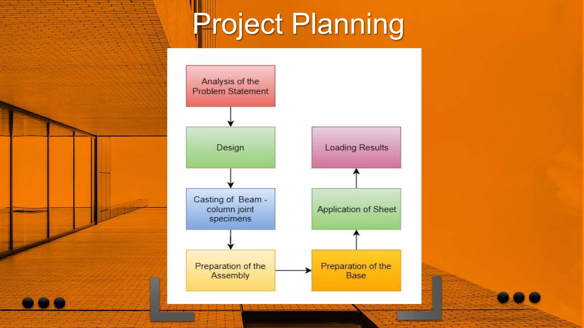
Project Planning
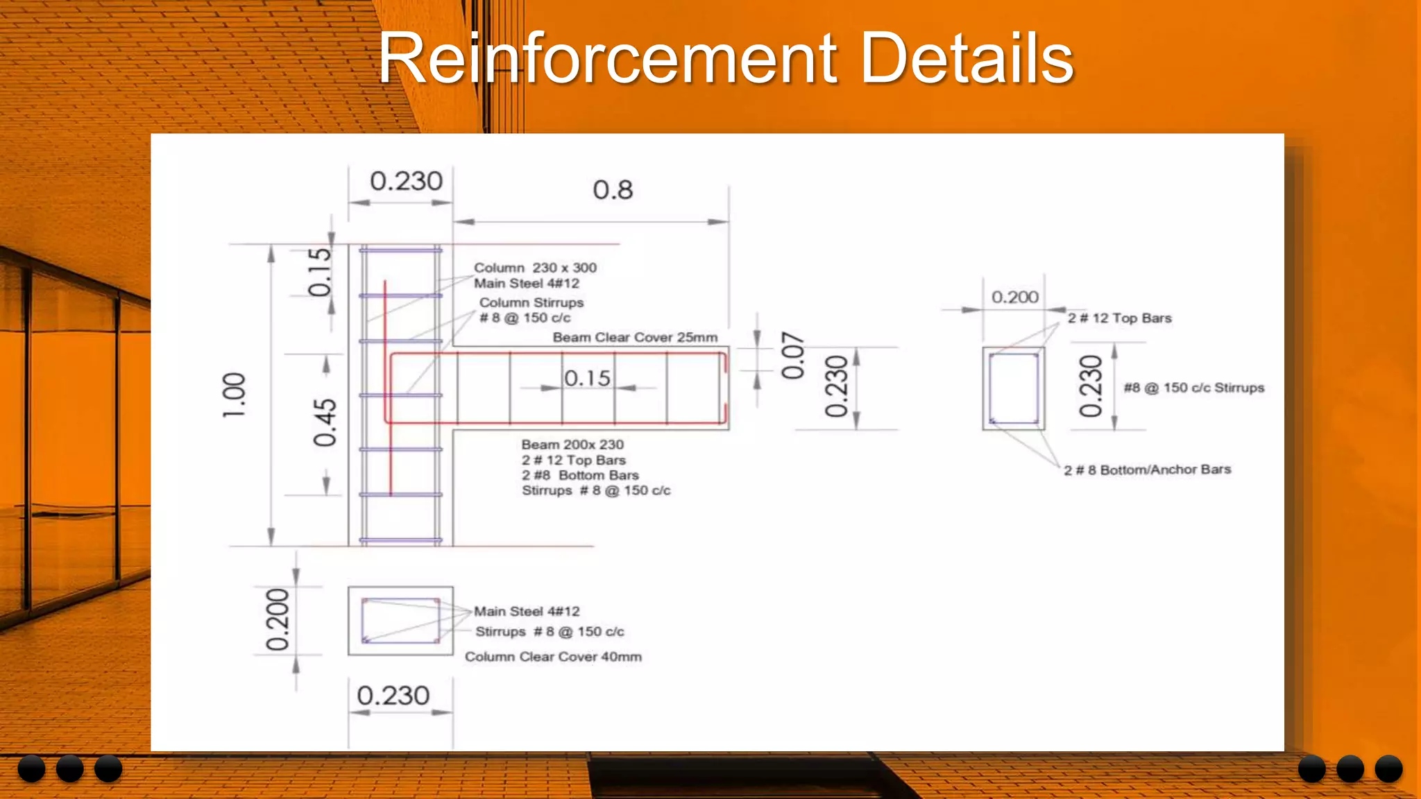
Reinforcement Details
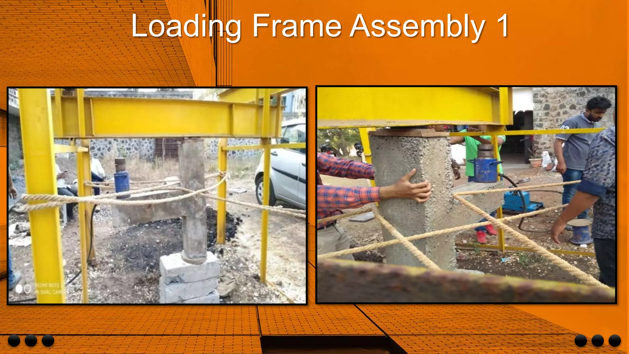
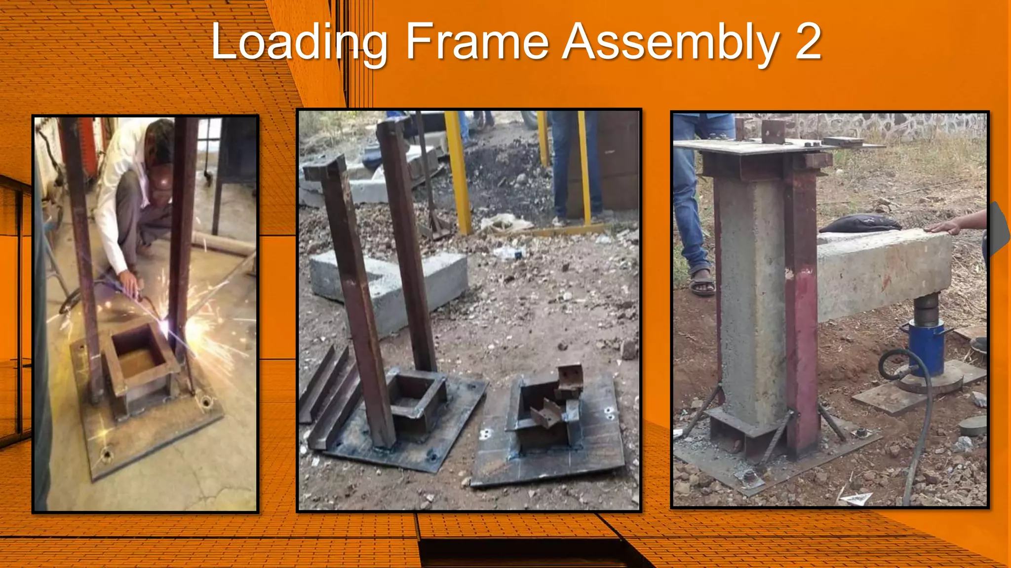
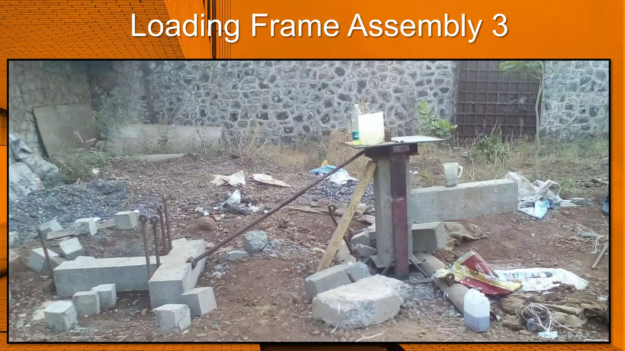
Loading Frame Assembly 1,2 and 3
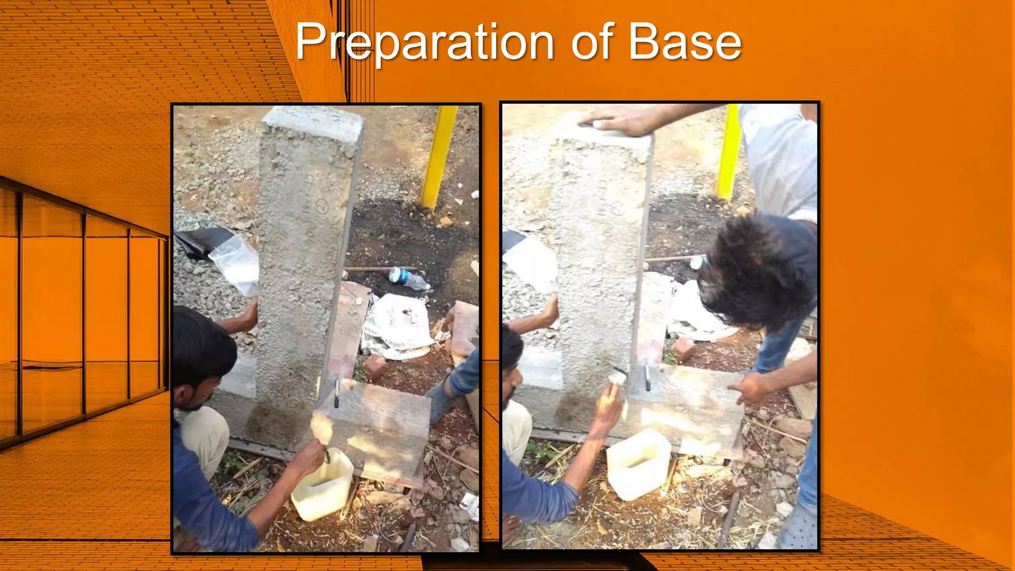
Preparation of Base
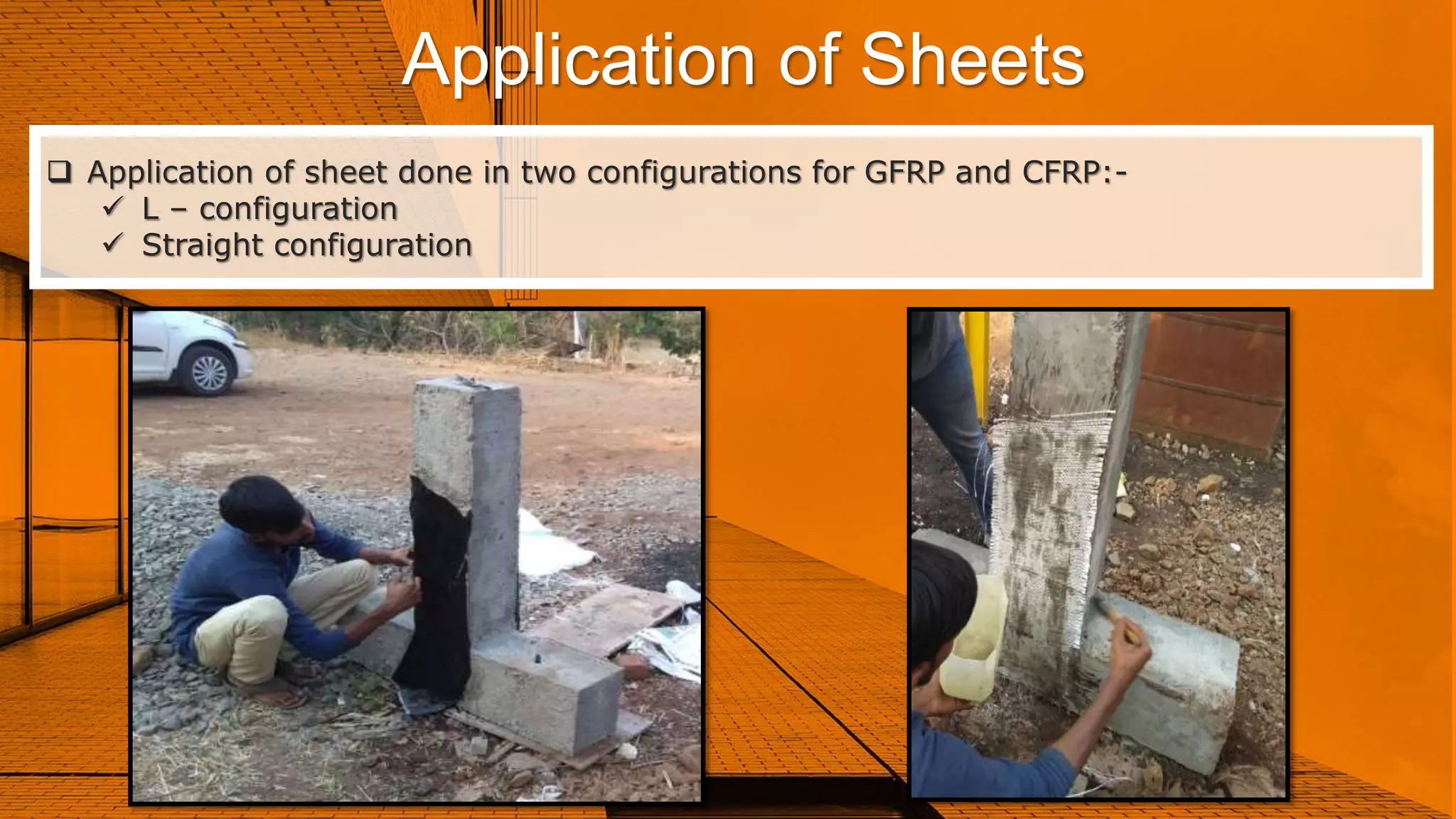
Application of Sheets
Mix Design
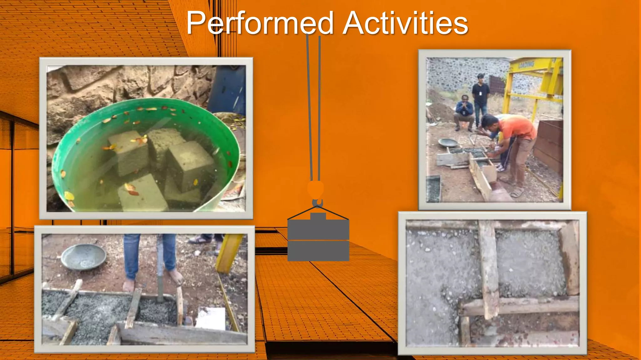
Performed Activities
02
03
04
05
06
07
08
09
10
11
12
13
14
15
16
17
3.
Introduction
Reinforced concrete isthe most commonly used material for the
construction of the structures which are designed in accordance of
the specifications given in the standard codes to meet the service
life.
During the service life if the loading conditions changes due to the
purpose of the structure like beam’s, column and slab this can result
in the non performance of the structure for which it is designed.
The structure are also susceptible to the deterioration due to the
earthquake, flood, cyclone, chloride attack, environmental pollution,
deficiencies of the material used, inadequate design and faulty
construction.
Replacement of the damaged structural element of the existing
particular structure has created the risk of the integrity of the
connecting members.
To restore the required strength of the deteriorated structure,
retrofitting is the only solution.
4.
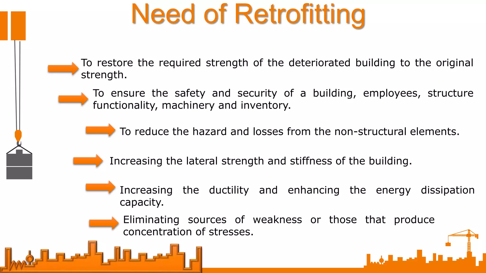
Need of Retrofitting
Torestore the required strength of the deteriorated building to the original
strength.
To ensure the safety and security of a building, employees, structure
functionality, machinery and inventory.
To reduce the hazard and losses from the non-structural elements.
Increasing the lateral strength and stiffness of the building.
Increasing the ductility and enhancing the energy dissipation
capacity.
Eliminating sources of weakness or those that produce
concentration of stresses.
5.
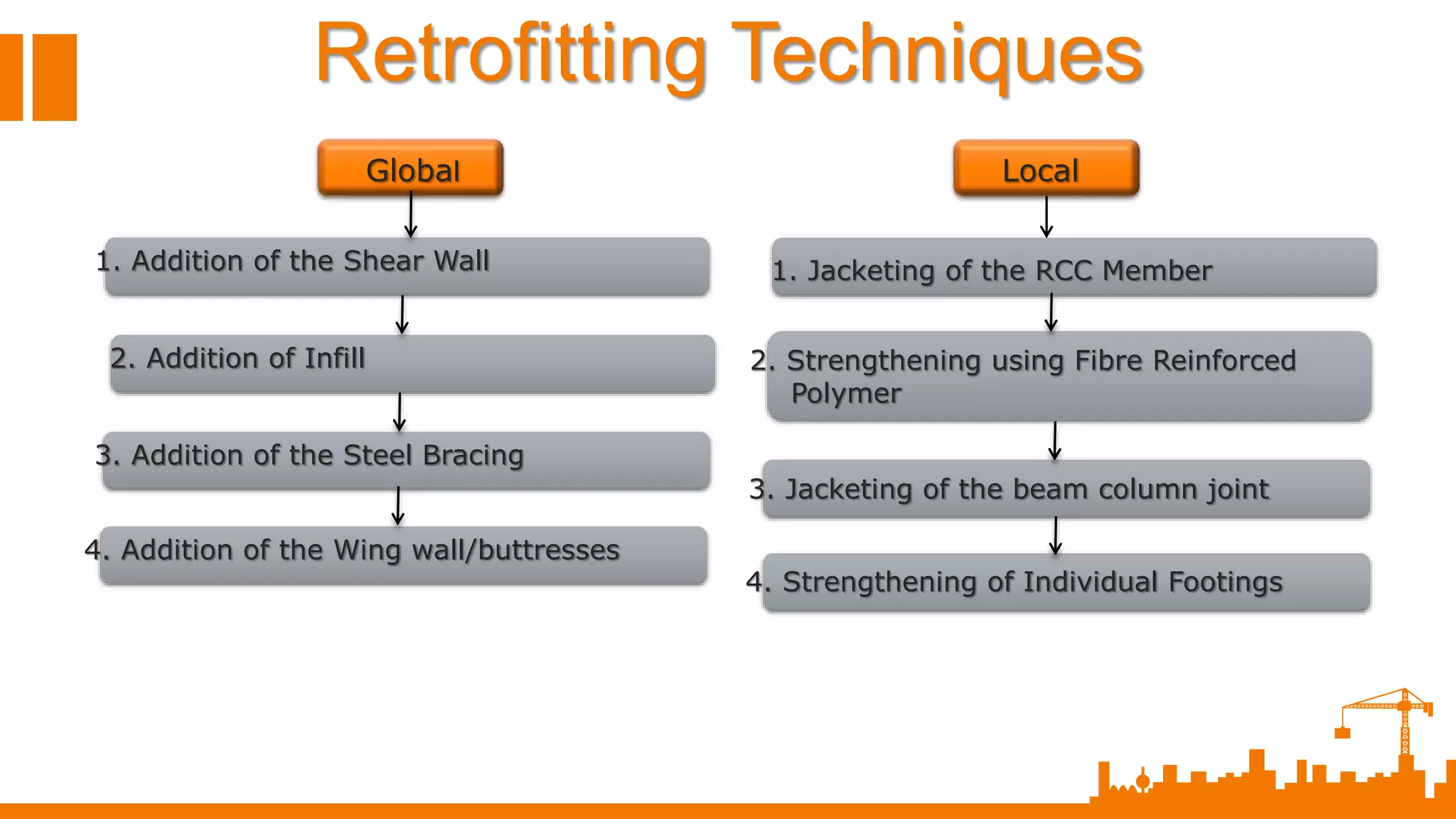
Retrofitting Techniques
Global
1. Additionof the Shear Wall
2. Addition of Infill
3. Addition of the Steel Bracing
4. Addition of the Wing wall/buttresses
1. Jacketing of the RCC Member
2. Strengthening using Fibre Reinforced
Polymer
3. Jacketing of the beam column joint
4. Strengthening of Individual Footings
Local
6.
Strengthening Works
Performance ofSpecimen
Load Carrying Capacity
Cost Efficiency
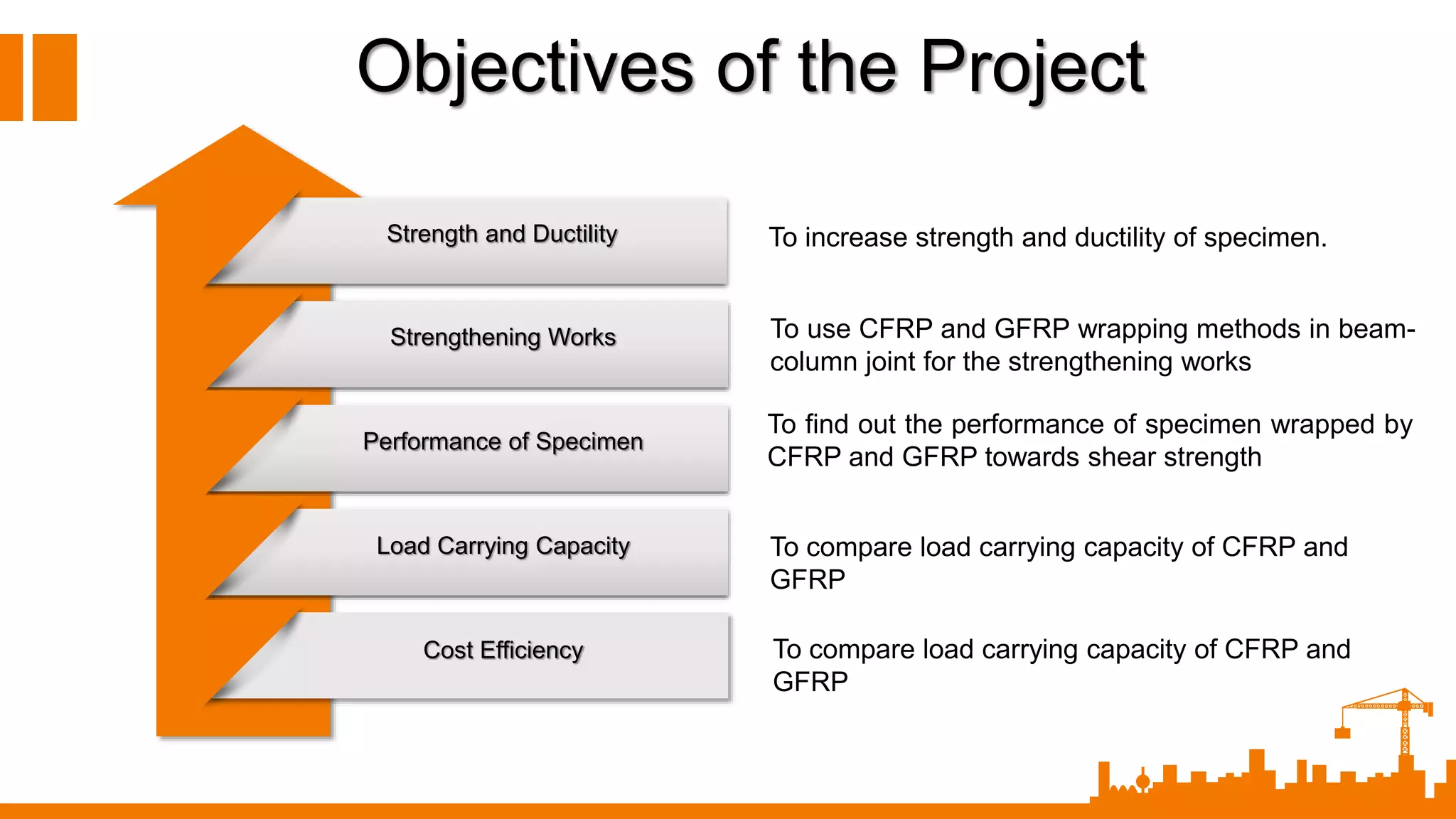
Objectives of the Project
Strength and Ductility To increase strength and ductility of specimen.
To use CFRP and GFRP wrapping methods in beam-
column joint for the strengthening works
To find out the performance of specimen wrapped by
CFRP and GFRP towards shear strength
To compare load carrying capacity of CFRP and
GFRP
To compare load carrying capacity of CFRP and
GFRP
7.
Shear Strength
Life Spanof Structure
Integrity of Joint
Cost Efficiency
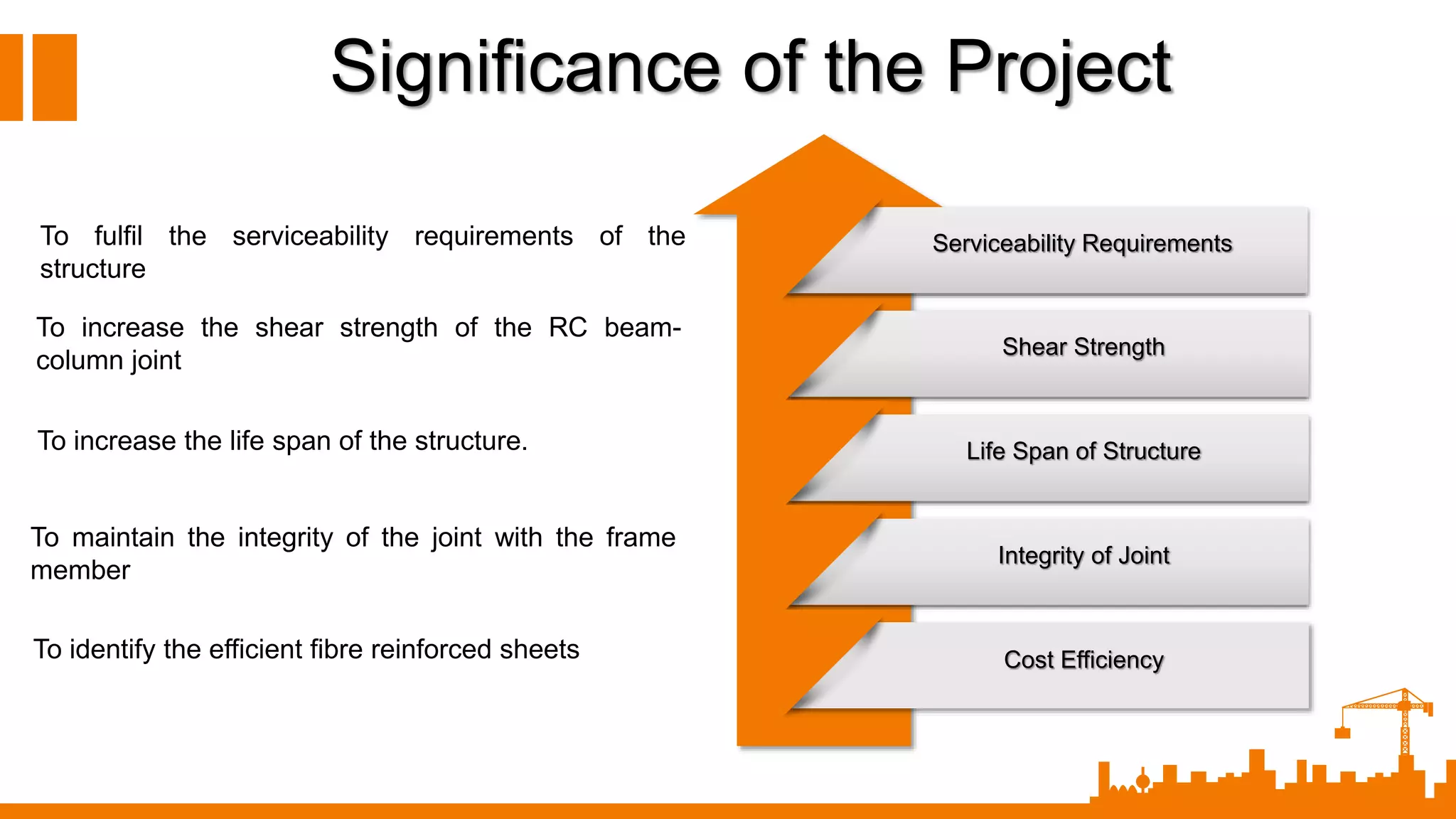
Significance of the Project
Serviceability RequirementsTo fulfil the serviceability requirements of the
structure
To increase the shear strength of the RC beam-
column joint
To increase the life span of the structure.
To maintain the integrity of the joint with the frame
member
To identify the efficient fibre reinforced sheets
8.
Selection ofthe repair material is one of the most important tasks for ensuring
durable and trustworthy repair.
Though pre-requisite for a sound repair system if detailed investigation and then
determine
the exact cause of the distress, yet an understanding of the process of the
deterioration of the repair materials
Under the service condition if vital of course availability of the materials of the
relevance, equipment and skilled labor have to be explored before deciding upon
repair.
Selection of the repair material
9.
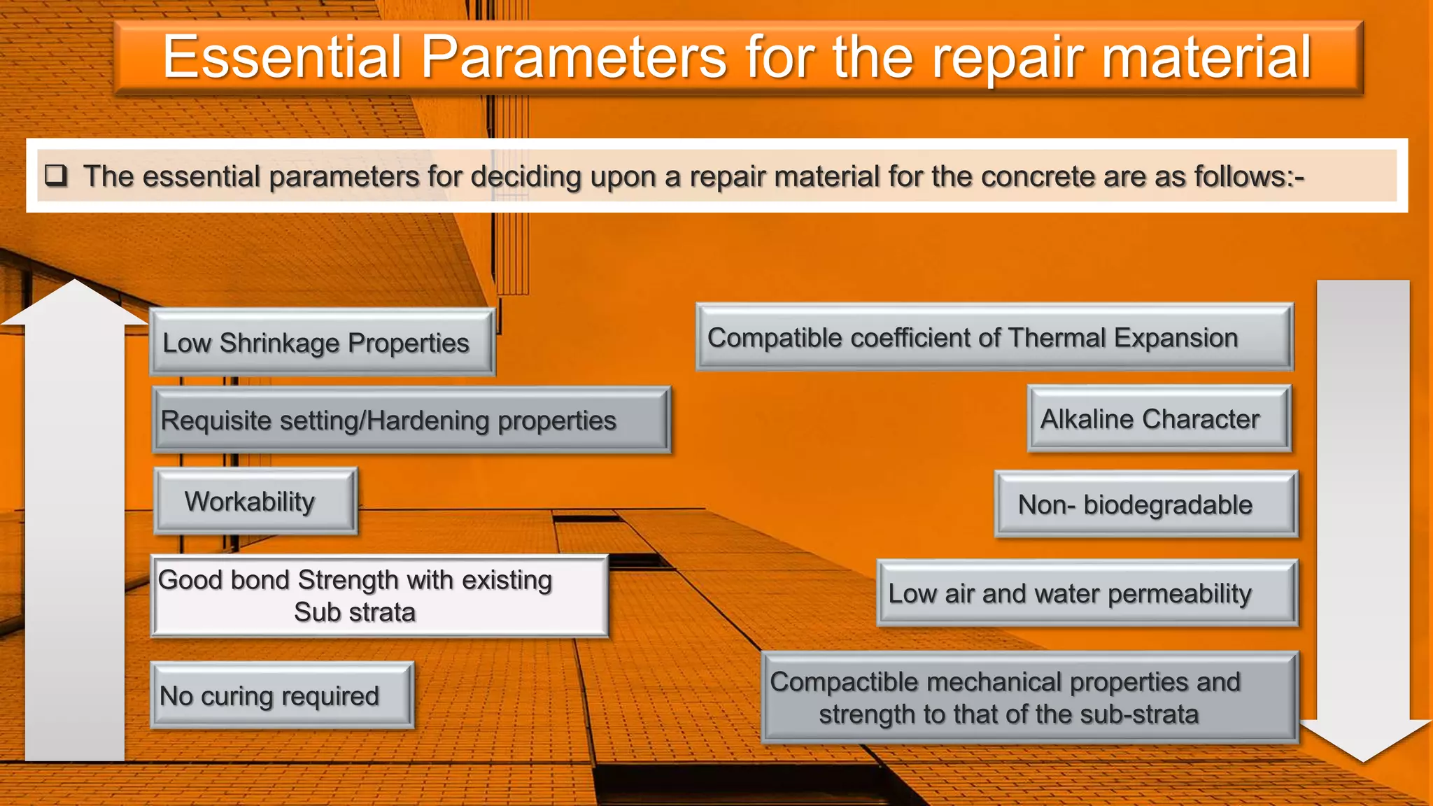
Essential Parameters forthe repair material
The essential parameters for deciding upon a repair material for the concrete are as follows:-
Low Shrinkage Properties
Requisite setting/Hardening properties
Workability
Good bond Strength with existing
Sub strata
Compatible coefficient of Thermal Expansion
Compactible mechanical properties and
strength to that of the sub-strata
No curing required
Alkaline Character
Low air and water permeability
Non- biodegradable
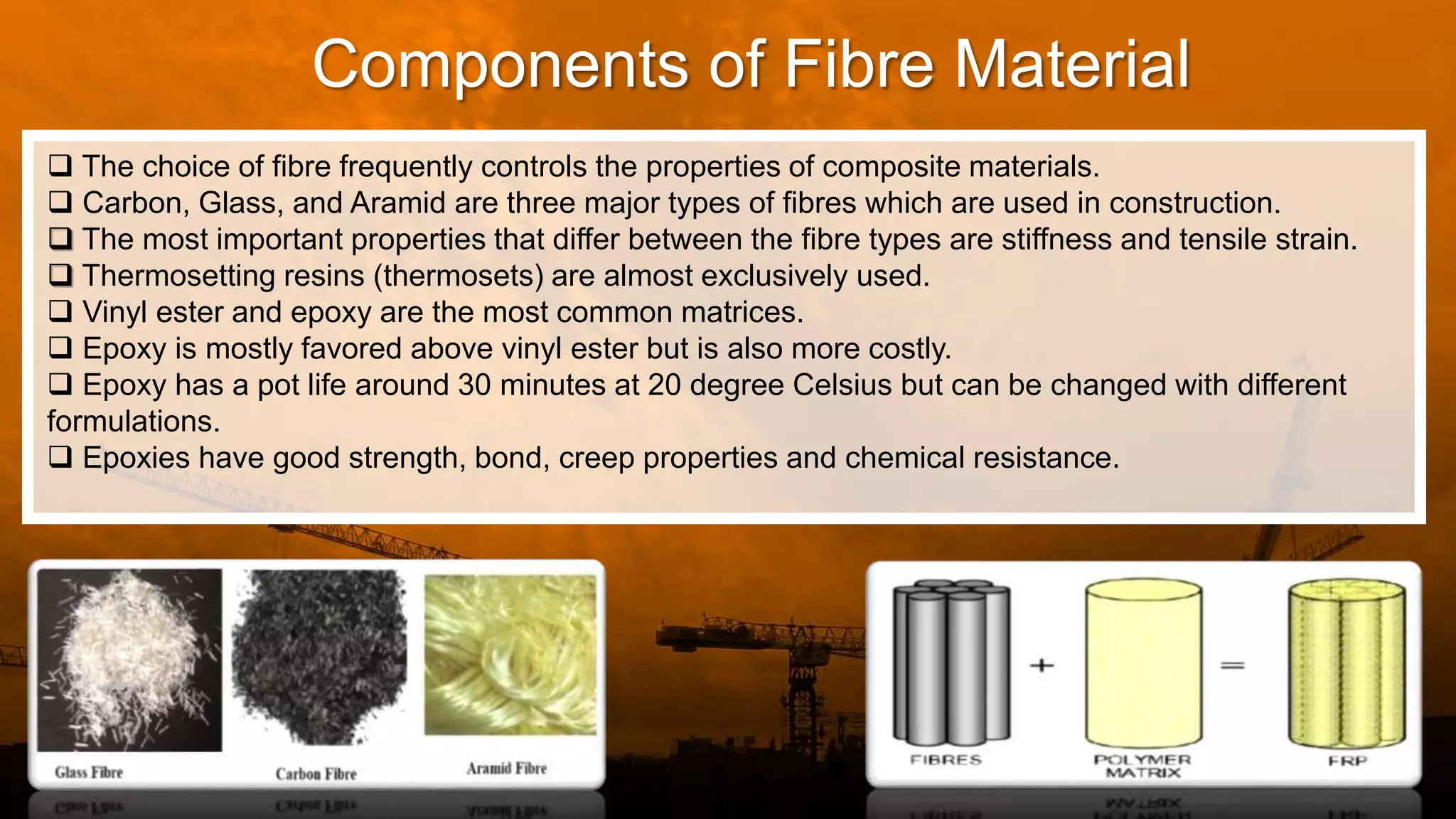
Components of FibreMaterial
The choice of fibre frequently controls the properties of composite materials.
Carbon, Glass, and Aramid are three major types of fibres which are used in construction.
The most important properties that differ between the fibre types are stiffness and tensile strain.
Thermosetting resins (thermosets) are almost exclusively used.
Vinyl ester and epoxy are the most common matrices.
Epoxy is mostly favored above vinyl ester but is also more costly.
Epoxy has a pot life around 30 minutes at 20 degree Celsius but can be changed with different
formulations.
Epoxies have good strength, bond, creep properties and chemical resistance.
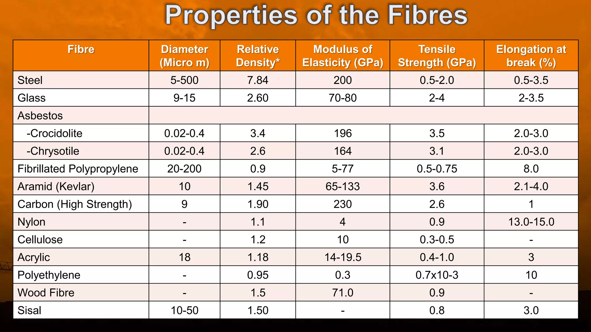
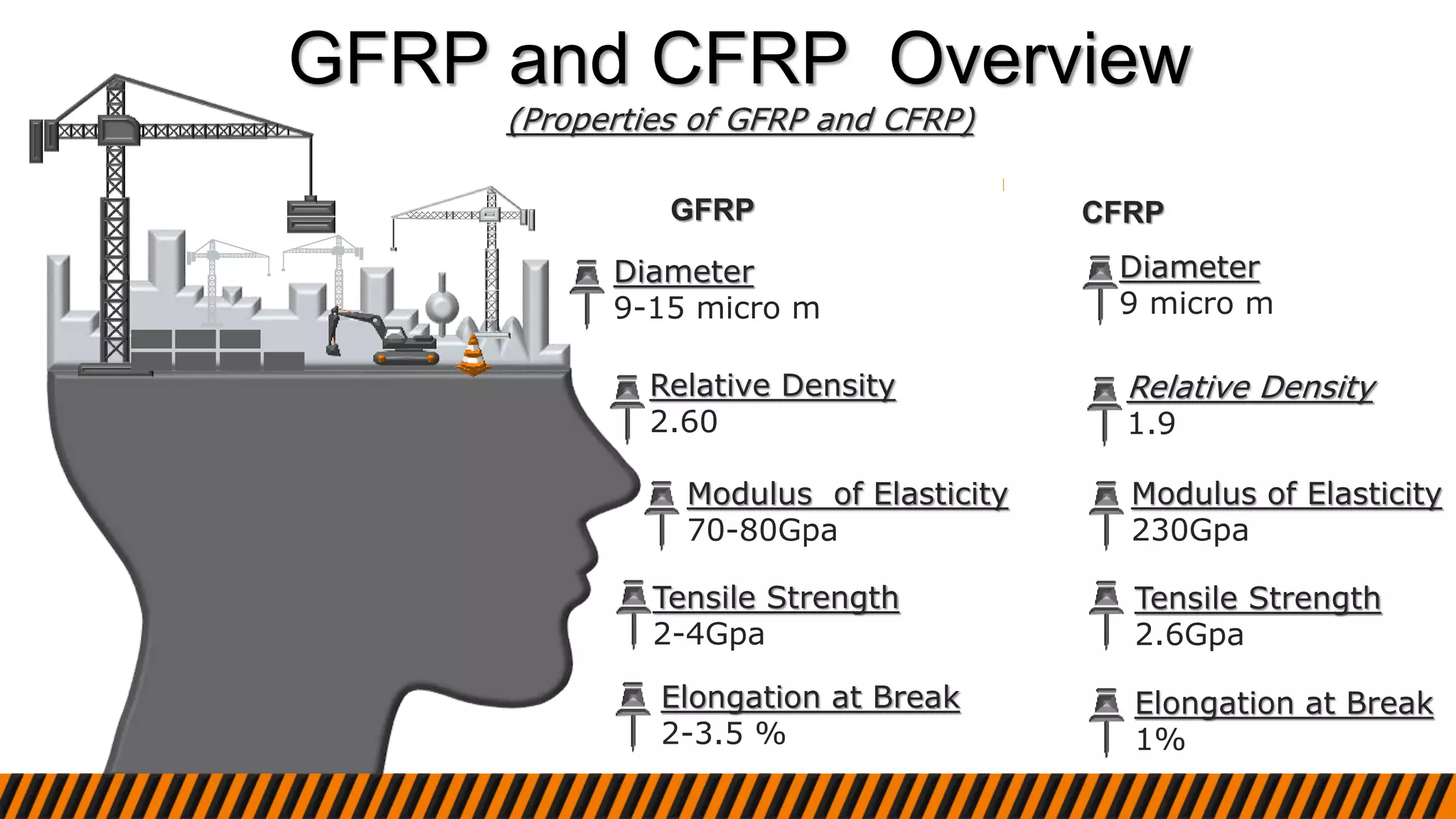
GFRP and CFRPOverview
(Properties of GFRP and CFRP)
Diameter
9-15 micro m
Modulus of Elasticity
70-80Gpa
Relative Density
2.60
Tensile Strength
2-4Gpa
Elongation at Break
2-3.5 %
Diameter
9 micro m
Modulus of Elasticity
230Gpa
Relative Density
1.9
Tensile Strength
2.6Gpa
Elongation at Break
1%
GFRP CFRP
14.
CFRP and GFRPSheet Rates
CFRP
1m X 0.8m
Rate :- Rs900 per runnig m
GFRP
Rate :- Rs350 per kg
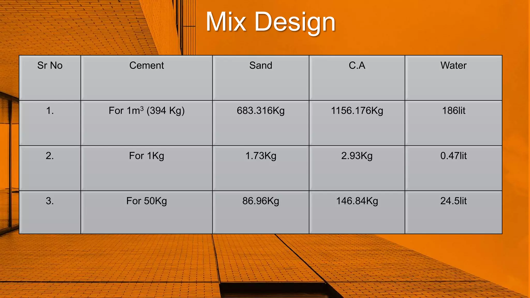
Sr No CementSand C.A Water
1. For 1m3 (394 Kg) 683.316Kg 1156.176Kg 186lit
2. For 1Kg 1.73Kg 2.93Kg 0.47lit
3. For 50Kg 86.96Kg 146.84Kg 24.5lit
Mix Design
31.
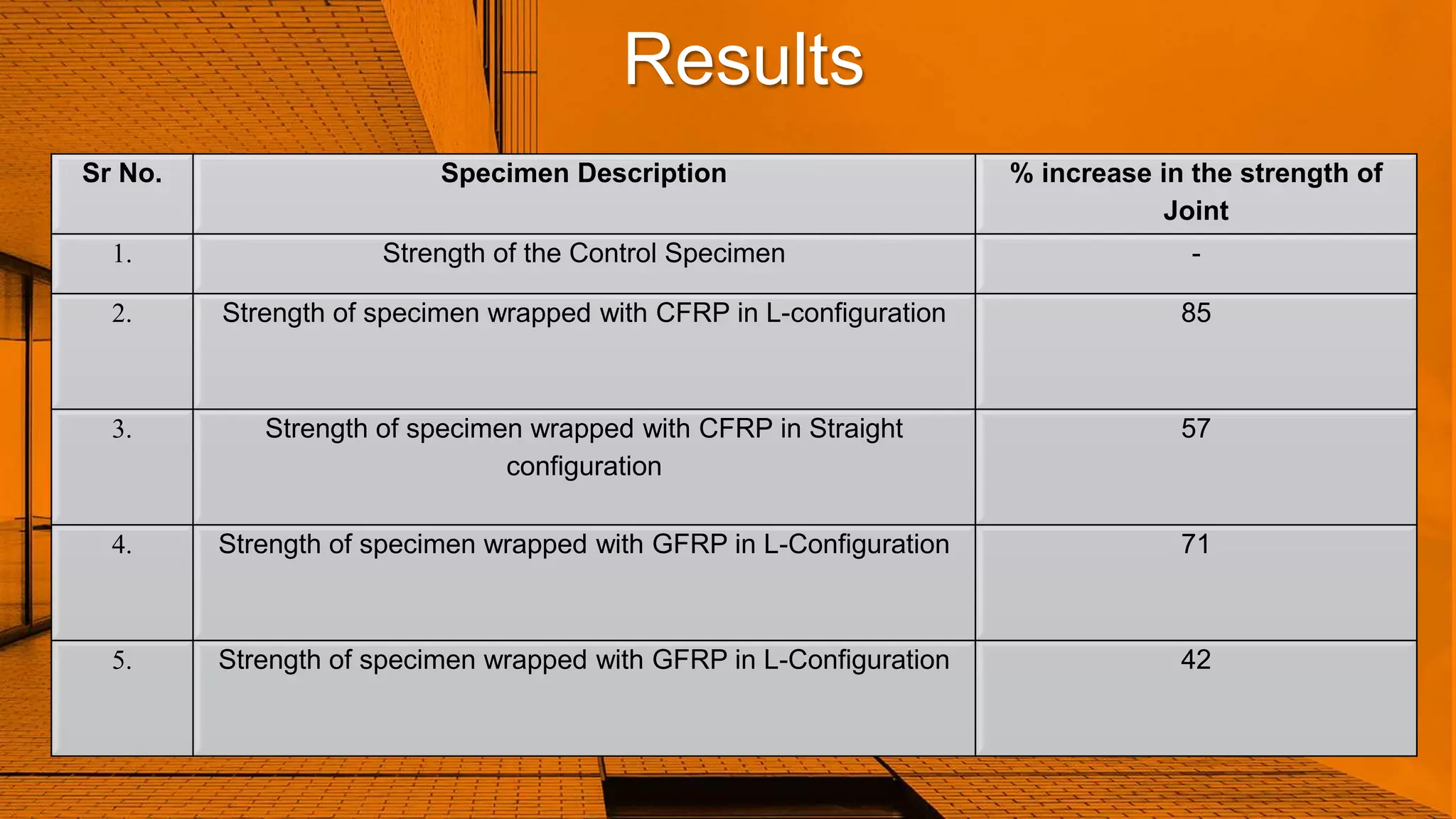
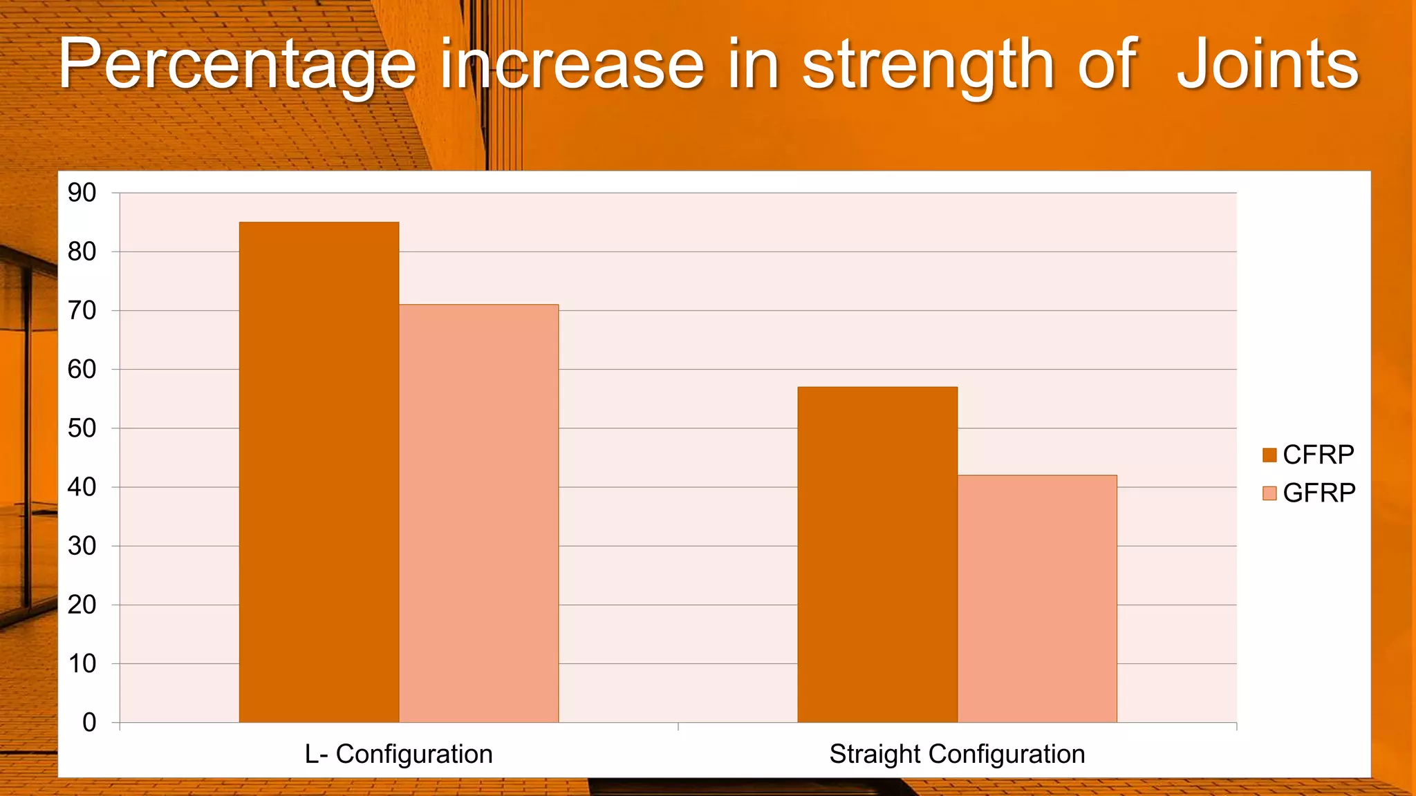
Results
Sr No. SpecimenDescription % increase in the strength of
Joint
1. Strength of the Control Specimen -
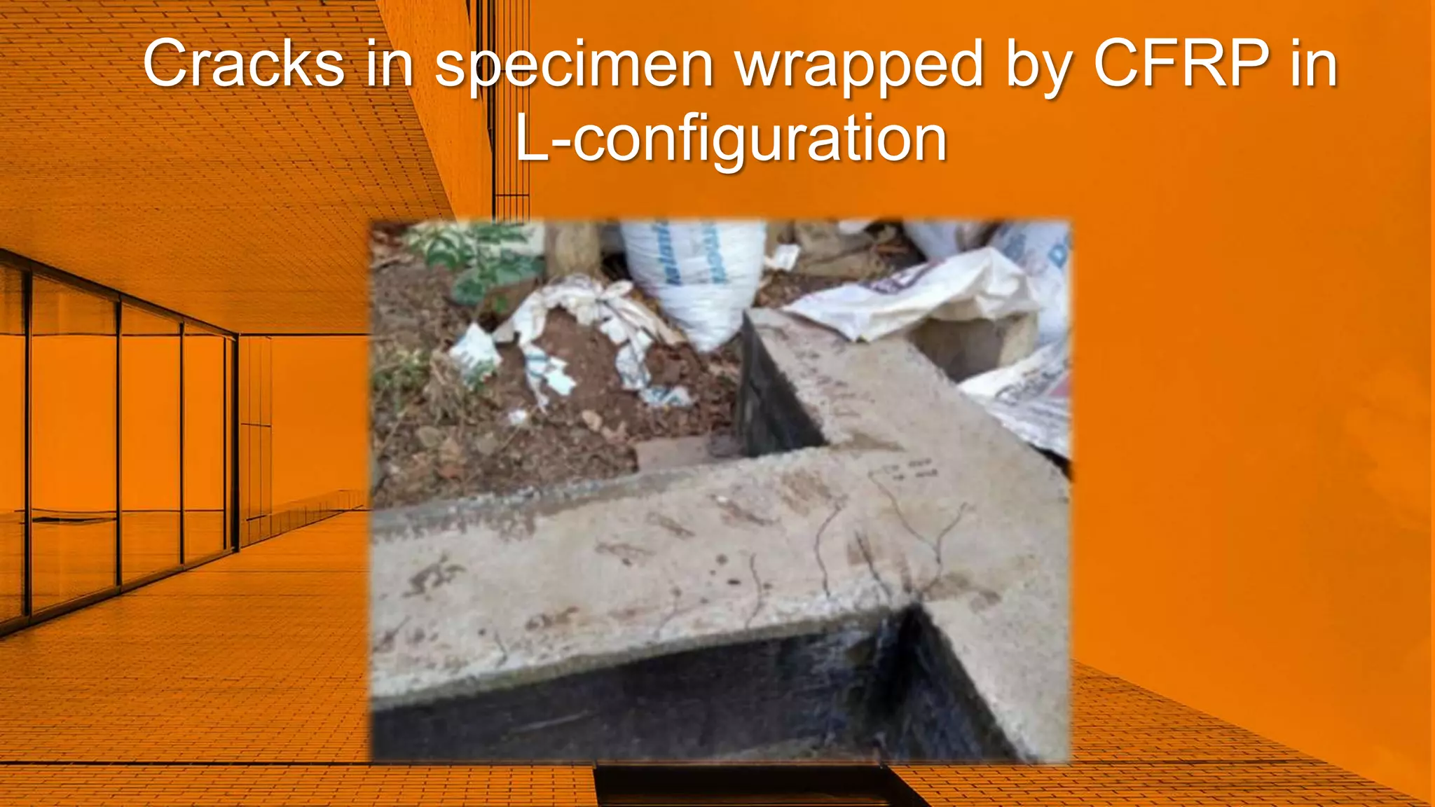
2. Strength of specimen wrapped with CFRP in L-configuration 85
3. Strength of specimen wrapped with CFRP in Straight
configuration
57
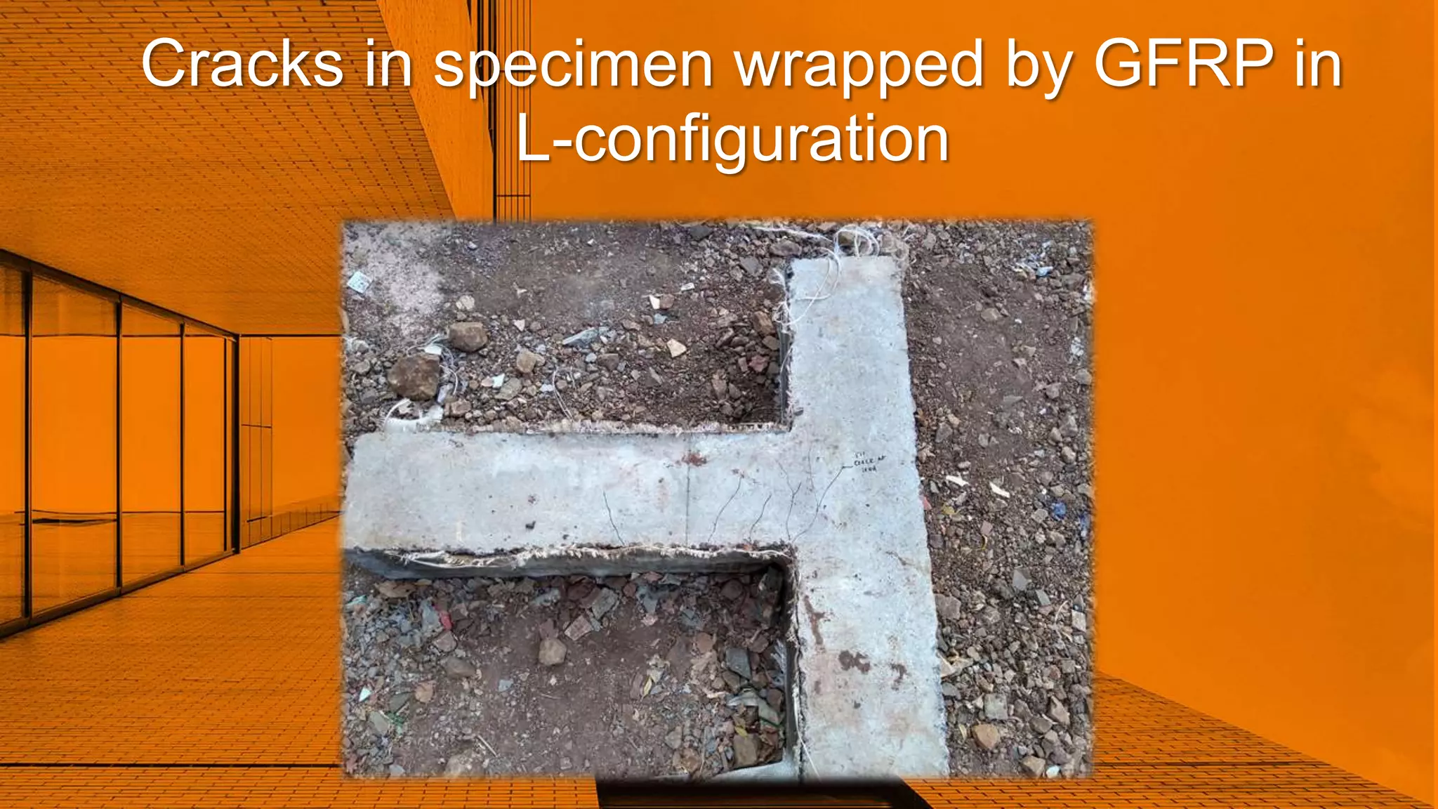
4. Strength of specimen wrapped with GFRP in L-Configuration 71
5. Strength of specimen wrapped with GFRP in L-Configuration 42
32.
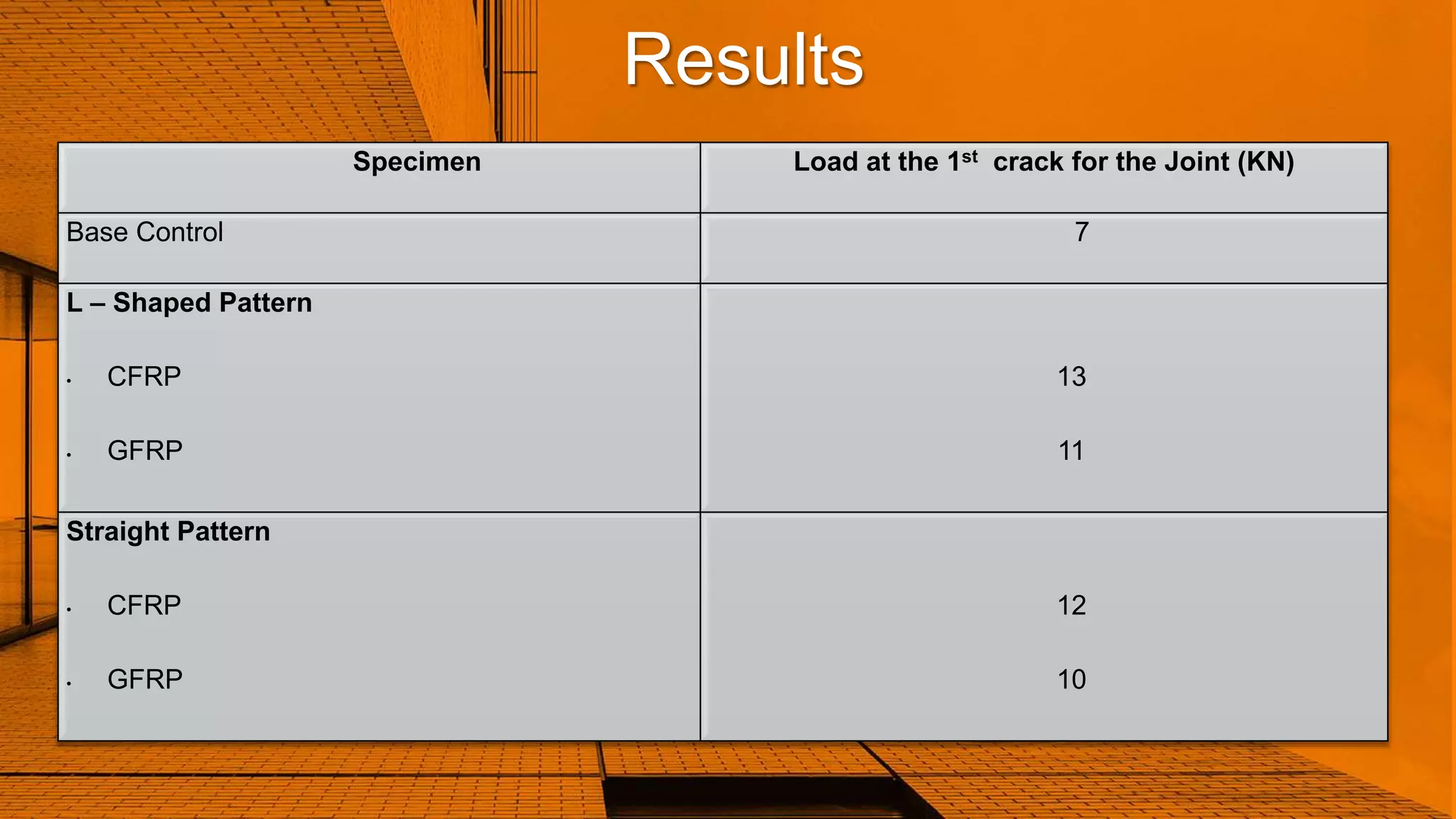
Results
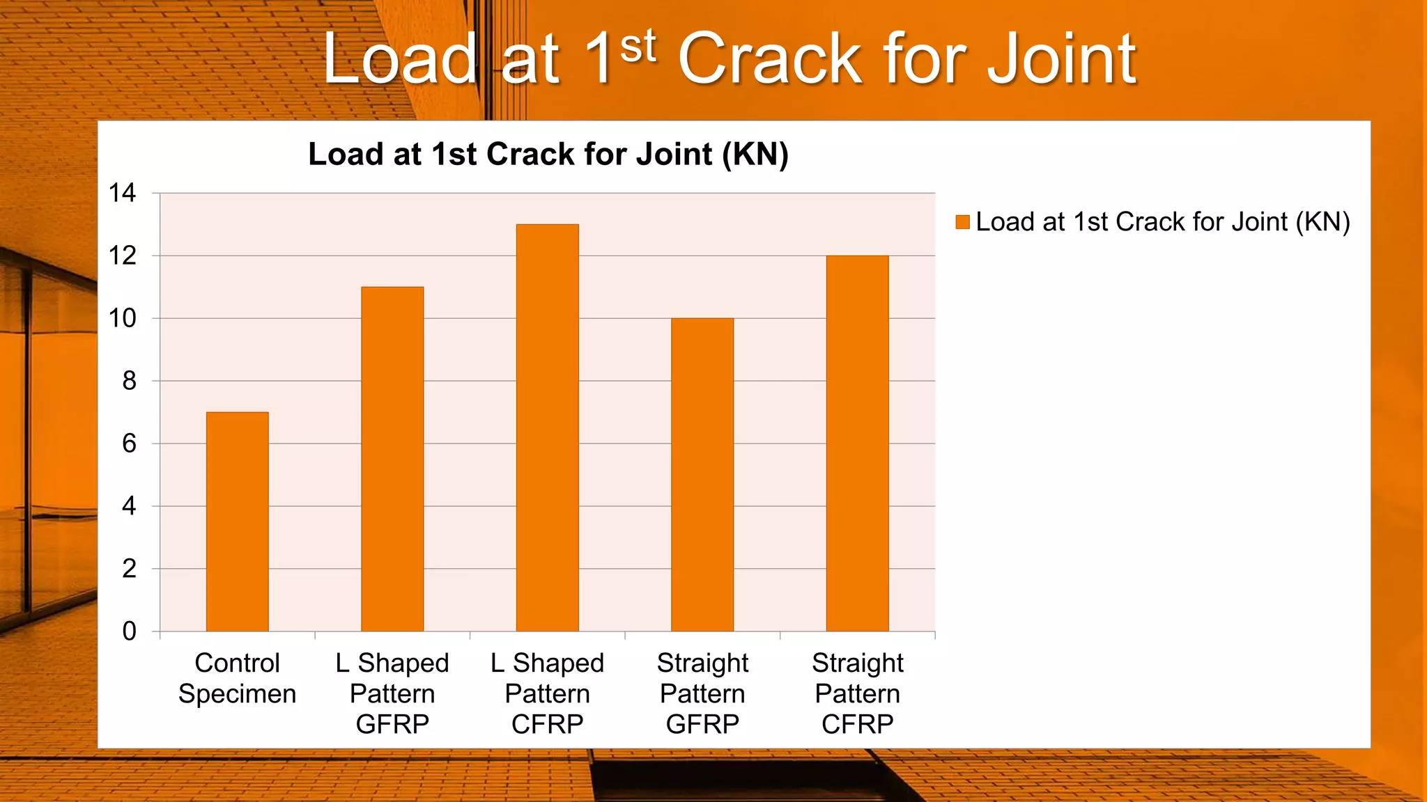
Specimen Load atthe 1st crack for the Joint (KN)
Base Control 7
L – Shaped Pattern
• CFRP
• GFRP
13
11
Straight Pattern
• CFRP
• GFRP
12
10
33.
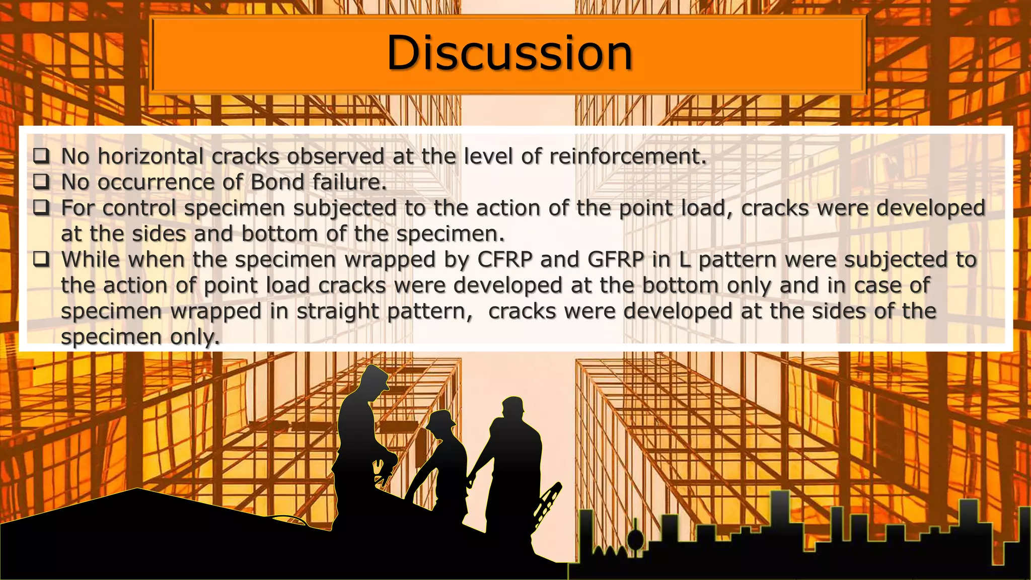
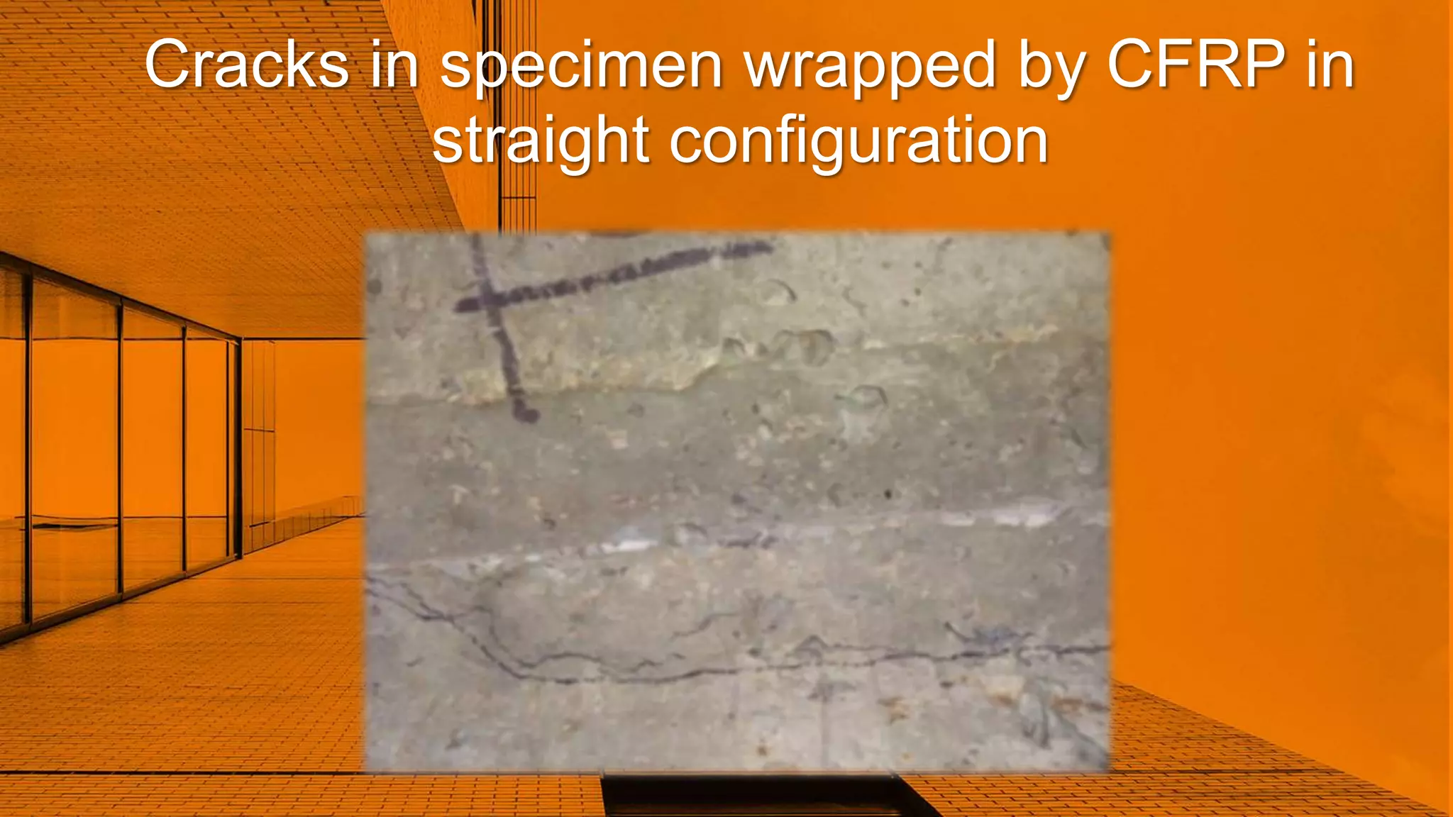
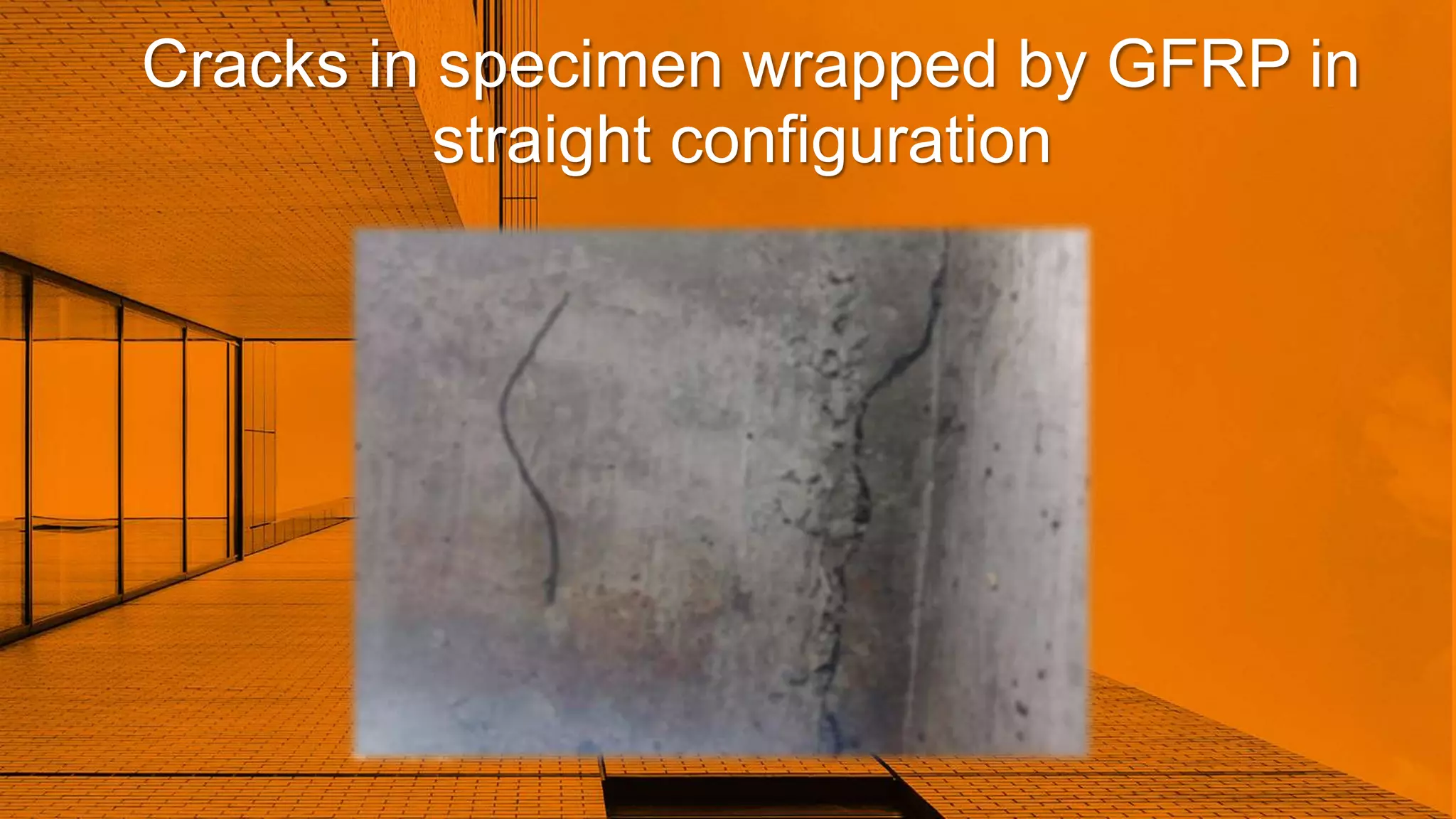
No horizontalcracks observed at the level of reinforcement.
No occurrence of Bond failure.
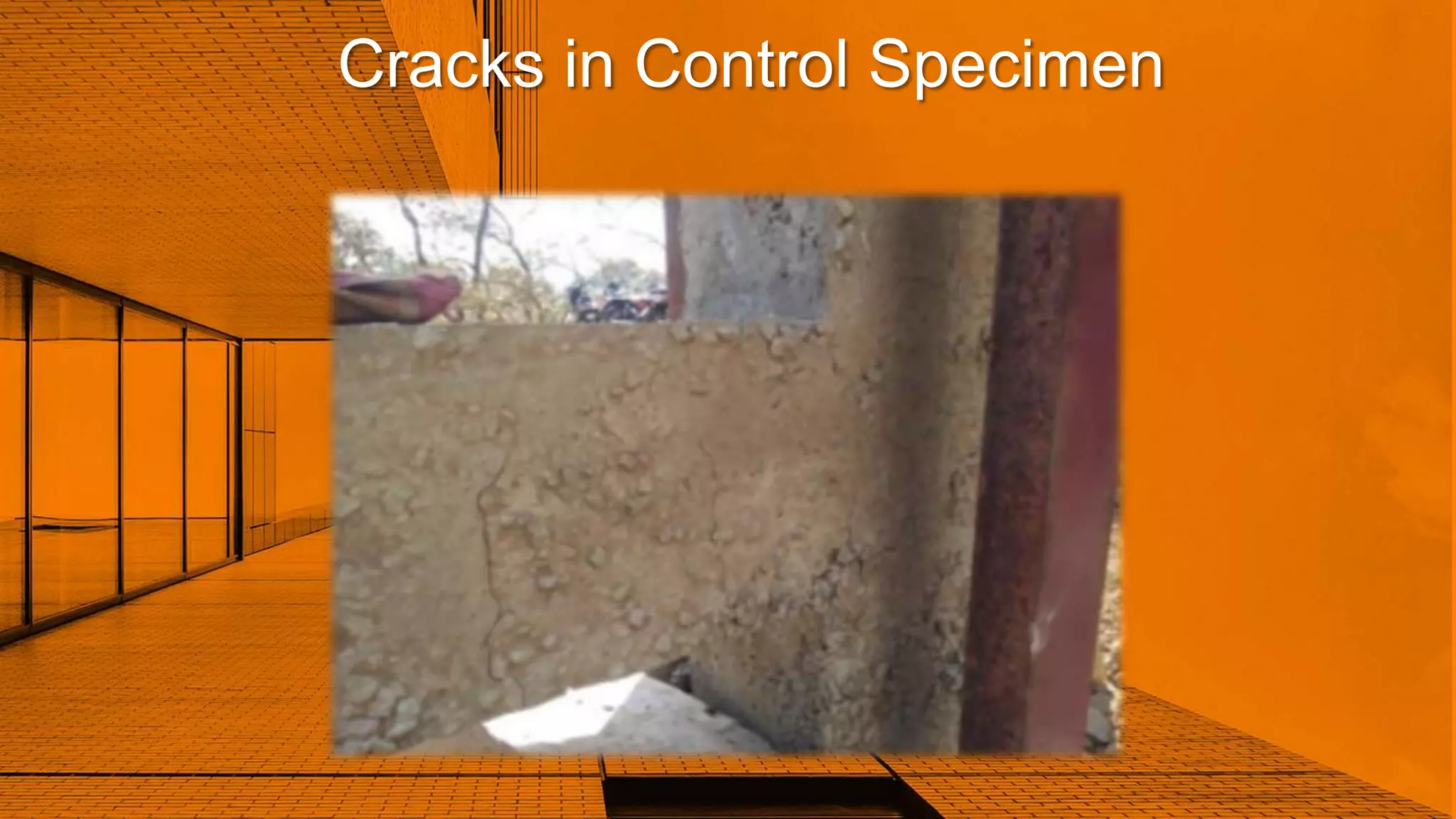
For control specimen subjected to the action of the point load, cracks were developed
at the sides and bottom of the specimen.
While when the specimen wrapped by CFRP and GFRP in L pattern were subjected to
the action of point load cracks were developed at the bottom only and in case of
specimen wrapped in straight pattern, cracks were developed at the sides of the
specimen only.
.
Discussion
34.
Load at 1stCrack for Joint
0
2
4
6
8
10
12
14
Control
Specimen
L Shaped
Pattern
GFRP
L Shaped
Pattern
CFRP
Straight
Pattern
GFRP
Straight
Pattern
CFRP
Load at 1st Crack for Joint (KN)
Load at 1st Crack for Joint (KN)
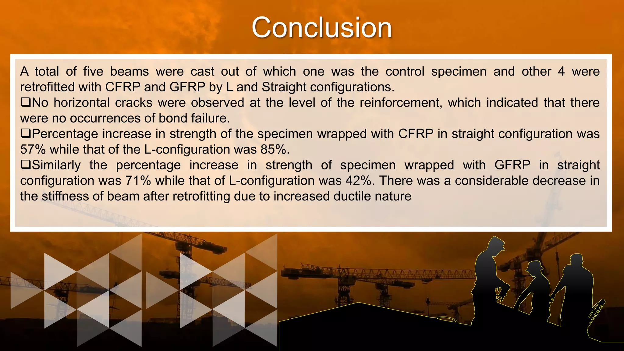
Conclusion
A total offive beams were cast out of which one was the control specimen and other 4 were
retrofitted with CFRP and GFRP by L and Straight configurations.
No horizontal cracks were observed at the level of the reinforcement, which indicated that there
were no occurrences of bond failure.
Percentage increase in strength of the specimen wrapped with CFRP in straight configuration was
57% while that of the L-configuration was 85%.
Similarly the percentage increase in strength of specimen wrapped with GFRP in straight
configuration was 71% while that of L-configuration was 42%. There was a considerable decrease in
the stiffness of beam after retrofitting due to increased ductile nature
42.
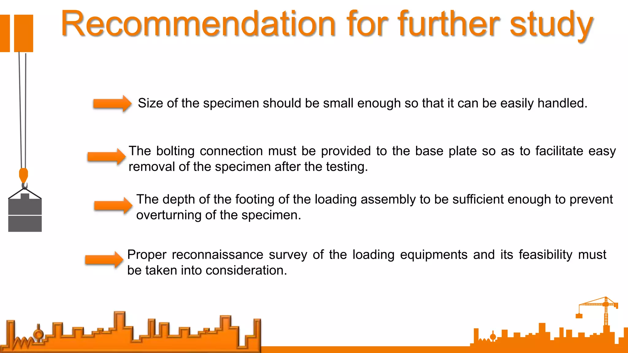
Recommendation for furtherstudy
Size of the specimen should be small enough so that it can be easily handled.
The bolting connection must be provided to the base plate so as to facilitate easy
removal of the specimen after the testing.
The depth of the footing of the loading assembly to be sufficient enough to prevent
overturning of the specimen.
Proper reconnaissance survey of the loading equipments and its feasibility must
be taken into consideration.
43.
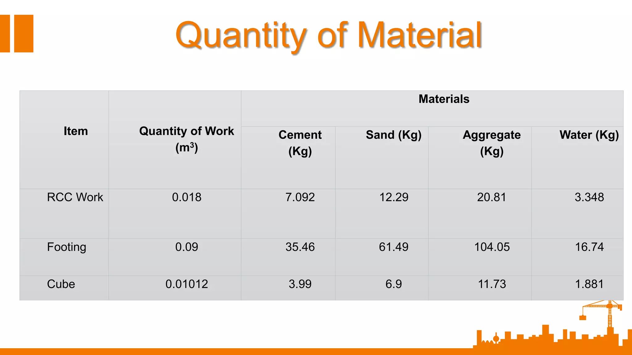
Item Quantity ofWork
(m3)
Materials
Cement
(Kg)
Sand (Kg) Aggregate
(Kg)
Water (Kg)
RCC Work 0.018 7.092 12.29 20.81 3.348
Footing 0.09 35.46 61.49 104.05 16.74
Cube 0.01012 3.99 6.9 11.73 1.881
Quantity of Material
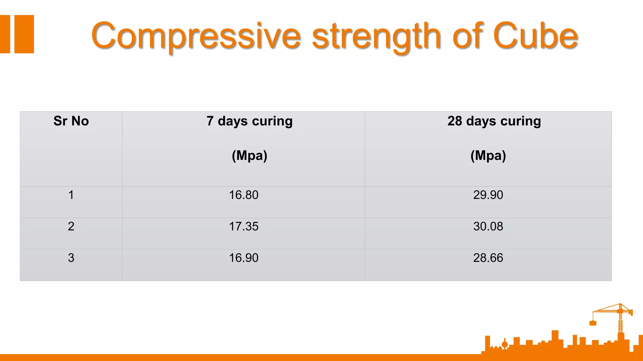
44.
Sr No 7days curing
(Mpa)
28 days curing
(Mpa)
1 16.80 29.90
2 17.35 30.08
3 16.90 28.66
Compressive strength of Cube